


|
|
PIC16F877A-I/PMICROCHIP TECHNOLOGY
|
x 1 | |
|
|
L7805 |
x 1 | |

|
PS1440P02BTTDK Corporation
|
x 1 |

|
Proteus 8 |
|

|
CCS C CompilerCCS
|
PIC16F877A Trainer Board
Build Your Microcomputer || Home-Made Microcontroller Master Trainer Tutorial Bangla

https://www.pcbway.com/?from=technology4power
Every electronic device needs PCBs. Are you looking for the Best PCB order? PCBWay is one the best PCB manufacturing companies. Order 10 pcs PCB for only $5. Visit now https://www.pcbway.com/?from=technology4power
In today's technologically driven world, the ability to create custom electronics projects has become increasingly accessible. One fascinating endeavor in this realm is building your own microcomputer using a PIC16F877A microcontroller. While it might sound daunting at first, with the right guidance and resources, it's a rewarding journey that offers valuable insights into the world of embedded systems and microcontroller programming.
Why microcontroller called a microcomputer?
A microcontroller earns its moniker as a "microcomputer" due to its miniature yet potent computing capabilities. Equipped with a CPU, memory, and versatile input/output ports, microcontrollers resemble traditional computers on a smaller scale. They boast programmability, allowing developers to code in languages like C or assembly to fulfill specific tasks. Often integrated onto a single chip, microcontrollers serve as self-contained computing units, particularly prominent in embedded systems where they efficiently manage dedicated functions. While diminutive in size, microcontrollers pack a punch in functionality, earning them the designation of microcomputers.
Understanding the PIC16F877A Microcontroller
The PIC16F877A microcontroller, manufactured by Microchip Technology, is a versatile and widely used component in electronics projects. It features a robust architecture with ample memory, multiple I/O ports, and various built-in peripherals, making it ideal for a range of applications.
Circuit Design and Prototyping
In the schematic, I will show the complete Microcontroller Master Trainer Diagram. Multiple sections are included in this diagram. Power Supply Unit, Microcontroller Biasing, 8 LED for Binary Data check, 7-segment Display Interfacing, LCD Display Interfacing, Push Button for Input Data Check, Voltage Divider section, etc.
Design the circuit for your microcomputer project, taking into account the connections required by the PIC16F877A microcontroller and any additional components. Utilize a breadboard for prototyping, allowing you to test and iterate on your circuit design before finalizing it.

https://www.pcbway.com/?from=technology4power
Every electronic device needs PCBs. Are you looking for the Best PCB order? PCBWay is one the best PCB manufacturing companies. Order 10 pcs PCB for only $5. Visit now https://www.pcbway.com/?from=technology4power
Here is the PCB Design Section:
This is the PCB Design Section. I am using a Double-layer PCB board which is ordered from PCBWay.

Here I am showing the 3D Design section.
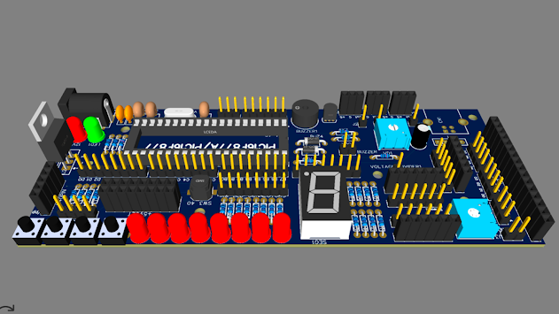
After Completing the Hardware section we need to program for PIC16F877A Microcontroller IC. I am just sharing a sample program for testing your Microcomputer.
Testing and Debugging
Testing and debugging are integral parts of the development process. Use the debugging features provided by your IDE and programmer to step through your code, inspect variables, and identify any issues. Additionally, verify the functionality of your circuit by testing different scenarios and inputs.

I am using the CCSC Compiler to compile my code.
With the development environment set up, it's time to start writing code for your microcomputer project. Begin with simple programs to blink LEDs or read input from switches to familiarize yourself with the PIC16F877A's capabilities. As you gain confidence, you can explore more complex functionalities, such as interfacing with external sensors or driving displays.
Code:
#include<16F877A.h>
#use delay (clock=20MHz)
#FUSES HS
void main()
{
while(true)
{
output_d(0x3F);
delay_ms(1000);
output_d(0x06);
delay_ms(1000);
output_d(0x5B);
delay_ms(1000);
output_d(0x4F);
delay_ms(1000);
output_d(0x66);
delay_ms(1000);
output_d(0x6D);
delay_ms(1000);
output_d(0x7D);
delay_ms(1000);
output_d(0x07);
delay_ms(1000);
output_d(0x7F);
delay_ms(1000);
output_d(0x6F);
delay_ms(1000);
output_b(0x3F);
delay_ms(1000);
output_b(0x06);
delay_ms(1000);
output_b(0x5B);
delay_ms(1000);
output_b(0x4F);
delay_ms(1000);
output_b(0x66);
delay_ms(1000);
output_b(0x6D);
delay_ms(1000);
output_b(0x7D);
delay_ms(1000);
output_b(0x07);
delay_ms(1000);
output_b(0x7F);
delay_ms(1000);
output_b(0x6F);
delay_ms(1000);
}
}
https://www.pcbway.com/?from=technology4power
Every electronic device needs PCBs. Are you looking for the Best PCB order? PCBWay is one the best PCB manufacturing companies. Order 10 pcs PCB for only $5. Visit now https://www.pcbway.com/?from=technology4power
Building your microcomputer using a PIC16F877A microcontroller is a fulfilling endeavor that combines creativity, electronics, and programming. Through this journey, you'll gain valuable skills in embedded systems development, microcontroller programming, and circuit design. Whether you're a hobbyist, student, or professional, the experience of creating your microcomputer opens doors to endless possibilities in the world of electronics and computing. So, roll up your sleeves, gather your components, and embark on this exciting adventure today!
#include<16F877A.h>
#use delay (clock=20MHz)
#FUSES HS
void main()
{
while(true)
{
output_d(0x3F);
delay_ms(1000);
output_d(0x06);
delay_ms(1000);
output_d(0x5B);
delay_ms(1000);
output_d(0x4F);
delay_ms(1000);
output_d(0x66);
delay_ms(1000);
output_d(0x6D);
delay_ms(1000);
output_d(0x7D);
delay_ms(1000);
output_d(0x07);
delay_ms(1000);
output_d(0x7F);
delay_ms(1000);
output_d(0x6F);
delay_ms(1000);
output_b(0x3F);
delay_ms(1000);
output_b(0x06);
delay_ms(1000);
output_b(0x5B);
delay_ms(1000);
output_b(0x4F);
delay_ms(1000);
output_b(0x66);
delay_ms(1000);
output_b(0x6D);
delay_ms(1000);
output_b(0x7D);
delay_ms(1000);
output_b(0x07);
delay_ms(1000);
output_b(0x7F);
delay_ms(1000);
output_b(0x6F);
delay_ms(1000);
}
}
PIC16F877A Trainer Board
Project images are for reference only. Actual production is based on the manufacturing files on the project page.
Please review the designer's notes (e.g., PCB thickness) and select the appropriate options.
PCBWay is not responsible
for issues caused by unsuitable parameter selections.
For more important ordering information, please refer to
Read More


Raspberry Pi 5 7 Inch Touch Screen IPS 1024x600 HD LCD HDMI-compatible Display for RPI 4B 3B+ OPI 5 AIDA64 PC Secondary Screen(Without Speaker)
BUY NOW


- Comments(0)
- Likes(0)
 More by Estiak Khan
-
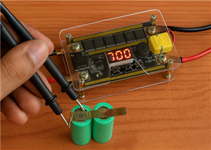 ⚡ How to Make a DIY Spot Welding Machine at Home for 18650 Batteries | Full Circuit & Working
If you’re working on battery pack projects using 18650 lithium-ion cells, then you know how importan...
⚡ How to Make a DIY Spot Welding Machine at Home for 18650 Batteries | Full Circuit & Working
If you’re working on battery pack projects using 18650 lithium-ion cells, then you know how importan...
-
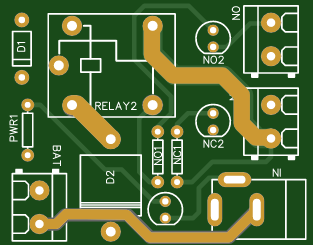
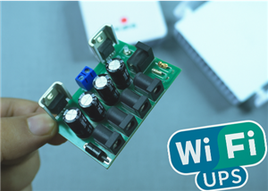 🔋 How to Make a Simple DIY Wi-Fi Router UPS at Home | Step-by-Step Guide with Circuit & PCB
Do you lose internet connection every time the power goes out?If yes, then this simple DIY Wi-Fi Rou...
🔋 How to Make a Simple DIY Wi-Fi Router UPS at Home | Step-by-Step Guide with Circuit & PCB
Do you lose internet connection every time the power goes out?If yes, then this simple DIY Wi-Fi Rou...
-
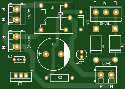 Automatic AC Changeover for Inverter
 – DIY Circuit GuideAre you tired of manually switching between ...
Automatic AC Changeover for Inverter
Automatic AC Changeover for Inverter – DIY Circuit GuideAre you tired of manually switching between ...
-
 How to Make a 12V AC/DC Fan Controller Module
If you're looking for an efficient way to control a 12V fan using either AC or DC input, this DIY pr...
How to Make a 12V AC/DC Fan Controller Module
If you're looking for an efficient way to control a 12V fan using either AC or DC input, this DIY pr...
-
 Autocut DC Mini IPS for DC 12V Load
If you are looking for a reliable Autocut DC Mini IPS for DC 12V ...
Autocut DC Mini IPS for DC 12V Load
Autocut DC Mini IPS for DC 12V LoadIf you are looking for a reliable Autocut DC Mini IPS for DC 12V ...
-
 Build a 12V Battery Autocut System with LCD Display
Are you looking for an efficient and affordable way to protect and monitor your 12V battery system? ...
Build a 12V Battery Autocut System with LCD Display
Are you looking for an efficient and affordable way to protect and monitor your 12V battery system? ...
-
 DIY Transistor Tester | Build Your Own LCR Meter at Home with Arduino Nano
Are you fascinated by electronics and want to create your own tools for testing components? Building...
DIY Transistor Tester | Build Your Own LCR Meter at Home with Arduino Nano
Are you fascinated by electronics and want to create your own tools for testing components? Building...
-
 How to Make a Pure Sine Wave Inverter Using EG8010 + IR2110S | Step-by-Step Guide
If you are looking ...
How to Make a Pure Sine Wave Inverter Using EG8010 + IR2110S | Step-by-Step Guide
How to Make a Pure Sine Wave Inverter Using EG8010 + IR2110S | Step-by-Step GuideIf you are looking ...
-
 🔋 How to Make DC Changeover for Automatic Inverter System | DIY Inverter Changeover Switch
Are you tired of manually switching between DC power supply and battery backup during load shedding?...
🔋 How to Make DC Changeover for Automatic Inverter System | DIY Inverter Changeover Switch
Are you tired of manually switching between DC power supply and battery backup during load shedding?...
-
 No Need Adapter 🤔 WiFi Router UPS Making with Transformer
No Need Adapter WiFi Router UPS Making with Transformer | Complete Circuit DiagramAre you tired of ...
No Need Adapter 🤔 WiFi Router UPS Making with Transformer
No Need Adapter WiFi Router UPS Making with Transformer | Complete Circuit DiagramAre you tired of ...
-
 🔋 How to Make a Power Bank Module at Home
Are you looking to build your own DIY power bank at home? In this blog post, we’ll show you how to c...
🔋 How to Make a Power Bank Module at Home
Are you looking to build your own DIY power bank at home? In this blog post, we’ll show you how to c...
-
 Cute LIT 220W Inverter Load Test ⚡ Auto Changeover IPS System Explained! 🔋 Real Load Backup Test
Are you looking for a reliable backup power solution for your WiFi router, CCTV, or small appliances...
Cute LIT 220W Inverter Load Test ⚡ Auto Changeover IPS System Explained! 🔋 Real Load Backup Test
Are you looking for a reliable backup power solution for your WiFi router, CCTV, or small appliances...
-
 ⚡ Hybrid WiFi Router UPS for Solar System
IntroductionPower cuts in off-grid areas can disrupt internet connectivity. With the rise of solar s...
⚡ Hybrid WiFi Router UPS for Solar System
IntroductionPower cuts in off-grid areas can disrupt internet connectivity. With the rise of solar s...
-
 🔋 DIY Solar-Based Mini IPS at Home | Auto Load Changeover Circuit for 12V DC Fan/Light
If you're looking for an easy and affordable solution to keep your 12V DC fan or light running even ...
🔋 DIY Solar-Based Mini IPS at Home | Auto Load Changeover Circuit for 12V DC Fan/Light
If you're looking for an easy and affordable solution to keep your 12V DC fan or light running even ...
-
 🔋 DIY Automatic Cut Off 12V Trickle Charger | Lead Acid Battery AutoCut Charger
Do you often charge your 12V lead-acid battery manually and worry about overcharging? With this DIY ...
🔋 DIY Automatic Cut Off 12V Trickle Charger | Lead Acid Battery AutoCut Charger
Do you often charge your 12V lead-acid battery manually and worry about overcharging? With this DIY ...
-
 🔥 DIY Smart 12V Battery at Home | Using 18650 Cells + Smart BMS
Looking for a way to build a powerful and smart 12V battery at home? In this guide, I'll show you h...
🔥 DIY Smart 12V Battery at Home | Using 18650 Cells + Smart BMS
Looking for a way to build a powerful and smart 12V battery at home? In this guide, I'll show you h...
-
 🎮 DIY Arduino Nano Snake Game Console with OLED Display
DIY Arduino Nano Snake Game Console with OLED Display and ButtonsDo you love retro games? Want to bu...
🎮 DIY Arduino Nano Snake Game Console with OLED Display
DIY Arduino Nano Snake Game Console with OLED Display and ButtonsDo you love retro games? Want to bu...
-
 DIY 150W IPS Making At Home with Auto Changeover System | Mini IPS 2025
How to Make an Automatic 150W IPS Using Two Circuit ModulesAre you looking for a reliable and effici...
DIY 150W IPS Making At Home with Auto Changeover System | Mini IPS 2025
How to Make an Automatic 150W IPS Using Two Circuit ModulesAre you looking for a reliable and effici...
-
Programmable Mist Maker - XIAO / QT PY Extension
1014 2 1 -
RadioHAT - Raspberry Pi radio development platform
817 0 2 -
-
-
-
-
ARPS-2 – Arduino-Compatible Robot Project Shield for Arduino UNO
3277 0 6 -
A Compact Charging Breakout Board For Waveshare ESP32-C3
3897 3 8 -
AI-driven LoRa & LLM-enabled Kiosk & Food Delivery System
4277 2 2


