


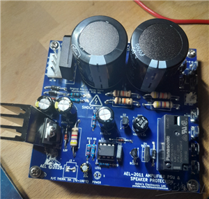
AEL-2011 Power Supply Module
NOTE: THIS INVOLVES MAINS WIRING AND MAINS POTENTIAL. IF YOU ARE NOT CONFIDENT IN HANDLING MAINS WIRING, DO NOT ATTEMPT THIS PROJECT.
Introduction
This power supply module is intended for use with the AEL-2011 power amplifier, described here, but can be used as the basis for any amplifier power supply. This features a DC detection circuit and muting function to prevent speakers from being destroyed if the amplifier connected to them has a DC fault condition.
Construction
Do not install Q1 or the heatsink until everything else is installed first. Construction is straight forward as all components mount on a single PCB. Begin construction by installing all of the 1/2W metal film resistors taking note of R4. R4 is marked on the schematic as 150k, but marked as 330k on the PCB silkscreen. 150k is the correct value to install here and was changed as the on-delay for the relay was too long (over 12 seconds).
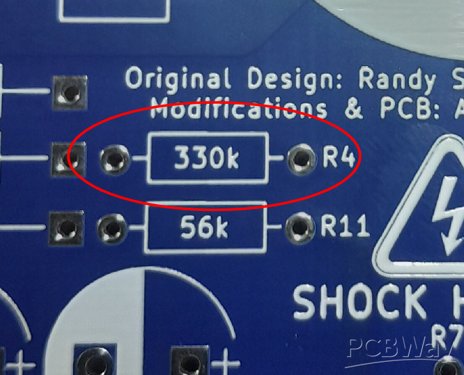
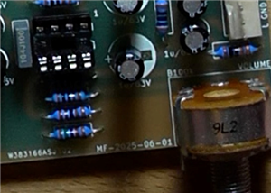
Figure 1: The red ellipse shows the resistor value as 330k on the PCB silkscreen. This needs to be changed to 150k.
All diodes D1 to D5. If you wish to use an 8-pin DIL IC socket for U1, this can be installed next (I would recommend doing this, as it's much easier to change the IC if socketed). ZD1 and the 1W resistors can be installed next giving each device an "air-gap" away from the PCB. This ensures good air flow around the component and prevents the PCB from being charred as the device heats up.
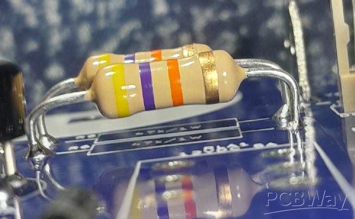
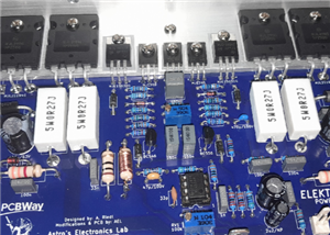
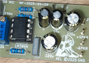
Figure 2: Example "air-gap" of the 1W resistors. This helps with air flow around the component and prevent charring of the PCB if they get hot. ZD1 should also have an "air-gap".
Next, install the nine 6.3mm male spade terminals. I bought mine from Jaycar and they have a 5mm pin pitch with 1mm diameter pins. You can get similar ones from Digikey or Altronics, however the pin diameter maybe larger (up to 1.4mm). This is easy to get around by taking a small file to the pins and taking of enough material for them to fit through the PCB holes. The Jaycar ones are all ready a snug fit as the hole diameters in the PCB are 1.1mm, so it may be tight! J1 can also be installed (this is optional to install if you want to have access to the main supply rails later for another PCB, such as a preamplifier with it's own regulators).
J1 can be installed next along with J3 (the temperature switch) if you choose to use is, with one caveat. If you don't wish to use a temperature switch, J3 can be negated; however, a link wire will have to be installed across J3 or the circuit will not allow the relay to ever engage.
[J3]

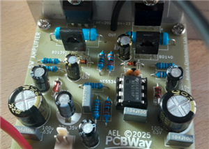
Figure 3: Take not if not using an external temperature switch, then J3 needs to be "shorted" with a link wire. Failure to do so will result in non-operation of the relay.
LED1 is both the power indicator and the mute/fault flashing indicator and should be on the front panel. You can install a male header similar similar to J2 to acheive this. If you didn't use an IC socket for U1, then you can solder this in now the correct way around. Pin 1 points to the heatsink.
C7 can be installed now along with DB2, Q2 and Q3. Q4 can be installed next followed by all the electrolytic capactitors noting polarity (C4 is non-polarised and can go either way around). Relay RLA1 can be installed followed by DB1, noting the notch of the device is positive and faces the top of the PCB and finally C1 and C2. Now, you can turn your attention to Q1 and the heatsink. You don't have to, but I would suggest insulating Q1 from the heatsink using a TO-220 SIL pad and M3 isolator bushing. Using a 6mm long M3 screw, pass the bushing over the screw through the mounting hole of Q1, place the SIL washer on the back of the transistor and line the screw up to the tapped hole in the heatsink.
Loosely tighten the screw so the transistor and SIL washer can move independant of the heatsink. Line the heatsink and the transistor up to the holes provided in the PCB and push the heatsink flat with the top of the board. Checking everything looks straight and you don't have any bent pins on the transistor, solder the heatsink lugs on the underside of the board. Now tighten the transistor to the heatsink; tight enough, you don't need to kill it! Finally, Q1 can be soldered in.
If you used an IC socket for U1, then pop an NE555 timer IC in to the socket the correct way around (pin 1 points to the heatsink). And that completes assembly.
Testing
Connect up a suitable transformer to J1, a 25-0-25V toroidal (around 300VA) will give us roughly the +/-35V supply rails. You can use a 30-0-30V (300VA) and that will give us +/-42V supply rails, but I would not exceed this. I would suggest using a "dim-blub" (an incandescent/hallogen 40W, or so, light bulb) in series with the live AC input of the transformer to help limit the current if there is a fault with construction or components. It's not necessary, but helpful. If you don't have a dim-bulb, then you must install a series line fuse of the recommended value of the manufacturer with the live wire. If there's a short, the fuse blows, simple.
Make sure LED1 is connected to circuit and apply power. It should begin to flash at around 1.5Hz and after about 4 - 5 seconds, you should hear a mechanical click from RLA1. The LED should now appear to be solid (no longer flashing). If the dim-bulb is glowing brightly (or the fuse blows), there's a definate fault such as a short. Check and correct the problem. Assuming that the circuit appears to be functioning, check each voltage rail with respect to GND (Vcc & Vee) are close to +/-35V (+/-42V on the maximum allowed secondary voltage), which they should be +/-2V, or so. Next, carefully connect a clip lead wire to Vcc and carefully touch it to either R-IN or L-IN. The relay should drop out and LED1 begins flashing; and as long as the clip lead isn't touching either terminal, the relay should then re-engage after 4 - 5 seconds and LED1 becomes solid again. Repeat the same test with the clip lead connected to Vee and confirm the operation is the same.
That's it. The module is working.
Link to my YouTube video on this module:
AEL-2011 Power Supply Module
Project images are for reference only. Actual production is based on the manufacturing files on the project page.
Please review the designer's notes (e.g., PCB thickness) and select the appropriate options.
PCBWay is not responsible
for issues caused by unsuitable parameter selections.
For more important ordering information, please refer to
Read More


Raspberry Pi 5 7 Inch Touch Screen IPS 1024x600 HD LCD HDMI-compatible Display for RPI 4B 3B+ OPI 5 AIDA64 PC Secondary Screen(Without Speaker)
BUY NOW


- Comments(0)
- Likes(3)
More by Astro's Electronics Lab
-
 AEL-2011 Power Supply Module
NOTE: THIS INVOLVES MAINS WIRING AND MAINS POTENTIAL. IF YOU ARE NOT CONFIDENT IN HANDLING MAINS WIR...
AEL-2011 Power Supply Module
NOTE: THIS INVOLVES MAINS WIRING AND MAINS POTENTIAL. IF YOU ARE NOT CONFIDENT IN HANDLING MAINS WIR...
-
 AEL-2011 50W Power Amplifier
IntroductionThis little amplifier module measuring 100mm by 100mm is capable of producing 50W into 8...
AEL-2011 50W Power Amplifier
IntroductionThis little amplifier module measuring 100mm by 100mm is capable of producing 50W into 8...
-
 Elektor PA300 300W Power Amplifier
NOTE: This is an intermediate project; DO NOT attempt this as your first project if you’re a novice....
Elektor PA300 300W Power Amplifier
NOTE: This is an intermediate project; DO NOT attempt this as your first project if you’re a novice....
-
 Simple 45W Discrete Power Amplifier
This simple amplifier is capable of producing up to 45W in to 8 ohms at the specified supply rails o...
Simple 45W Discrete Power Amplifier
This simple amplifier is capable of producing up to 45W in to 8 ohms at the specified supply rails o...
-
 555 Timer 12VDC Motor Speed Controller
Using a 555 timer and PWM (Pulse-Width Modulation), by varying its duty-cycle, we can vary the speed...
555 Timer 12VDC Motor Speed Controller
Using a 555 timer and PWM (Pulse-Width Modulation), by varying its duty-cycle, we can vary the speed...
-
 Headphone Adaptor for Power Amplifiers
Add a headphone socket to any existing stereo amplifier that doesn't have one. This L-pad attenuator...
Headphone Adaptor for Power Amplifiers
Add a headphone socket to any existing stereo amplifier that doesn't have one. This L-pad attenuator...
-
 Soft-Start Circuit for Toroidal Transformers
WARNING: This project is connected to mains line voltage during its entire operation. This project s...
Soft-Start Circuit for Toroidal Transformers
WARNING: This project is connected to mains line voltage during its entire operation. This project s...
-
 AEL-50B Simple 50W Power Amplifier
Need a simple power amplifier to drive a loudspeaker that doesn't require any messy set-ups to get g...
AEL-50B Simple 50W Power Amplifier
Need a simple power amplifier to drive a loudspeaker that doesn't require any messy set-ups to get g...
-
 150W Lateral MOSFET Power Amplifier
NOTE 1: This project is not intended for beginners. It is intended for someone with a medium underst...
150W Lateral MOSFET Power Amplifier
NOTE 1: This project is not intended for beginners. It is intended for someone with a medium underst...
-
 Elektor Austereo 5W Stereo Amplifier
IntroductionThis little stereo amplifier will happily produce 5W RMS per-channel into 8 ohms and fea...
Elektor Austereo 5W Stereo Amplifier
IntroductionThis little stereo amplifier will happily produce 5W RMS per-channel into 8 ohms and fea...
-
 Simple NE5532 Stereo Preamplifier
Need a simple stereo preamplifier for a set of power amplifiers? Here's the solution. Based on an NE...
Simple NE5532 Stereo Preamplifier
Need a simple stereo preamplifier for a set of power amplifiers? Here's the solution. Based on an NE...
-
 NE5534 5W Utility Power Amplifier PSU
This power supply was intended for the NE5534 power amplifier project:https://www.pcbway.com/project...
NE5534 5W Utility Power Amplifier PSU
This power supply was intended for the NE5534 power amplifier project:https://www.pcbway.com/project...
-
 LM386 Amplifier For Electret Microphone (Bullhorn)
This little circuit was originally designed to have an electret microphone insert connected at the i...
LM386 Amplifier For Electret Microphone (Bullhorn)
This little circuit was originally designed to have an electret microphone insert connected at the i...
-
 NE5534 5W Utility Power Amplifier
I needed a small amplifier to drive a pair of bookshelf speakers for testing other audio gear, such ...
NE5534 5W Utility Power Amplifier
I needed a small amplifier to drive a pair of bookshelf speakers for testing other audio gear, such ...
-
 Guitar Practice Amplifier (0.5W)
This little amplifier will happily drive a 4 - 8 ohm speaker to pretty loud levels, complete with ov...
Guitar Practice Amplifier (0.5W)
This little amplifier will happily drive a 4 - 8 ohm speaker to pretty loud levels, complete with ov...
-
 100mW Utility Amplifier
Need a small amplifier to amplify a radio front-end, or similar? This will do it! It produces up to ...
100mW Utility Amplifier
Need a small amplifier to amplify a radio front-end, or similar? This will do it! It produces up to ...
-
 Car Alarm Deterrent Flasher
We've all seen them; a bright red flashing light on someone's car's dash board to indicate there is ...
Car Alarm Deterrent Flasher
We've all seen them; a bright red flashing light on someone's car's dash board to indicate there is ...
-
 555 Timer Bi-Stable AC Mains Switch
WARNING: THIS CIRCUIT IS CONNECTED DIRECTLY TO THE MAINS SUPPLY AND CAN BE DANGEROUS. EXTREME CARE S...
555 Timer Bi-Stable AC Mains Switch
WARNING: THIS CIRCUIT IS CONNECTED DIRECTLY TO THE MAINS SUPPLY AND CAN BE DANGEROUS. EXTREME CARE S...
-
Programmable Mist Maker - XIAO / QT PY Extension
1130 2 1 -
RadioHAT - Raspberry Pi radio development platform
939 0 2 -
-
-
-
-
ARPS-2 – Arduino-Compatible Robot Project Shield for Arduino UNO
3365 0 6 -
A Compact Charging Breakout Board For Waveshare ESP32-C3
3980 3 8 -
AI-driven LoRa & LLM-enabled Kiosk & Food Delivery System
4369 2 2


