


|
KiCADKicad
|
150W Lateral MOSFET Power Amplifier
NOTE 1: This project is not intended for beginners. It is intended for someone with a medium understanding of electronics and electronic components and soldering skills. Do NOT attempt this as your first project.
NOTE 2: This project involves elevated DC voltages (+/-56VDC or 112VDC rail-to-rail). Do NOT attempt this project if you aren't confident around these voltages and don't know exactly what you are doing.
NOTE 3: Please do not ask PCBWay for assembly of this project, as I will NOT provide any assistance in sourcing the output MOSFETs if they didn't read this article. This is a DIY (Do It Yourself) project. You can, however, ask them to assemble everything else excluding the output stage.
Original publication date: December 13, 2025; Updated Feburary 14, 2026
Introduction
This amplifier, using lateral MOSFETs as the output stage will happily provide 100W into 8 ohms and upto 150W into 4 ohms at +/-56VDC. I haven't tested this above +/-31VDC, however at this stage, but will do in the future and update this project; and managed to produce 35W into 8 ohms and 46W into 4 ohms. So, it isn't really hard to expect or predict the above mentioned powers. It also produces tight bass response as well as clean, crisp highs - what one would expect from a MOSFET power stage!
The output MOSFETs can ONLY be sourced from a UK website called Profusion, and not from anywhere else such as China (they're not available on Mouser or Digikey). If you can source them from China, I'd be very wary of their ability to do the job as they would most likely be counterfeit. Expect to pay a little over $100 AU including shipping from Profusion. The N-Channel can be ordered from here and the P-Channel from here. Note, that at the time of writing this article, the P-Channel is currently unavailable showing 0 stock. However, I have contacted them and the product is still currently active and they expect to have stock by Feburary 2026; there is some form of manufacturing issue leading to it being currently out of stock. Don't ask me, that's just what they told me!
Do NOT use any other MOSFET such as HEXFETs other than what's specified. Aside from the pinouts possibly being different, the circuit is NOT designed to use them and will ultimately blow up and lead to the amplifier self-destructing. A possible substitute, if you have or can find genuine ones (as they're obsolete) are the 2SK1058 for the N-Channel and 2SJ162 for the P-Channel. If you find these from China (AliExpress, etc.), they'll most likely not be genuine and suspiciously cheap. I would avoid buying any semiconductors from AliExpress... actually, anything. The same also applies for semiconductors found on Amazon and eBay; you have no idea where they're coming from.
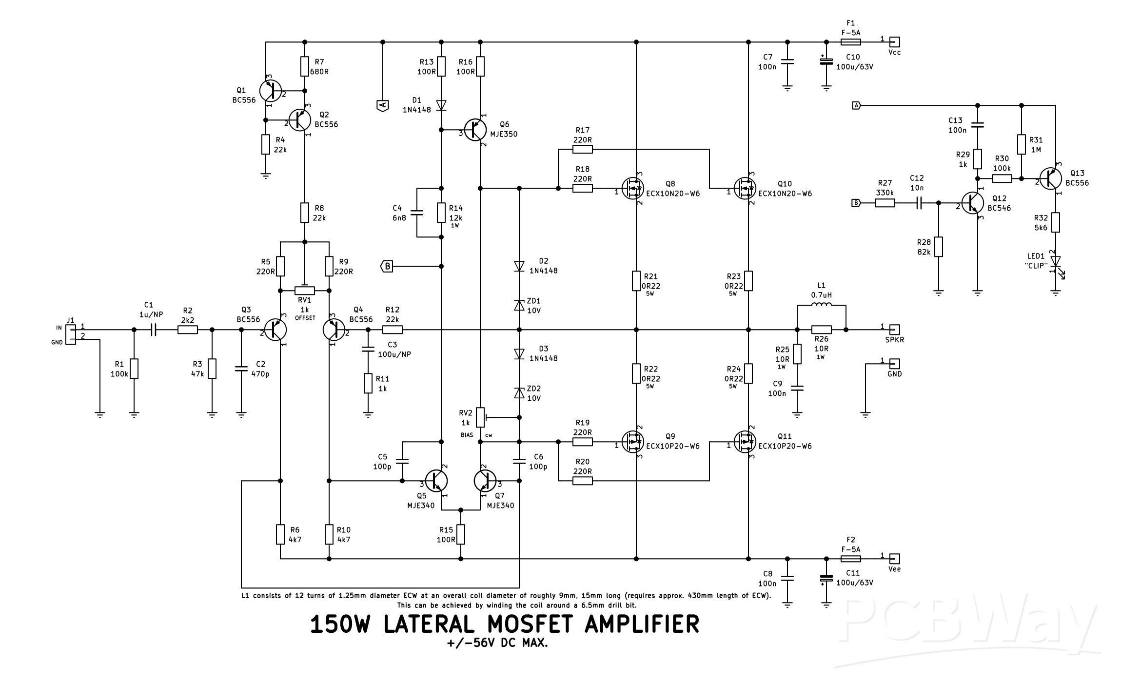
The Circuit
Turning to the circuit, it's a fairly typical design with a LTP (long-tail-pair) input stage (Q3, Q4); a constant current source for the LTP comprising of Q1 and Q2 providing about 1mA. Following the LTP is a differential VAS (voltage amplification stage) consisting of Q5 and Q7 with Q6 being used as a constant current source providing about 5mA to Q7, and about 5mA being sourced via R14 for Q5. The entire VAS consumes around 10mA. RV1 allows trimming of the DC offset that will most likely be present on the output to close to 0V, and RV2 adjusts the overall bias of the output stage. D2, D3 and ZD1 and ZD2 limit the gate voltage of the output MOSFETs to 10V in the event of a fault (such as a short cicuit on the output). I haven't tested shorting the output to see what would happen; however, the fuses most likely would blow and hopefully the MOSFETs would remain undamaged. No amplifier output should ever be shorted, even for testing!
The output stage, consisting of MOSFETs Q8/Q10 and Q9/Q11 is a common-drain source-follower push-pull configuration. This is similar to an emitter-follower bipolar transistor output stage forming a voltage follower; ie: the output stage provides no voltage gain, it just produces the current to drive the load. This also provides a fairly low output impedance (I measured an output impedance as low as 0.122 ohm) and improves the amplifier's damping factor (its ability to dampen speaker cone movement from continuing to oscillate well after the transient is gone - a bit like a shock absorber in a car's suspension).
Q12 and Q13 form a basic "clipping" detector circuit, where point "B" is connected to the collector of Q5 (first half of the VAS) and point "A" to the positive supply rail. As Q5 is connected on the "error" side of the amplifier, that is the negative feedback side which is used to correct errors on the output back to the LTP, the signal developed here can be used to determine output performance regardless of the load impedance or supply voltage. Q12 is basically a common-emitter amplifier which receives this error signal via R27 (an isolation resistor) and AC coupling capacitor C12. Once Q12 is biased on by the positive-going input signal from C12, the increasing collector current quickly charges C13 via R29 and in turn biases Q13 hard on. LED1 will be illuminated indicating clipping is occuring. However, as this transient is going to be relatively short in duration, we want to the LED to be on long enough to be able to see it. C13 now provides that role by slowly discharging via R29 and R30, keeping the base of Q13 turned on for a short period of time (around 400ms). More than long enough. Pull-up resistor R31 ensures Q13 turns fully off when no clipping transient is present/detected.
Specifications
Measurements taken at supply rail voltages of +/-50VDC
Output power: 80.3W @ 8 ohms; 99.1W @ 4 ohms
Frequency response: 10Hz - 35kHz @ 8 ohms
Input sensitivity: 498mV RMS (pending update, I didn't re-measure this at the higher supply voltage)
Voltage gain: 23 (27.3dB)
Damping factor: 71 @ 8 ohms; 36 @ 4 ohms
Stability: Unconditional
Construction
This is a relatively simple process as all components, including the output stage, mount on a single PCB. Start construction by installing all the low-profile components such as the 1/2W resistors and diodes. R14, R25 and R26 (the 1W resistors) can be installed observing an "air-gap" between the resistor body and the PCB. This allows for adequate air-flow around the component and prevents the PCB from being charred over time from excessive heat being disippated by the device.
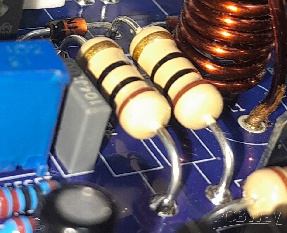
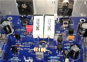
Figure 1: Example of an air-gap between the 1W resistors and the PCB.
The four fuse clips and the four male spade terminals can be installed next, followed by the low-profile ceramic and film capacitors. RV1 and RV2 can also be installed at this point, and as both are 1k, it doesn't matter which one is installed where. RV2 should be installed so the "screw" matches the "screw" position of the footprint on the PCB (the screw faces to the left of the board). Intall the TO-92 transistors next (Q1 - Q4, Q12 and Q13). All the electrolytic capacitors can be installed observing correct polarity (C1 and C3 are non-polorised and can be installed either way around) followed by the TO-126 transistors (Q5 - Q7), and the 5W resistors (R21 - R24) again observing an "air-gap" between the device and the PCB. The next part of the construction will involve winding and installing the coil (L1).
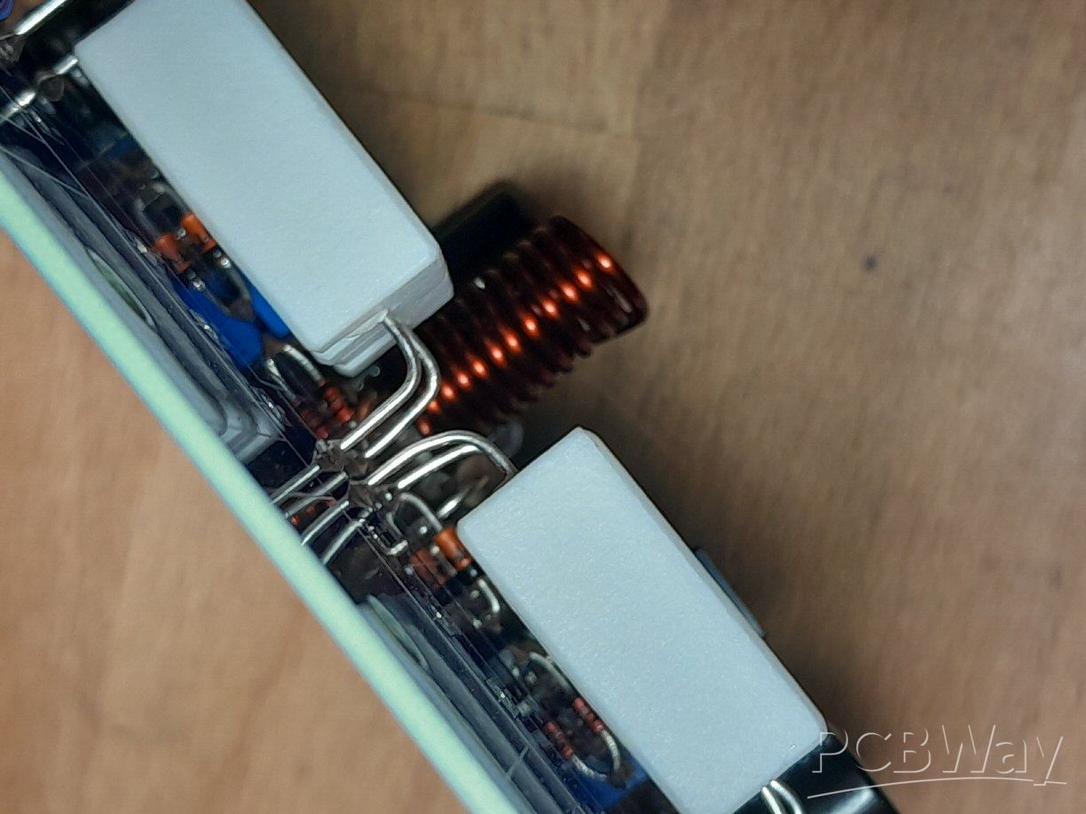
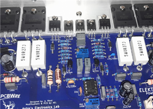
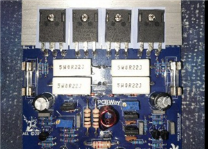
Figure 2: Example of an air-gap between the 5W output resistors and the PCB.
Winding the Coil
This will require a length of 1.25mm diameter enamel copper wire (approx. 430mm long). Start by scraping (or sanding) the enamel coating off one end about 10mm in length (or use some form of chemical to disolve the coating). You want to see shiney copper when looking at it from all angles. Once you think you scraped enough, scrape some more! The coating is kind of a pain to fully get off so solder will adhere to it. Begin winding the coil 1mm above the scraped portion around a 6.5mm drill bit shank, with a total of 12 turns tightly wound next to each other. Once you reach the 12th winding, carefully remove the coil from the drill bit. Bend the "start" end (the 10mm scraped portion) at right angles to the coil. Fold the other end over at right angles to the coil close to the body of the windings. Trim the end of this so it's length is the same as the "start" end and again, scrape or sand off about 10mm length of the enamel coating to expose the copper. Once you have done this, you should have something that looks like the below photo.
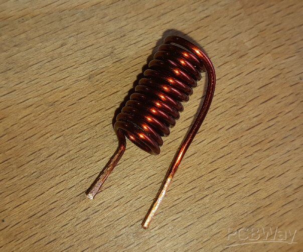
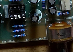
Figure 3: Once the coil is wound and bent, it should look like this.
The coil can now be installed in the PCB at L1 location and soldered. Note, this may take a fair amount of heat to get the solder to "take" properly, so be patient. There's a fair bit of copper in the traces being soldered to and the wire itself that are going to act as a "heatsink" diverting heat away from the joints. Once soldered, using a multimeter in resistance mode, measure across R26. You should see close to 0 ohm, indicating a dead short. If you see 10 ohm, the coil is not soldered properly and will require more attention. Once this is complete, you can now move on to the hardest part, which is drilling the heatsink bracket.
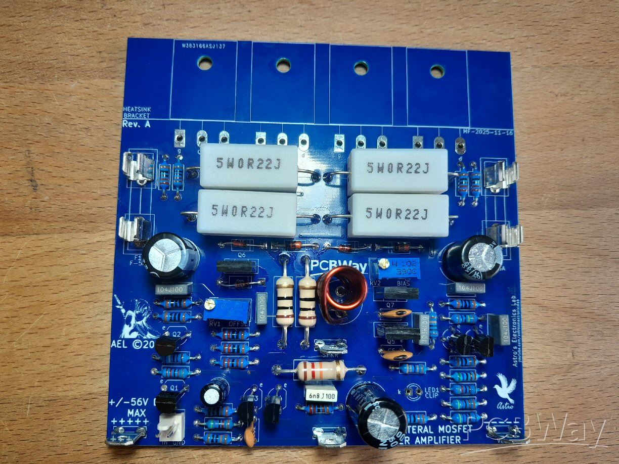
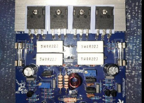
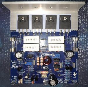
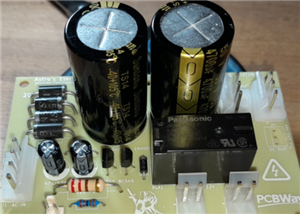
Figure 4: What the partially assembled PCB should look like.
Heatsink Bracket
A drilling guide for the transistor holes is provided below. The L-bracket itself is a 100mm length of 32mm x 32mm x 3mm thickness aluminium stock, and I bought mine pre-cut from Hardware Master on eBay. I will leave it up to you how and where to drill the holes on the heatsink face of the bracket which will be dependant on what heatsink you are connecting the module to.
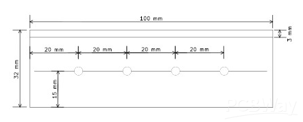
Figure 5: Drilling guide for the L-bracket. Each transistor hole should be drilled to 3.5mm to accomodate for any alignment issues with manual drilling.
Final Assembly
Now, it is time to intall the bracket and the MOSFETs to the module. Begin by bending each leg of each MOSFET at 90 degrees about 1mm from the shank of the device (the part where the leg widens before entering the device).
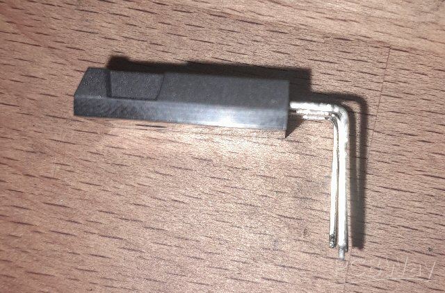
Figure 6: Example of how the MOSFET's legs are bent prior to installation in the PCB.
Install each transistor in the correct locations with TO-3P isolation washers between the transistor and the bracket using a 15mm long M3 screw and nut. Get all four transistors loosely mounted (but not tight) in the PCB and bracket, the isolation washers can be "massaged" around until they are straight. Turn the assembly over and finger tighten the screws and nuts adjusting the bracket periodically so it remains square with the PCB (nothing worse than a wonky looking PCB!). The screws can now be tightened so they're snug, you don't have to kill it. It's always a good idea to tighten the screws BEFORE soldering as this will prevent undue stress being placed on the transistor cracking it. Finally, solder each transistor in and trim off the excess lead length. That will complete assembly, now it's on to testing!
Testing
Never test any amplifier without it being connected to a suitable heatsink; ensure the module is attached to a heatsink before testing. Before hooking the amplifier up to a suitable supply (I would suggest a dual bench supply with current limiting), rotate RV2 full counter-clockwise. This will set minimum bias; failure to do this will provide excess amounts of current in the output stage for no reason, possibly leading to failure. If you're using a bench supply, install the two 5A quick-blow fuses at F1 and F2. If you're using the power supply intended for the amplifier (maximum +/-56VDC), temporarily install a 100 ohm 5W resistor across each fuse holder with the fuses removed.
Hook up the supply leads to their correct locations and power on the circuit and (on a bench supply current limited to around 200mA) look for any excessive current draw. There should be no more than about 15mA; if it reaches limiting, there's a problem. If you're not using a bench supply, gentally touch each 100 ohm resistor in turn checking for excessive heating. If they're getting hot, or even smoking, it's drawing too much current. Switch off and correct the problem.
Assuming it's passed the "smoke test", measure the output of the amplifier at "SPKR" and "GND" with a multimeter set to volts DC. The offset shouldn't be any higher than +/-40mV. If you see one of the supply rails, something is either not connected to the module correctly or there is a faulty component/solder joint. Check your work and correct the problem. Also confirm BOTH supply rails to the amplifier are roughly the same voltage with respect to "GND". If they differ wildly, there's you're problem!
RV1 can now be adjusted to "trim-out" the excess DC. Start by turning the pot in one direction observing the reading, if it starts to incress, rotate the pot in the other direction until you see close to 0V (+/-2mV). If you're using a bench supply, you can now start rotating RV2 clockwise until you see a current draw of around 40mA. Let the amplifier thermally stablise for a few minutes, and check/adjust the bias again. If you're not using a bench supply, connect the multimeter in volts DC mode across one of the 100 ohm 5W resistors and measure the voltage drop. Adjust RV2 clockwise until you see around 4V DC on the multimeter which equates to a quiecent current of roughly 40mA. Let the amplifier thermally stablise and check/adjust the bias as necessary.
That concludes the initial testing. The only thing left to do is install the two fuses (if you haven't done so already), provide an input signal and connect it to a speaker and give it a listening test. Enjoy!
Link to my YouTube video constructing this amplifier:
150W Lateral MOSFET Power Amplifier
Project images are for reference only. Actual production is based on the manufacturing files on the project page.
Please review the designer's notes (e.g., PCB thickness) and select the appropriate options.
PCBWay is not responsible
for issues caused by unsuitable parameter selections.
For more important ordering information, please refer to
Read More


Raspberry Pi 5 7 Inch Touch Screen IPS 1024x600 HD LCD HDMI-compatible Display for RPI 4B 3B+ OPI 5 AIDA64 PC Secondary Screen(Without Speaker)
BUY NOW


- Comments(0)
- Likes(2)
- 1 USER VOTES
- YOUR VOTE 0.00 0.00

-
10design
-
10usability
-
10creativity
-
10content
More by Astro's Electronics Lab
-
 AEL-2011 Power Supply Module
NOTE: THIS INVOLVES MAINS WIRING AND MAINS POTENTIAL. IF YOU ARE NOT CONFIDENT IN HANDLING MAINS WIR...
AEL-2011 Power Supply Module
NOTE: THIS INVOLVES MAINS WIRING AND MAINS POTENTIAL. IF YOU ARE NOT CONFIDENT IN HANDLING MAINS WIR...
-
 AEL-2011 50W Power Amplifier
IntroductionThis little amplifier module measuring 100mm by 100mm is capable of producing 50W into 8...
AEL-2011 50W Power Amplifier
IntroductionThis little amplifier module measuring 100mm by 100mm is capable of producing 50W into 8...
-
 Elektor PA300 300W Power Amplifier
NOTE: This is an intermediate project; DO NOT attempt this as your first project if you’re a novice....
Elektor PA300 300W Power Amplifier
NOTE: This is an intermediate project; DO NOT attempt this as your first project if you’re a novice....
-
 Simple 45W Discrete Power Amplifier
This simple amplifier is capable of producing up to 45W in to 8 ohms at the specified supply rails o...
Simple 45W Discrete Power Amplifier
This simple amplifier is capable of producing up to 45W in to 8 ohms at the specified supply rails o...
-
 555 Timer 12VDC Motor Speed Controller
Using a 555 timer and PWM (Pulse-Width Modulation), by varying its duty-cycle, we can vary the speed...
555 Timer 12VDC Motor Speed Controller
Using a 555 timer and PWM (Pulse-Width Modulation), by varying its duty-cycle, we can vary the speed...
-
 Headphone Adaptor for Power Amplifiers
Add a headphone socket to any existing stereo amplifier that doesn't have one. This L-pad attenuator...
Headphone Adaptor for Power Amplifiers
Add a headphone socket to any existing stereo amplifier that doesn't have one. This L-pad attenuator...
-
 Soft-Start Circuit for Toroidal Transformers
WARNING: This project is connected to mains line voltage during its entire operation. This project s...
Soft-Start Circuit for Toroidal Transformers
WARNING: This project is connected to mains line voltage during its entire operation. This project s...
-
 AEL-50B Simple 50W Power Amplifier
Need a simple power amplifier to drive a loudspeaker that doesn't require any messy set-ups to get g...
AEL-50B Simple 50W Power Amplifier
Need a simple power amplifier to drive a loudspeaker that doesn't require any messy set-ups to get g...
-
 150W Lateral MOSFET Power Amplifier
NOTE 1: This project is not intended for beginners. It is intended for someone with a medium underst...
150W Lateral MOSFET Power Amplifier
NOTE 1: This project is not intended for beginners. It is intended for someone with a medium underst...
-
 Elektor Austereo 5W Stereo Amplifier
IntroductionThis little stereo amplifier will happily produce 5W RMS per-channel into 8 ohms and fea...
Elektor Austereo 5W Stereo Amplifier
IntroductionThis little stereo amplifier will happily produce 5W RMS per-channel into 8 ohms and fea...
-
 Simple NE5532 Stereo Preamplifier
Need a simple stereo preamplifier for a set of power amplifiers? Here's the solution. Based on an NE...
Simple NE5532 Stereo Preamplifier
Need a simple stereo preamplifier for a set of power amplifiers? Here's the solution. Based on an NE...
-
 NE5534 5W Utility Power Amplifier PSU
This power supply was intended for the NE5534 power amplifier project:https://www.pcbway.com/project...
NE5534 5W Utility Power Amplifier PSU
This power supply was intended for the NE5534 power amplifier project:https://www.pcbway.com/project...
-
 LM386 Amplifier For Electret Microphone (Bullhorn)
This little circuit was originally designed to have an electret microphone insert connected at the i...
LM386 Amplifier For Electret Microphone (Bullhorn)
This little circuit was originally designed to have an electret microphone insert connected at the i...
-
 NE5534 5W Utility Power Amplifier
I needed a small amplifier to drive a pair of bookshelf speakers for testing other audio gear, such ...
NE5534 5W Utility Power Amplifier
I needed a small amplifier to drive a pair of bookshelf speakers for testing other audio gear, such ...
-
 Guitar Practice Amplifier (0.5W)
This little amplifier will happily drive a 4 - 8 ohm speaker to pretty loud levels, complete with ov...
Guitar Practice Amplifier (0.5W)
This little amplifier will happily drive a 4 - 8 ohm speaker to pretty loud levels, complete with ov...
-
 100mW Utility Amplifier
Need a small amplifier to amplify a radio front-end, or similar? This will do it! It produces up to ...
100mW Utility Amplifier
Need a small amplifier to amplify a radio front-end, or similar? This will do it! It produces up to ...
-
 Car Alarm Deterrent Flasher
We've all seen them; a bright red flashing light on someone's car's dash board to indicate there is ...
Car Alarm Deterrent Flasher
We've all seen them; a bright red flashing light on someone's car's dash board to indicate there is ...
-
 555 Timer Bi-Stable AC Mains Switch
WARNING: THIS CIRCUIT IS CONNECTED DIRECTLY TO THE MAINS SUPPLY AND CAN BE DANGEROUS. EXTREME CARE S...
555 Timer Bi-Stable AC Mains Switch
WARNING: THIS CIRCUIT IS CONNECTED DIRECTLY TO THE MAINS SUPPLY AND CAN BE DANGEROUS. EXTREME CARE S...
-
Programmable Mist Maker - XIAO / QT PY Extension
1130 2 1 -
RadioHAT - Raspberry Pi radio development platform
939 0 2 -
-
-
-
-
ARPS-2 – Arduino-Compatible Robot Project Shield for Arduino UNO
3365 0 6 -
A Compact Charging Breakout Board For Waveshare ESP32-C3
3980 3 8 -
AI-driven LoRa & LLM-enabled Kiosk & Food Delivery System
4369 2 2


