


AEL-2011 50W Power Amplifier
Introduction
This little amplifier module measuring 100mm by 100mm is capable of producing 50W into 8 ohms and up to 70W into 4 ohms. With adjustable DC offset and bias as well as featuring short circuit protection; this makes for a very stable, rugged and reliable amplifier. It's suitable for use with music instruments, such as bass and guitar, or as the basis for a stereo amplifier (requires two modules).
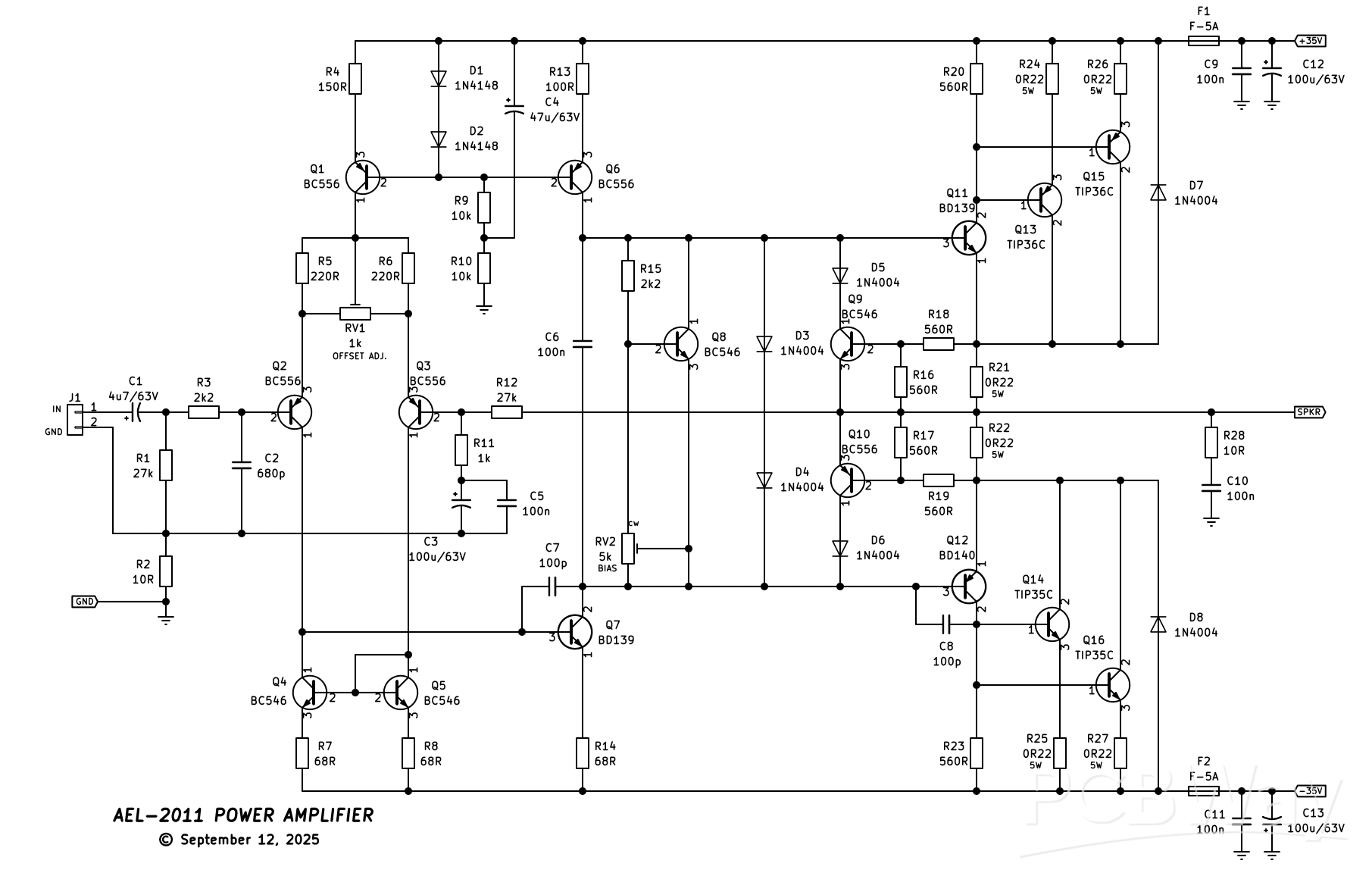
This was designed in September of 2011 (hence why it's called the AEL-2011!) and features both a constant current source (Q1) and current mirror (Q4/Q5) to the long-tail input pair (Q2/Q3). This will ensure the lowest possible distortion at the input stage. A constant current source (Q6) is also provided for the voltage amplification stage (Q7). A VI (voltage/current) limiter is included (D3 - D6, Q9 and Q10 and R16 to R19) as a basic short circuit protection if the output was shorted to ground. This will limit the current in the output stage to around 8A and will blow the line fuses (F1/F2) if the short is allowed to continue, protecting the output stage from catastophic destruction. I wouldn't advocate intentionally shorting the output to test this, though. D7 and D8 provide "fly-back" during a short, shunting current back to the supply rails away from the output transistors.
The output topology is a Class-AB Sziklai complementary feedback pair Q11, Q13 and Q15 on the positive side and Q12, Q14 and Q16 on the negative side. R28 and C10 form a Zobel network to ensure the amplifier remains stable and doesn't go in to high frequency oscillation.
A suitable power supply has been designed to go with this, available here, which is capable of powering two of these modules.
Specifications (tested at +/-30V DC)
Power output: 40W @ 8 ohm; 51W @ 4 ohm
Frequency response: 15Hz - 25kHz
THD: (not measured)
Stability: Unconditional
Construction
Construction is relatively straight forward as all components mount on a single PCB. Begin assembly by installing all the 1/2W metal film resistors, followed by the diodes. The four fuse clips can now be installed, taking note of the orientation of the tang of the clip. This faces outwards away from the fuses. Installing them the other way, or backwards, will result in the fuses not fitting in the clips correctly. Next, install the four 6.3mm male spade terminals. I bought mine from Jaycar and they have a 5mm pin pitch with 1mm diameter pins. You can get similar ones from Digikey or Altronics, however the pin diameter maybe larger (up to 1.4mm). This is easy to get around by taking a small file to the pins and taking of enough material for them to fit through the PCB holes.
J1 can be installed now followed by the ceramic and MKT capacitors. Install all the electrolytic capacitors taking note of the correct polarity. All the small signal transistors (BC546/BC556) can be installed, followed by the TO-126 transistors (BD139/BD14) taking note that Q8 and Q11 are in close proximity to each other and must be physically touching.
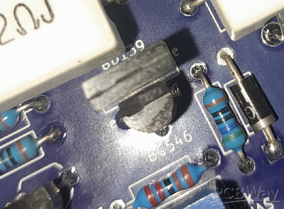
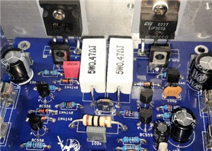
Figure 1: This photo shows Q8 and Q11 "butting-up" to each other. This ensures thermal tracking of the VBE multiplier to help prevent thermal run-away conditions.
Q8 is the VBE multiplier (or bias speader) and Q11 is one of the drivers. Q8 tracks the temperature of Q11 and lowers the bias current accordingly to prevent thermal run-away. You can, before installing Q8 and Q11, place the two together in the correct orientation with a bit of heatshrink over the top shrunk down to make "one" component. This may prove a bit fiddly, but can be done. Another way is to put a zap-strap (zip-tie) around both transistors, prior to soldering, zipped up tightish and then soldered. In general, through my testing, as long as Q8 is somewhat touching Q11, it's fine with no further securing needed.
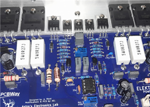
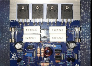
Now, the 0.22 ohm 5W resistors can be installed providing a small "air gap" between the component and the PCB. This ensures good airflow when the component starts to heat up and prevents charring of the PCB.
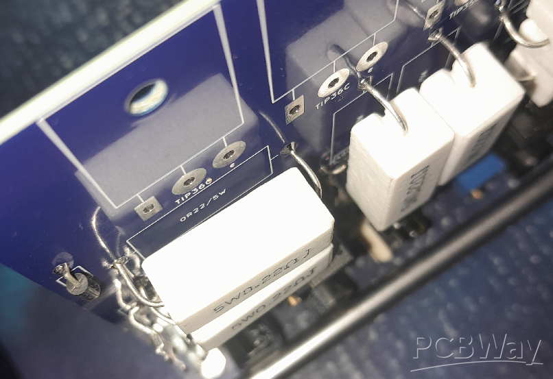
Figure 2: Example of an "air gap" of the 5W resistors. This helps with air flow around the component and prevents charring of the PCB when they get hot.
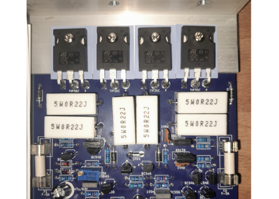
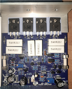
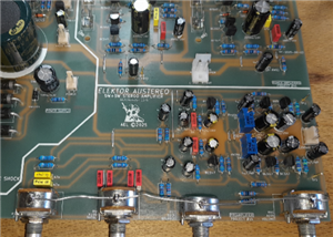
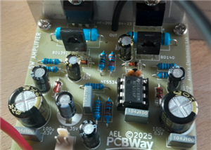
Once you've reached this part of the construction, you should have something that looks similar to the photo below.
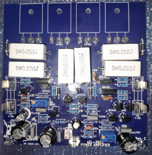
Figure 3: The assembled PCB without the output transistors installed. This is what you should have once you get to this part of the assembly stage.
Now, comes the manual hardware part (fun!). Before the output transistors can be mounted, the 32mm x 32mm x 3m 100mm long aluminium L-bracket needs to be drilled. A drilling guide is shown below and I will leave it up to you how and where you want to drill the holes for the heatsink mounting face of the bracket. This all depends on your choice of heatsink, fin spacing, etc.. If you want to mount two modules to the same heatsink/bracket, a 200mm long bracket is required, and the drilling guide duplicated. All measurements are 20mm apart from the edge of the bracket and each transistor mounting hole.
[drilling guide]
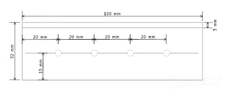
Figure 4: Heatsink bracket drilling guide. This is an aluminium L-bracket measuring 32mm x 32mm x 3mm at 100mm long. If you wish to mount two modules to the same bracket, 200mm long is required and the drilling guide duplicated.
Once the bracket is drilling and de-burred, you can go about bending the legs of each output transistor at 90 degrees so they fit through the holes in the board and the mounting hole of the transistor lines up with the mounting hole in the bracket/PCB. Make sure to use TO-3p insulation washers between the transistors and the bracket to isolate them. Place the bracket on the board and offer up one output transistor, insulation washer and 15mm M3 screw to the PCB lining up the lead holes and mounting hole. Attach an M3 nut on the underside of the board to the screw and loosely tighten. Do NOT solder the transistor(s) yet. Repeat this process until all four output transistors are mounted making sure each is in the correct location (the TIP36C's are on the left of the PCB, the TIP35C's on the right). Making sure the bracket is square with the PCB, each transistor can now be tightened in turn. Snug them up, you don't need to kill them! Rechecking that each transistor is in the correct location, they can now be soldered in and that will complete the construction.
Testing
Before testing begins, first rotate RV2 (the bias pot) fully anti-clockwise (maximum resistance, minimum bias). This will make sure the bias is as low as possible. A variable dual voltage current limited bench supply is useful for testing this module, but is not necessary as will be explained shortly.
If you have a bench supply, install F1 and F2 and connected the supply leads to the spade terminals noting correct polarity with one supply's negative and the other's positive at the GND point. Set current limiting to 100mA of both supplies and the voltage around 15V. Turn the power on and note the current. If it limits to 100mA, there is a problem. Switch off and check for shorts, components in the incorrect places, etc..
Assuming the current doesn't limit (you should see no more than about 8mA at +/-15V), slowly increase the voltage watching the current. If the voltage stops increasing and the current starts to limit, again there is a fault somewhere on the board. If your supply can only produce +/-30V, this is fine, and as long as the current stays around 8 - 10mA, then it is safe to say that you have a functioning module. The bias can now be adjusted until you see around 36mA of current. Allow the amplifier to run for a few minutes and check/adjust the bias again.
If you don't have a bench supply, without the fuses installed, put a 100 ohm 5W wire wound resistor across each fuse holder. Connect a multimeter across one of the resistors set to volts DC and connect the module up to a suitable power supply (+/-35V MAX!). The resistors will limit the current if there is a fault, such as a short, with the module. Apply power and take note of the voltage reading across the resistor. As long as the bias pot is set to minimum, the voltage should not be any higher than around a volt. If it is, or you see close to the supply voltage, there's a fault. Switch off immediately and check for errors.
Assuming everything is OK, slowly wind up RV2 (the bias pot) watching the voltage reading on the multimeter. Once the voltage gets to around 3.6V this will be a quiecent current of around 36mA (3.6 / 100 ohm = 36mA). Allow the amplifier to run for a few minutes and check/adjust the bias again.
Next, switch off and connect the multimeter still set to volts DC with the positive probe on the SPKR terminal, and the negative on GND. Switch on and note the voltage reading. You shouldn't see any more than a few millivolts (maximum of +/-60mV depending on the position of RV1). If it is, or you see a supply rail, there's a fault. Switch off and correct the fault ensuring all components are correctly soldered, in their correct posisions and orientation and there are no solder bridges between components.
If you have around +/-60mV or less of DC offset, slowly rotate RV1 (offset adjust) one direction and if the voltage starts to increase, or doesn't change, rotate it the opposite direction. Continue rotating RV1 until the voltage is around 0V (+/-2mV). If it isn't adjustable, there's an error on the board. Check and correct the issue. This module should work right out of the gate with little-to-no effort.
Assuming all the above tests have passed, the power can be switched off and the 100 ohm 5W resistors removed (if installed) and the two fuses installed in their place. Hook up a suitable input signal to J1 (with the volume LOW!) and a speaker to SPKR and GND, power on and listen for sound/music to issue forth from the speaker. If it does, excellent! You now have a working AEL-2011 power amplifier module, well done! Enjoy!
Link to the video on this power amplifier:
AEL-2011 50W Power Amplifier
*PCBWay community is a sharing platform. We are not responsible for any design issues and parameter issues (board thickness, surface finish, etc.) you choose.


Raspberry Pi 5 7 Inch Touch Screen IPS 1024x600 HD LCD HDMI-compatible Display for RPI 4B 3B+ OPI 5 AIDA64 PC Secondary Screen(Without Speaker)
BUY NOW


- Comments(0)
- Likes(3)
More by Astro's Electronics Lab
-
 AEL-2011 Power Supply Module
NOTE: THIS INVOLVES MAINS WIRING AND MAINS POTENTIAL. IF YOU ARE NOT CONFIDENT IN HANDLING MAINS WIR...
AEL-2011 Power Supply Module
NOTE: THIS INVOLVES MAINS WIRING AND MAINS POTENTIAL. IF YOU ARE NOT CONFIDENT IN HANDLING MAINS WIR...
-
 AEL-2011 50W Power Amplifier
IntroductionThis little amplifier module measuring 100mm by 100mm is capable of producing 50W into 8...
AEL-2011 50W Power Amplifier
IntroductionThis little amplifier module measuring 100mm by 100mm is capable of producing 50W into 8...
-
 Elektor PA300 300W Power Amplifier
NOTE: This is an intermediate project; DO NOT attempt this as your first project if you’re a novice....
Elektor PA300 300W Power Amplifier
NOTE: This is an intermediate project; DO NOT attempt this as your first project if you’re a novice....
-
 Simple 45W Discrete Power Amplifier
This simple amplifier is capable of producing up to 45W in to 8 ohms at the specified supply rails o...
Simple 45W Discrete Power Amplifier
This simple amplifier is capable of producing up to 45W in to 8 ohms at the specified supply rails o...
-
 555 Timer 12VDC Motor Speed Controller
Using a 555 timer and PWM (Pulse-Width Modulation), by varying its duty-cycle, we can vary the speed...
555 Timer 12VDC Motor Speed Controller
Using a 555 timer and PWM (Pulse-Width Modulation), by varying its duty-cycle, we can vary the speed...
-
 Headphone Adaptor for Power Amplifiers
Add a headphone socket to any existing stereo amplifier that doesn't have one. This L-pad attenuator...
Headphone Adaptor for Power Amplifiers
Add a headphone socket to any existing stereo amplifier that doesn't have one. This L-pad attenuator...
-
 Soft-Start Circuit for Toroidal Transformers
WARNING: This project is connected to mains line voltage during its entire operation. This project s...
Soft-Start Circuit for Toroidal Transformers
WARNING: This project is connected to mains line voltage during its entire operation. This project s...
-
 AEL-50B Simple 50W Power Amplifier
Need a simple power amplifier to drive a loudspeaker that doesn't require any messy set-ups to get g...
AEL-50B Simple 50W Power Amplifier
Need a simple power amplifier to drive a loudspeaker that doesn't require any messy set-ups to get g...
-
 150W Lateral MOSFET Power Amplifier
NOTE 1: This project is not intended for beginners. It is intended for someone with a medium underst...
150W Lateral MOSFET Power Amplifier
NOTE 1: This project is not intended for beginners. It is intended for someone with a medium underst...
-
 Elektor Austereo 5W Stereo Amplifier
IntroductionThis little stereo amplifier will happily produce 5W RMS per-channel into 8 ohms and fea...
Elektor Austereo 5W Stereo Amplifier
IntroductionThis little stereo amplifier will happily produce 5W RMS per-channel into 8 ohms and fea...
-
 Simple NE5532 Stereo Preamplifier
Need a simple stereo preamplifier for a set of power amplifiers? Here's the solution. Based on an NE...
Simple NE5532 Stereo Preamplifier
Need a simple stereo preamplifier for a set of power amplifiers? Here's the solution. Based on an NE...
-
 NE5534 5W Utility Power Amplifier PSU
This power supply was intended for the NE5534 power amplifier project:https://www.pcbway.com/project...
NE5534 5W Utility Power Amplifier PSU
This power supply was intended for the NE5534 power amplifier project:https://www.pcbway.com/project...
-
 LM386 Amplifier For Electret Microphone (Bullhorn)
This little circuit was originally designed to have an electret microphone insert connected at the i...
LM386 Amplifier For Electret Microphone (Bullhorn)
This little circuit was originally designed to have an electret microphone insert connected at the i...
-
 NE5534 5W Utility Power Amplifier
I needed a small amplifier to drive a pair of bookshelf speakers for testing other audio gear, such ...
NE5534 5W Utility Power Amplifier
I needed a small amplifier to drive a pair of bookshelf speakers for testing other audio gear, such ...
-
 Guitar Practice Amplifier (0.5W)
This little amplifier will happily drive a 4 - 8 ohm speaker to pretty loud levels, complete with ov...
Guitar Practice Amplifier (0.5W)
This little amplifier will happily drive a 4 - 8 ohm speaker to pretty loud levels, complete with ov...
-
 100mW Utility Amplifier
Need a small amplifier to amplify a radio front-end, or similar? This will do it! It produces up to ...
100mW Utility Amplifier
Need a small amplifier to amplify a radio front-end, or similar? This will do it! It produces up to ...
-
 Car Alarm Deterrent Flasher
We've all seen them; a bright red flashing light on someone's car's dash board to indicate there is ...
Car Alarm Deterrent Flasher
We've all seen them; a bright red flashing light on someone's car's dash board to indicate there is ...
-
 555 Timer Bi-Stable AC Mains Switch
WARNING: THIS CIRCUIT IS CONNECTED DIRECTLY TO THE MAINS SUPPLY AND CAN BE DANGEROUS. EXTREME CARE S...
555 Timer Bi-Stable AC Mains Switch
WARNING: THIS CIRCUIT IS CONNECTED DIRECTLY TO THE MAINS SUPPLY AND CAN BE DANGEROUS. EXTREME CARE S...
-
Programmable Mist Maker - XIAO / QT PY Extension
404 0 0 -
RadioHAT - Raspberry Pi radio development platform
316 0 1 -
-
-
-
-
ARPS-2 – Arduino-Compatible Robot Project Shield for Arduino UNO
2867 0 6 -
A Compact Charging Breakout Board For Waveshare ESP32-C3
3370 3 8 -
AI-driven LoRa & LLM-enabled Kiosk & Food Delivery System
3689 2 2


