


Elektor Austereo 5W Stereo Amplifier
Introduction
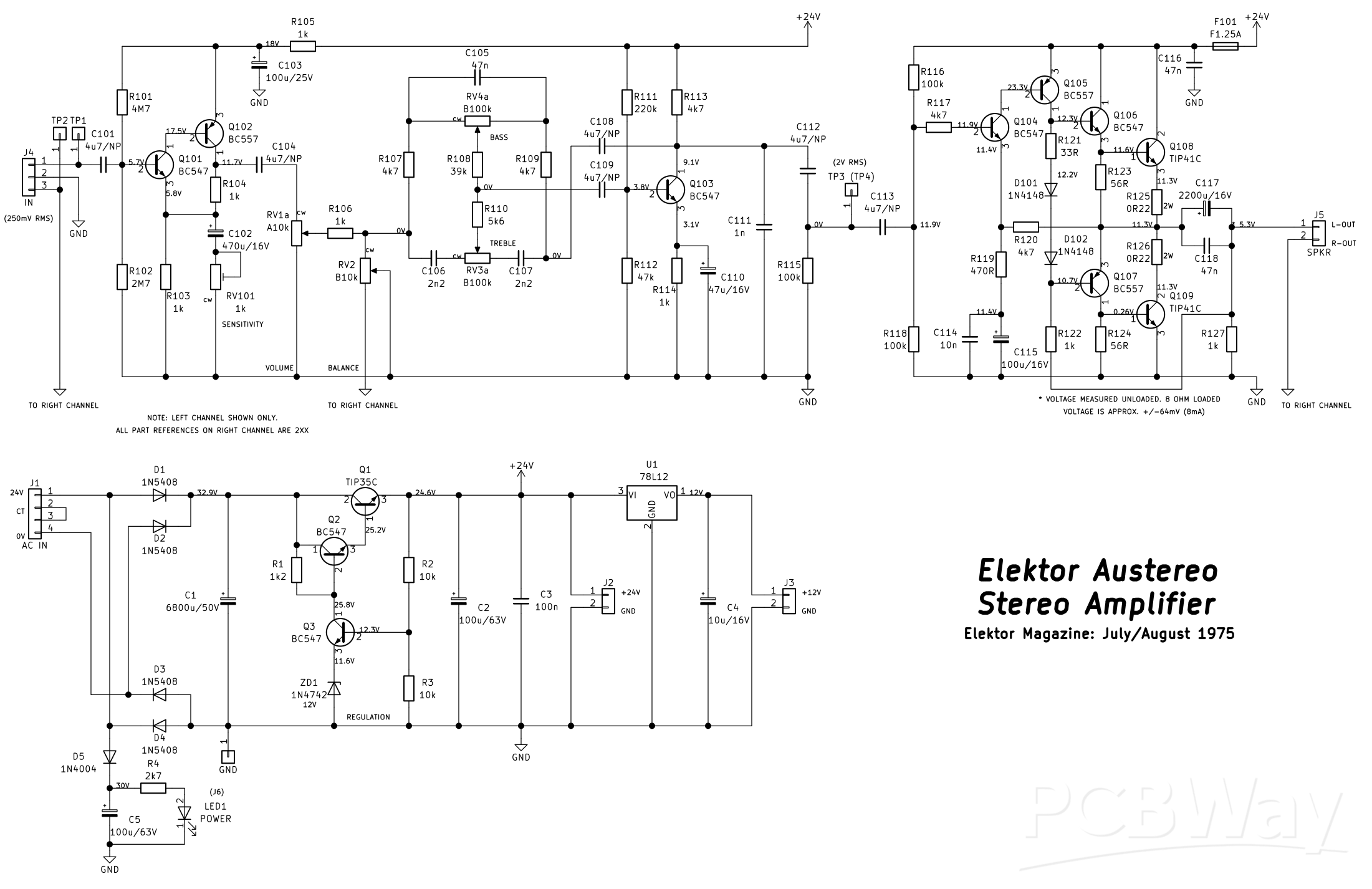
This little stereo amplifier will happily produce 5W RMS per-channel into 8 ohms and features volume, balance and tone controls. This is based on an article called the "Austereo" published in the July/August 1975 issue of "Elektor" magazine; it has just been "modernised" with newer components than the ones used in the '70's, and some values of capacitors have changed from the original. This uses project 44 (preamplifier) and 46 (power amplifier) with a modified project 48 (the power supply).
The power supply runs off of a 24V AC at at least 2A current capability power transformer, and uses a series-pass regulator circuit (Q1) to produce 24V DC for both the power amplifiers and the preamplifier. This regulator utilises an error amplifier (Q3), voltage reference of 12V (ZD1) and a voltage divider on the error amplifier's base comprising of R2 and R3 to effectively double the output voltage of the reference voltage. The output stage of this regulator uses a Darlington configuration comprising of Q2 together with Q1 which increases the effective gain of just using a single power output transistor. The regulation isn't exactly accurate, and will start to drop off in voltage as more current is demanded; but it should be OK up to 1A of current draw.
There are two PCB header connectors for DC output (J2 and J3); a 24V and a 12V one. The extra 24V can be used to power another preamplifier (such as a phono RIAA preamplifier), and the 12V could be use to power an input selector relay board. If you don't need either of these outputs, the header connectors can be omitted and U1 and C4 (the 10uF 16V capacitor) can also be excluded. There is also a provision on the PCB to power an indicator LED, such as a "power" LED via J6. The header is intended for an off-board mounted LED, like a front panel mounted indicator. You can, also choose to omit the header and install the LED directly on to the PCB, or omit it all together.
The "GND" connection close to C1 is both the chassis ground and the amplifier's speaker output ground, and must be connected to this point in order to get any sound output. Do not connect the speaker output grounds to anywhere else other than the large "GND" pad near the filter capacitor C1, or the chassis ground.
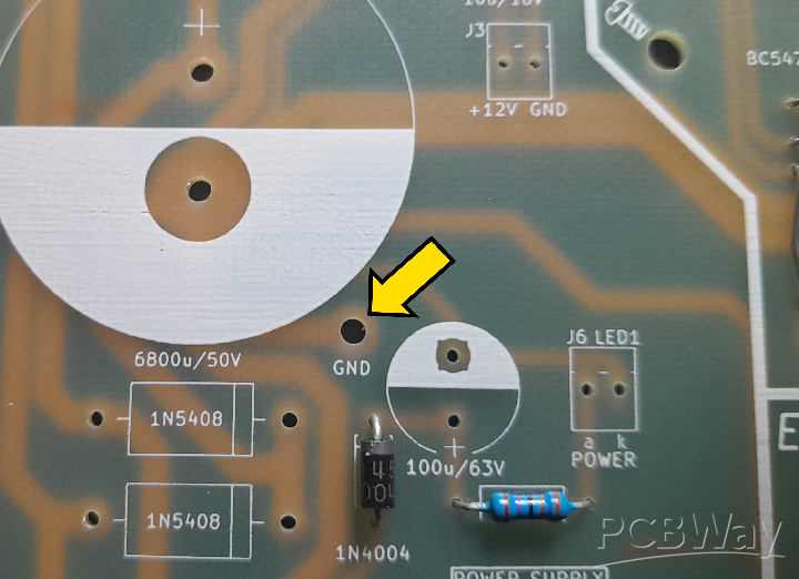
Figure 1 - ground point location on the PCB
The power amplifiers themselves are a single-supply based quasi-complimentary output symmetry design with one caveat. If no load is connected to the outputs (ie. speakers), there will be approximately 5.3V DC offset from each amplifier. This is due to the design of the self-biasing circuitry, including the bootstrapping of the output using R122/R222 and R127/R227. This, however, is normal operation, and this voltage will fall to around +/-83mV when an 8 ohm set of speakers are connected. This is a minimal DC offset presented to the speakers and works out to about 10mA of DC current flowing through the voice coils all the time. This should not affect most loudspeakers, so isn't much of a concern; it takes a lot more DC current to overheat the voice coils before they're destroyed. However, do not connect any loudspeaker to this amplifier after assembly before seeing the "Final testing" section.
The input sensitivity of the preamplifier can be adjusted (via RV101/RV201) from as low as 5mV RMS to above 250mV RMS, but in this construction project, the input sensitivity will be adjusted to around 250mV RMS. This should be suitable enough for most audio input sources (except CD players, as these can have an output far exceeding 2V RMS!). If you want to use a CD player as an input, you'll have to incorporate an L-pad atennuator which is beyond the scope of this project, but can easily be researched online. A good place to start is Rod Elliot's "ESP" sound pages https://sound-au.com/. But, who uses CDs anymore, right?!
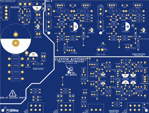
The entire amplifier and power supply are built on a single single-sided PCB measuring 132mm by 172mm, and I chose single-sided as it's easier to change failed components, or make modifications, because it can be challenging at the best of times to desolder components from a double-sided PCB. This just means various link wires (12 in total) have to be implemented on the PCB to make various connections in the circuit that would be easier to do with a double-sided PCB eliminating the links; that's just the nature of single-sided PCBs!
Specifications
Quiescent/Idle current (LED1 not installed): 43mA unloaded; 62mA loaded (6 ohm test speakers)
Preamplifier:
Input sensitivity: 250mV RMS
Output swing: 2V RMS @ 250mV RMS input sensitivity
Frequency response (tone controls flat/centered): 31Hz - 22kHz
Power amplifiers:
Output power (one channel driven): 5.8W RMS into 8 ohms; 9.1W RMS into 4 ohms before clipping
Output power (both channels driven): 5.3W RMS into 8 ohms; 8.7W RMS into 4 ohms before clipping
Input sensitivity: 675mV RMS for full output before clipping
Frequency response: 31Hz - 22kHz
DC offset (loaded): +/-83mV @ 8 ohms; +/-41mV @ 4 ohms
Before commencing construction
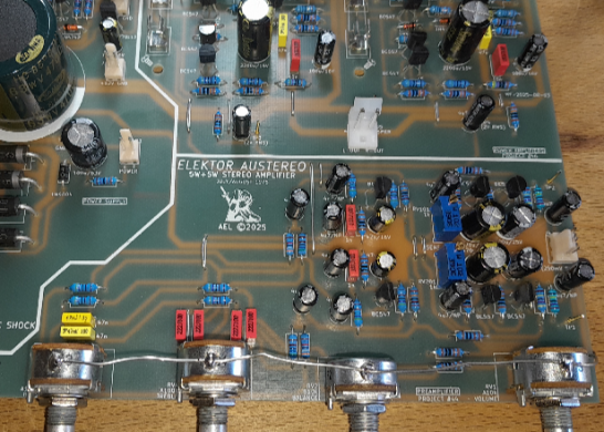
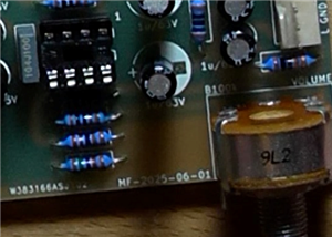
There is an error on the silkscreen of the PCB (see photo below). R112/R212 (the two 4k7 resistors next to each 220k resistor) are the incorrect value. They should be marked as 47k. Inserting 4k7 will result in distorted output of the preamplifier.
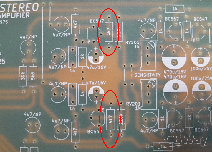
Figure 2 - photo showing the two 4.7k resistors on the PCB that need to be changed to 47k
Construction
I chose the order this is to be assembled in so the module can be assembled flat on a desk slowly installing larger and larger components if you don't have access to a PCB assembly holder tool. Begin by first installing the 12 link wires; you'll need a length (500mm or so, with at least 250mm left over for the "POT GND" strap if you choose to use it) of 0.8mm tinned copper wire to acheive this. Next, install all the 0.25W metal film resistors, followed by D5, D101, D102, D201 and D202. The five PCB pin stakes can be soldered in next at TP1, TP2, TP3, TP4 and TP GND. Install the four fuse clips for F101 and F201 ensuring the little "tang" that's on each clip is oriented so that the fuse will fit in without issue; the tangs face outwards away from the fuses. Do NOT install the fuses at this stage.
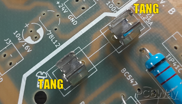
Figure 3 - example of the correct orientation of the fuse clips with the "tangs" facing outwards away from the body of the fuse
D1 to D4 can be installed now as well as R125/R126 and R225/R226 leaving a small gap away from the surface of the PCB (around 3 - 4mm) to allow for air flow and prevent charring of the PCB surface in the event any of these components overheat.
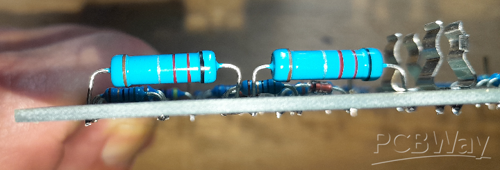
Figure 4 - example of "air-gap" between component body and board surface
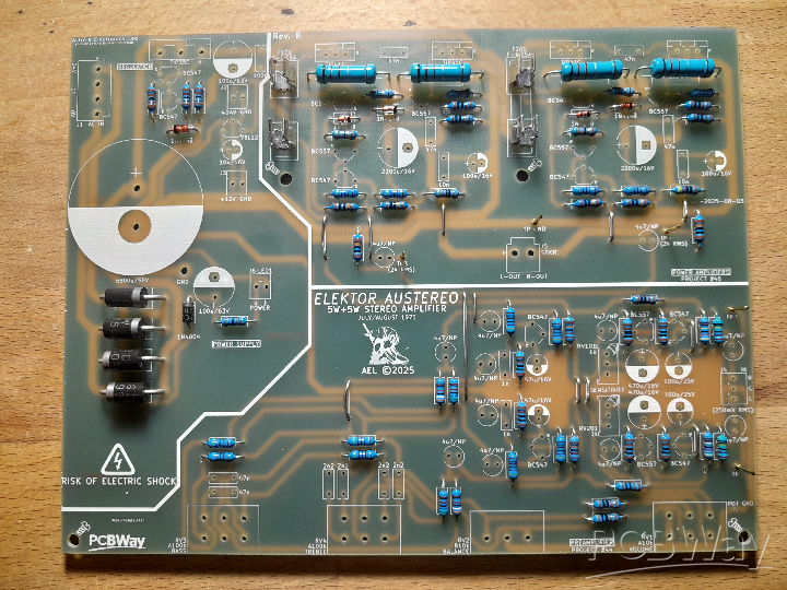
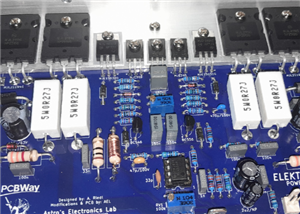
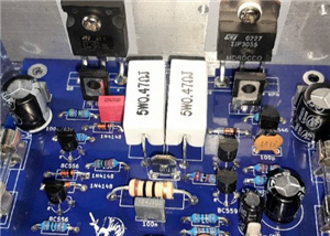
Figure 5 - photo showing complete assembly of resistors and diodes
Install all the MKT capacitors next, followed by RV101 and RV201. The smaller PCB header connectors can now be installed J2, J3, J4 and J6; only install J6 if you're going to use an external LED for LED1, if you're not, this header can be omitted. Install the two larger connectors J1, a 4-pin header and J5, a 2-pin header. You can now install all the smaller electrolytic capacitors (except C1, C117 and C217; these get installed last) making sure of correct polarity (the 4.7uF bipolar capacitors can be inserted any way around as they have no polarity), followed by the small signal transistors (BC547/BC557). If you have chosen to include the optional 12V regulator and header J3, the 78L12 IC can be installed also at this point.
RV1 to RV4 can be installed, and you can choose at this point if you want to use the "POT GND" grounding strap to "ground" the body of each potentiometer to prevent noise pick-up when touching the shafts. If you choose to install this, each pot will need to be filed lightly on the top of each body prior to installation to roughen the surface and allow the solder to "take" to the metal. This may require a bit of heat to acheive, so be paitent. Start at RV4 (the bass pot) attaching the length of 0.8mm tinned copper wire at least 250mm long to the solder "blob" on the pot. Continue attaching the wire to each pot down the line in turn in the same way until you reach RV1 (the volume pot). The loose end of the wire can now be poked though the "POT GND" location on the board and soldered in, trimming off the excess. If the amplifier is going to be installed in a metal enclosure with a good grounded front panel (and the "GND" connection of the PCB is attached to the chassis), the strap can be omitted.
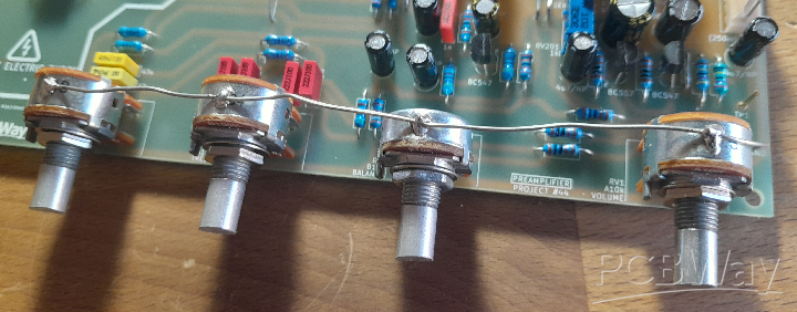
Figure 6 - example of how to do the pot "ground-strap"
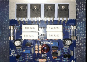
Q1 can be installed, together with Q108, Q109 and Q208 and Q209. The legs of each transistor will have to be bent in such a way to "extend" the metal heatsink mounting surface to be flush with the rear edge of the PCB. See the below photo for reference.
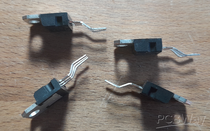
Figure 7 - this should give you some idea of how to bend the legs of the TIP41C transistors so the rear of each transistor is flush with the back edge of the board, allowing it to be bolted to a suitable heatsink
Finally, the large 6,800uF 50V filter capacitor C1 can be installed as well as C117 and C217 observing the correct polarity. In my prototype to write this article, I used a 4,700uF 63V capacitor for C1 as I had a single one knocking about. It really isn't that important to the capacitance, as long as it isn't lower than 4,700uF, and can be higher than 6,800uF. The footprint allows a snap-in capacitor to a maximum diameter of 35mm, so a 10,000uF 50V could also be used. The higher the capacitance, the better the filtering.
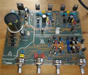
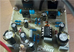
And that completes construction, and you can now move on to testing.

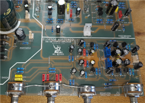
Figure 8 - the fully assembled PCB
Initial Testing
WARNING: THIS NEXT PART INVOLVES MAINS WIRING. IF YOU ARE NOT SURE OF WHAT YOU ARE DOING OR ARE CONFIDENT, DO NOT ATTEMPT ANY MAINS WIRING. FIND A COMPETENT PERSON TO HELP YOU WITH THIS TASK, OR USE A WALL ADAPTER WITH A 24V AC OUTPUT AND AT LEAST 2 AMPS OF CURRENT CAPABILITY. ALSO BE AWARE THERE WILL BE ELEVATED DC VOLTAGES PRESENT ON THE PCB (34V), SO THERE IS RISK OF ELECTRIC SHOCK. ADHERE TO ALL ELECTRICAL SAFETY AND DO NOT COME IN TO CONTACT WITH THESE VOLTAGES.
Before beginning testing, it would be a good idea to check over your work and make sure there are no solder splashes or bridges between components; especially near the exposed copper tracks and adjacent connections. This will save headaches of it "not working", or worse, going up in smoke later.
If you haven't attached the main heatsink to the module yet, attach a small heatsink to Q1 (the 24V regulator series-pass transistor) for the intital tests. Make sure neither fuse is installed. Connect a suitable 24V secondary power transformer or power source to J1. The connector (J1) can be used in several ways. If you're using a single-winding secondary of 24V, each wire attaches to each far end of the plug (the 24V and 0V connections respectively), and the "CT" pins can be ignored. If your transformer has a center-tap (so, 24V, 12V and 0V), the center-tap can be connected to one of the center pins of the plug so you don't have a loose wire just floating around.
However, if you're using a dual-winding transformer with two 12V windings (such as a toroidal transformer), each winding can be connected in series in phase with each other starting with one 12V winding connected to the 24V pin and the end of the winding connected to the CT pin next to it. The final 12V winding can be connected between the second CT pin with the end of the winding terminating at the OV pin.
The secondary current capability of the transformer must be no lower than 2 amps (this includes the half-current of the secondary in series of a toroidal transformer - the series current must be no lower than 2 amps). A transformer with a 3 amp secondary current capability is overkill, but recommended. Make sure an inline fuse is installed on the primary of the recommended current rating as indicated by the manufacturer of the transformer (which can be found in the datasheet for the transformer).
A dim-bulb tester (which is an incandcent or hallogen bulb, that goes in to a normal mains light fixture, connected in series with the incoming live wire from the wall and the live connection input of the device under test) on the primary of the transformer would be a good idea for the first power on, as this is a good way to indicate shorts. A 40W to 60W bulb is fine for testing an amplifier like this. If the bulb glows brightly and doesn't dim out to hardly any brightness, there's a short (either a fault with the board or the transformer itself). Power up the amplifier and check for any signs of visible smoke. If anything starts to release the magic smoke, something is not assembled right. Switch off immediately and check for any errors or faulty components.
Alternatively, a suitable DC power supply capable of at least 30VDC output with current limiting (constant current mode) could be connected to J1 for testing, which would be a lot safer and easier for the above test. With the supply set to 30VDC, the postive output lead would connect to pin 1 of J1 (24V) and the negative to pin 4 (0V). Set the current limit of the power supply to 200mA, or so, and if it goes immediately in to current limiting, then, as above, switch off and check for any errors or faulty components.
Note: your DC supply will go in to constant-current, or current limiting as C1 is charging. This is normal and not an indication of a fault. Allow a few seconds for it to stabalize. If the supply stays in current limiting after five seconds, there's a fault.
Assuming it's passed the "smoke test", measure the voltage with reference to ground (GND) at the regulator output (either J2 +24V point or one end of either fuse holder). This should be close to 24V; if it's not, there is either a bad component or an assembly mistake. If it's 24V (or a little higher, which is fine), you can proceed to measure the 12V output at J3 (if installed). This should be close to 12V (again, a little higher unloaded is fine). Assuming all is well with the above tests, you can now proceed to the "setup" part of the testing.
Setup
Before testing the power amplifiers, it is recommended to set the input sensitivity of each preamplifier first. This is acheived using a DDS (signal generator) and an oscilloscope. If you don't have either, don't worry, I will explain how to set this up "manually" to get it close at the end of this section.
Using a 'scope and signal generator, connect the generator to TP1 (TP2 to do the right channel) and the 'scope using a x1 probe to TP3 (TP4 to do the right channel) and ground them using "TP GND". Set the balance control to dead-center (or as close as possible) and the volume control to maximum. Set the generator's output to a 1kHz sinewave and an amplitude of around 250mV RMS. Switch the amplifier on and adjust the 'scope until you see the signal. If there is no signal or it's distorted, switch off and check your work for solder splashes/bridges or components installed incorrectly. If all is well and you have a nice sinewave on the 'scope, adjust RV101 (RV201 for the right channel) until you get around 2V RMS on the output. Once this is done, the preamplifiers are set to the correct sensitivity. If the output is distorted and doesn't appear to have any gain, make sure the 4k7 resistors mentioned above (R112/R212) are actually 47k.
If you don't have either an oscilloscope or signal generator, you can get it roughly set by measuring the resistance of RV101 and RV201 until you get a reading of around 90 ohms. The trimpots can be tweaked during a listening test to "balance" the sound satisfactorly.
Final testing
Never test ANY power amplifier that isn't attached to a heatsink. Make sure a suitable heatsink is attached to Q1, Q108, Q109 and Q208 and Q209 with suitable insulators and that none of the collectors are electrically connected to the heatsink, or each other. If you're using a DC power supply, keep the current limit set to 200mA for now.
Now, it's time to test the power amplifiers. Start with one channel at a time. Install the 1.25mA fast-blow fuse in to F101 (F201 for the right channel). Connect a DVM (multimeter set to the voltage mode) between the left output (or right output) and ground. Switch on and take note of the output voltage. It should be no higher than 6V. If it is, or you see close to 24V, switch off immediately and check for errors. If all is well, I would suggest connecting an 8 ohm dummy load to the output. Verify the output voltage loaded is no higher than +/-83mV (below 100mV), if it is, there's a problem and it will need to be investigated further. Assuming everything is fine, and you're using a DC supply, the current limit can be increased to no more than 1A.
Using the signal generator connected to TP1 (250mV RMS amplitude from previous test and TP2 for testing the right channel) and the 'scope connected across the dummy load, with the volume control set to minimum and the balance control set to the center position, slowly rotate the volume control clockwise and take note if the signal strength is changing on the 'scope and is a clean sinewave. You will see clipping if you rotate it too high, and it should also be symmetrical. Repeat the above tests on the right-hand channel power amplifier. The results should be the same; however, if the output power varies wildly between the two, check for any component placement issues on the PCB such as resistors in the incorrect locations and bad solder joints (and that RV101/RV201 are correctly "balanced" and that the balance control is dead-center).
Again, if you don't have access to either an oscilloscope and signal generator, all you need is an 8 ohm 10W minimum resistor (or close to 8 ohms) to verify the output voltage of each channel is no higher than +/-83mV (within 100mV maximum). Assuming each amplifier passed these tests, it's now safe to connect the speakers and an input source and do some listening tests. This includes checking the operation of the balance control and tone controls.
And that's it! Enjoy your newly assembled DIY stereo amplifier!
YouTube video showing the build & testing
Elektor Austereo 5W Stereo Amplifier
*PCBWay community is a sharing platform. We are not responsible for any design issues and parameter issues (board thickness, surface finish, etc.) you choose.


Raspberry Pi 5 7 Inch Touch Screen IPS 1024x600 HD LCD HDMI-compatible Display for RPI 4B 3B+ OPI 5 AIDA64 PC Secondary Screen(Without Speaker)
BUY NOW


- Comments(0)
- Likes(2)
- 1 USER VOTES
- YOUR VOTE 0.00 0.00

-
10design
-
10usability
-
10creativity
-
10content
More by Astro's Electronics Lab
-
 AEL-2011 Power Supply Module
NOTE: THIS INVOLVES MAINS WIRING AND MAINS POTENTIAL. IF YOU ARE NOT CONFIDENT IN HANDLING MAINS WIR...
AEL-2011 Power Supply Module
NOTE: THIS INVOLVES MAINS WIRING AND MAINS POTENTIAL. IF YOU ARE NOT CONFIDENT IN HANDLING MAINS WIR...
-
 AEL-2011 50W Power Amplifier
IntroductionThis little amplifier module measuring 100mm by 100mm is capable of producing 50W into 8...
AEL-2011 50W Power Amplifier
IntroductionThis little amplifier module measuring 100mm by 100mm is capable of producing 50W into 8...
-
 Elektor PA300 300W Power Amplifier
NOTE: This is an intermediate project; DO NOT attempt this as your first project if you’re a novice....
Elektor PA300 300W Power Amplifier
NOTE: This is an intermediate project; DO NOT attempt this as your first project if you’re a novice....
-
 Simple 45W Discrete Power Amplifier
This simple amplifier is capable of producing up to 45W in to 8 ohms at the specified supply rails o...
Simple 45W Discrete Power Amplifier
This simple amplifier is capable of producing up to 45W in to 8 ohms at the specified supply rails o...
-
 555 Timer 12VDC Motor Speed Controller
Using a 555 timer and PWM (Pulse-Width Modulation), by varying its duty-cycle, we can vary the speed...
555 Timer 12VDC Motor Speed Controller
Using a 555 timer and PWM (Pulse-Width Modulation), by varying its duty-cycle, we can vary the speed...
-
 Headphone Adaptor for Power Amplifiers
Add a headphone socket to any existing stereo amplifier that doesn't have one. This L-pad attenuator...
Headphone Adaptor for Power Amplifiers
Add a headphone socket to any existing stereo amplifier that doesn't have one. This L-pad attenuator...
-
 Soft-Start Circuit for Toroidal Transformers
WARNING: This project is connected to mains line voltage during its entire operation. This project s...
Soft-Start Circuit for Toroidal Transformers
WARNING: This project is connected to mains line voltage during its entire operation. This project s...
-
 AEL-50B Simple 50W Power Amplifier
Need a simple power amplifier to drive a loudspeaker that doesn't require any messy set-ups to get g...
AEL-50B Simple 50W Power Amplifier
Need a simple power amplifier to drive a loudspeaker that doesn't require any messy set-ups to get g...
-
 150W Lateral MOSFET Power Amplifier
NOTE 1: This project is not intended for beginners. It is intended for someone with a medium underst...
150W Lateral MOSFET Power Amplifier
NOTE 1: This project is not intended for beginners. It is intended for someone with a medium underst...
-
 Elektor Austereo 5W Stereo Amplifier
IntroductionThis little stereo amplifier will happily produce 5W RMS per-channel into 8 ohms and fea...
Elektor Austereo 5W Stereo Amplifier
IntroductionThis little stereo amplifier will happily produce 5W RMS per-channel into 8 ohms and fea...
-
 Simple NE5532 Stereo Preamplifier
Need a simple stereo preamplifier for a set of power amplifiers? Here's the solution. Based on an NE...
Simple NE5532 Stereo Preamplifier
Need a simple stereo preamplifier for a set of power amplifiers? Here's the solution. Based on an NE...
-
 NE5534 5W Utility Power Amplifier PSU
This power supply was intended for the NE5534 power amplifier project:https://www.pcbway.com/project...
NE5534 5W Utility Power Amplifier PSU
This power supply was intended for the NE5534 power amplifier project:https://www.pcbway.com/project...
-
 LM386 Amplifier For Electret Microphone (Bullhorn)
This little circuit was originally designed to have an electret microphone insert connected at the i...
LM386 Amplifier For Electret Microphone (Bullhorn)
This little circuit was originally designed to have an electret microphone insert connected at the i...
-
 NE5534 5W Utility Power Amplifier
I needed a small amplifier to drive a pair of bookshelf speakers for testing other audio gear, such ...
NE5534 5W Utility Power Amplifier
I needed a small amplifier to drive a pair of bookshelf speakers for testing other audio gear, such ...
-
 Guitar Practice Amplifier (0.5W)
This little amplifier will happily drive a 4 - 8 ohm speaker to pretty loud levels, complete with ov...
Guitar Practice Amplifier (0.5W)
This little amplifier will happily drive a 4 - 8 ohm speaker to pretty loud levels, complete with ov...
-
 100mW Utility Amplifier
Need a small amplifier to amplify a radio front-end, or similar? This will do it! It produces up to ...
100mW Utility Amplifier
Need a small amplifier to amplify a radio front-end, or similar? This will do it! It produces up to ...
-
 Car Alarm Deterrent Flasher
We've all seen them; a bright red flashing light on someone's car's dash board to indicate there is ...
Car Alarm Deterrent Flasher
We've all seen them; a bright red flashing light on someone's car's dash board to indicate there is ...
-
 555 Timer Bi-Stable AC Mains Switch
WARNING: THIS CIRCUIT IS CONNECTED DIRECTLY TO THE MAINS SUPPLY AND CAN BE DANGEROUS. EXTREME CARE S...
555 Timer Bi-Stable AC Mains Switch
WARNING: THIS CIRCUIT IS CONNECTED DIRECTLY TO THE MAINS SUPPLY AND CAN BE DANGEROUS. EXTREME CARE S...
-
Programmable Mist Maker - XIAO / QT PY Extension
404 0 0 -
RadioHAT - Raspberry Pi radio development platform
316 0 1 -
-
-
-
-
ARPS-2 – Arduino-Compatible Robot Project Shield for Arduino UNO
2867 0 6 -
A Compact Charging Breakout Board For Waveshare ESP32-C3
3370 3 8 -
AI-driven LoRa & LLM-enabled Kiosk & Food Delivery System
3689 2 2


