


|
KiCADKicad
|
Car Alarm Deterrent Flasher
We've all seen them; a bright red flashing light on someone's car's dash board to indicate there is an active alarm. Some of these lights, however, are dummies. That is, there is no alarm; however, a would-be car theif would have no way of knowing that (until they break in and the car starts making rude noises). You can buy a flasher LED deterrent light that you can install somewhere in the car, find a 12V source and ground, and be done. However, where's the fun in that? Plus, unless you know what you're doing, there's no way to disable the light from flashing while driving, unless you install a switch.
This circuit makes this simple.
Word of caution: this will require you to have a basic understanding of how your car's ignition switch system works, as well as cutting in to the car's wiring and drilling a hole. If your car is under finance or warranty, DO NOT ATTEMPT TO WIRE THIS IN TO YOUR CAR.
With that out of the way, let's discuss how it works. The heart of the circuit is the ICM7555, which is the NE555's CMOS counter-part, and is configured in astable mode. The 680k, 10k and 10uF capacitor between pins 7, 6 and 2 respectively, gives us a roughly 3 second off time (LED not lit), and 100ms on time (LED lit). In all, this makes the LED "blip" once every 3 seconds, or so. The +12V at J1 is connected to a constant 12V supply from the vehicle, GND connects to a suitable metal portion of the vehicle's body, and the "IGN" would connect to the ignition switch (off of the "ACC" (accessories) on position).
To disable the light from flashing while driving, which let's face it, would be both distracting and down-right annoying, we make use of the "IGN" signal by passing it to Q2 (a BC547 transistor) via a 10k base-limiting resistor. When the ignition switch is in the "ACC" position, Q2 will be biased on. This will bring ground up via the emitter to the collector. This passes through R6 to the base of Q1 (a BC557 transistor) turning it on. R5 and R6 form a resistive divider, and R5's job is to keep the base of Q1 slightly reverse-biased when Q2 isn't conducting (ignition off). This prevents Q1 from sporadically conducting due to any noise or interference being picked up at the base (say, you touch it with your finger).
Q1's emitter is connected to the +12V (Vcc), and when conducting will have 12V at its collector, which is connected via R1 (a 100 ohm limiting resistor) to pin 5 of U1, which is the control voltage pin of the 7555. When pin 5 is "high" (at Vcc), the duty cycle will be close to 0, therefore the circuit will not oscillate, preventing the LED from "blipping". When Q1 isn't conducting, pin 5 is potentially just "floating", resulting in the duty cycle being at roughly 50%, allowing it to oscillate normally "blipping" the LED. C2 just keeps the voltage at pin 5 stable, keeping the IC stable.
Finally, C3 provides stabilization as well as bulk filtering especially on long lines from the circuit to the power source (and the vehicle's battery is pretty far from the circuit - at least a couple of meters when all is said and done).
Here's a video link on the PCB being constructed and tested:
Construction:
Construction is straight forward, however I would not install the LED directly on the PCB, as this has to be placed through a hole in the dash somewhere so it's visible outside the car (that is the point after all). I'd solder a couple of feet or wires to the LED back to the pads on the PCB which will allow us to place it somewhere on the dash. You can choose to install the header and plug at J1, or just hard-wire to the board.
To wire this in to the car, I'd suggest mounting this in to a plastic case first so it cannot short on anything metal in the vehicle. Next, you would have to crack open the Simon cowling of the steering wheel to gain access to the back of the ignition switch. BE MINDFUL OF THE AIRBAG IF FITTED AN ADVOID BASHING AROUND THE STEERING COLUMN AREA. Nothing worse than an airbag accidently going off in your face!
Once you have access to the back of the switch, it's trivial with a multimeter to find a constant 12V source between the switch and ground (body of the vehicle), which is usually the center common point of the switch. This is wired to the +12V part of J1. You maybe lucky and find a 12V source somewhere on the switch when it's set to "OFF/LOCK" and disappears when switched to both "ACC" and "ON" (which would require one less wire). Failing that, you'd need to find a second 12V that's only present when the switch is set to "ACC" and "ON" and disappears when switched to "OFF/LOCK". This would connect to IGN of J1 on the PCB. GND simply connects via a wire and eyelet crimp to a convenient bolt/nut on the body of the vehicle that is connected to ground (negative battery terminal of the vehicle). To make the connections to the vehicle, you can use break-in wire joiners available at auto part stores.
Testing is relatively simple, it either flashes, or it doesn't! As soon as the circuit is connected and the vehicle is in "OFF/LOCK", you should see the LED "blip" every 3 seconds or so. Putting the vehicle in "ACC", nothing should happen and the LED should not be flashing. Similarily, with the vechicle running, the LED should not be flashing. If this is the case, it's passed the test!
Current draw of this circuit is relatively small, less than 1mA with the vehicle off (I measured the prototype at around 7-10uA). It will be at approx. 1mA when the ignition is on.

Car Alarm Deterrent Flasher
*PCBWay community is a sharing platform. We are not responsible for any design issues and parameter issues (board thickness, surface finish, etc.) you choose.


Raspberry Pi 5 7 Inch Touch Screen IPS 1024x600 HD LCD HDMI-compatible Display for RPI 4B 3B+ OPI 5 AIDA64 PC Secondary Screen(Without Speaker)
BUY NOW


- Comments(0)
- Likes(0)
More by Astro's Electronics Lab
-
 AEL-2011 Power Supply Module
NOTE: THIS INVOLVES MAINS WIRING AND MAINS POTENTIAL. IF YOU ARE NOT CONFIDENT IN HANDLING MAINS WIR...
AEL-2011 Power Supply Module
NOTE: THIS INVOLVES MAINS WIRING AND MAINS POTENTIAL. IF YOU ARE NOT CONFIDENT IN HANDLING MAINS WIR...
-
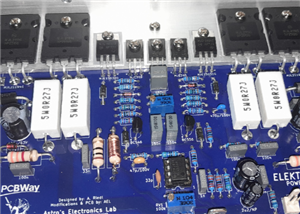
 AEL-2011 50W Power Amplifier
IntroductionThis little amplifier module measuring 100mm by 100mm is capable of producing 50W into 8...
AEL-2011 50W Power Amplifier
IntroductionThis little amplifier module measuring 100mm by 100mm is capable of producing 50W into 8...
-
 Elektor PA300 300W Power Amplifier
NOTE: This is an intermediate project; DO NOT attempt this as your first project if you’re a novice....
Elektor PA300 300W Power Amplifier
NOTE: This is an intermediate project; DO NOT attempt this as your first project if you’re a novice....
-
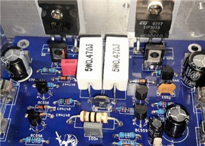 Simple 45W Discrete Power Amplifier
This simple amplifier is capable of producing up to 45W in to 8 ohms at the specified supply rails o...
Simple 45W Discrete Power Amplifier
This simple amplifier is capable of producing up to 45W in to 8 ohms at the specified supply rails o...
-
 555 Timer 12VDC Motor Speed Controller
Using a 555 timer and PWM (Pulse-Width Modulation), by varying its duty-cycle, we can vary the speed...
555 Timer 12VDC Motor Speed Controller
Using a 555 timer and PWM (Pulse-Width Modulation), by varying its duty-cycle, we can vary the speed...
-
 Headphone Adaptor for Power Amplifiers
Add a headphone socket to any existing stereo amplifier that doesn't have one. This L-pad attenuator...
Headphone Adaptor for Power Amplifiers
Add a headphone socket to any existing stereo amplifier that doesn't have one. This L-pad attenuator...
-
 Soft-Start Circuit for Toroidal Transformers
WARNING: This project is connected to mains line voltage during its entire operation. This project s...
Soft-Start Circuit for Toroidal Transformers
WARNING: This project is connected to mains line voltage during its entire operation. This project s...
-
 AEL-50B Simple 50W Power Amplifier
Need a simple power amplifier to drive a loudspeaker that doesn't require any messy set-ups to get g...
AEL-50B Simple 50W Power Amplifier
Need a simple power amplifier to drive a loudspeaker that doesn't require any messy set-ups to get g...
-
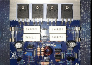 150W Lateral MOSFET Power Amplifier
NOTE 1: This project is not intended for beginners. It is intended for someone with a medium underst...
150W Lateral MOSFET Power Amplifier
NOTE 1: This project is not intended for beginners. It is intended for someone with a medium underst...
-
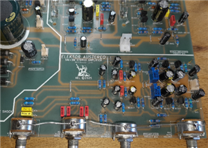 Elektor Austereo 5W Stereo Amplifier
IntroductionThis little stereo amplifier will happily produce 5W RMS per-channel into 8 ohms and fea...
Elektor Austereo 5W Stereo Amplifier
IntroductionThis little stereo amplifier will happily produce 5W RMS per-channel into 8 ohms and fea...
-
 Simple NE5532 Stereo Preamplifier
Need a simple stereo preamplifier for a set of power amplifiers? Here's the solution. Based on an NE...
Simple NE5532 Stereo Preamplifier
Need a simple stereo preamplifier for a set of power amplifiers? Here's the solution. Based on an NE...
-
 NE5534 5W Utility Power Amplifier PSU
This power supply was intended for the NE5534 power amplifier project:https://www.pcbway.com/project...
NE5534 5W Utility Power Amplifier PSU
This power supply was intended for the NE5534 power amplifier project:https://www.pcbway.com/project...
-
 LM386 Amplifier For Electret Microphone (Bullhorn)
This little circuit was originally designed to have an electret microphone insert connected at the i...
LM386 Amplifier For Electret Microphone (Bullhorn)
This little circuit was originally designed to have an electret microphone insert connected at the i...
-
 NE5534 5W Utility Power Amplifier
I needed a small amplifier to drive a pair of bookshelf speakers for testing other audio gear, such ...
NE5534 5W Utility Power Amplifier
I needed a small amplifier to drive a pair of bookshelf speakers for testing other audio gear, such ...
-
 Guitar Practice Amplifier (0.5W)
This little amplifier will happily drive a 4 - 8 ohm speaker to pretty loud levels, complete with ov...
Guitar Practice Amplifier (0.5W)
This little amplifier will happily drive a 4 - 8 ohm speaker to pretty loud levels, complete with ov...
-
 100mW Utility Amplifier
Need a small amplifier to amplify a radio front-end, or similar? This will do it! It produces up to ...
100mW Utility Amplifier
Need a small amplifier to amplify a radio front-end, or similar? This will do it! It produces up to ...
-
 Car Alarm Deterrent Flasher
We've all seen them; a bright red flashing light on someone's car's dash board to indicate there is ...
Car Alarm Deterrent Flasher
We've all seen them; a bright red flashing light on someone's car's dash board to indicate there is ...
-
 555 Timer Bi-Stable AC Mains Switch
WARNING: THIS CIRCUIT IS CONNECTED DIRECTLY TO THE MAINS SUPPLY AND CAN BE DANGEROUS. EXTREME CARE S...
555 Timer Bi-Stable AC Mains Switch
WARNING: THIS CIRCUIT IS CONNECTED DIRECTLY TO THE MAINS SUPPLY AND CAN BE DANGEROUS. EXTREME CARE S...
-
Programmable Mist Maker - XIAO / QT PY Extension
404 0 0 -
RadioHAT - Raspberry Pi radio development platform
316 0 1 -
-
-
-
-
ARPS-2 – Arduino-Compatible Robot Project Shield for Arduino UNO
2867 0 6 -
A Compact Charging Breakout Board For Waveshare ESP32-C3
3370 3 8 -
AI-driven LoRa & LLM-enabled Kiosk & Food Delivery System
3689 2 2


