


Elektor PA300 300W Power Amplifier
NOTE: This is an intermediate project; DO NOT attempt this as your first project if you’re a novice. Do not ask PCBWay to assemble this for you, as they probably won’t read this article for assembly details. This is a DIY (do it yourself) project.
First published October 31, 2025; Updated Feburary 14, 2026
Introduction
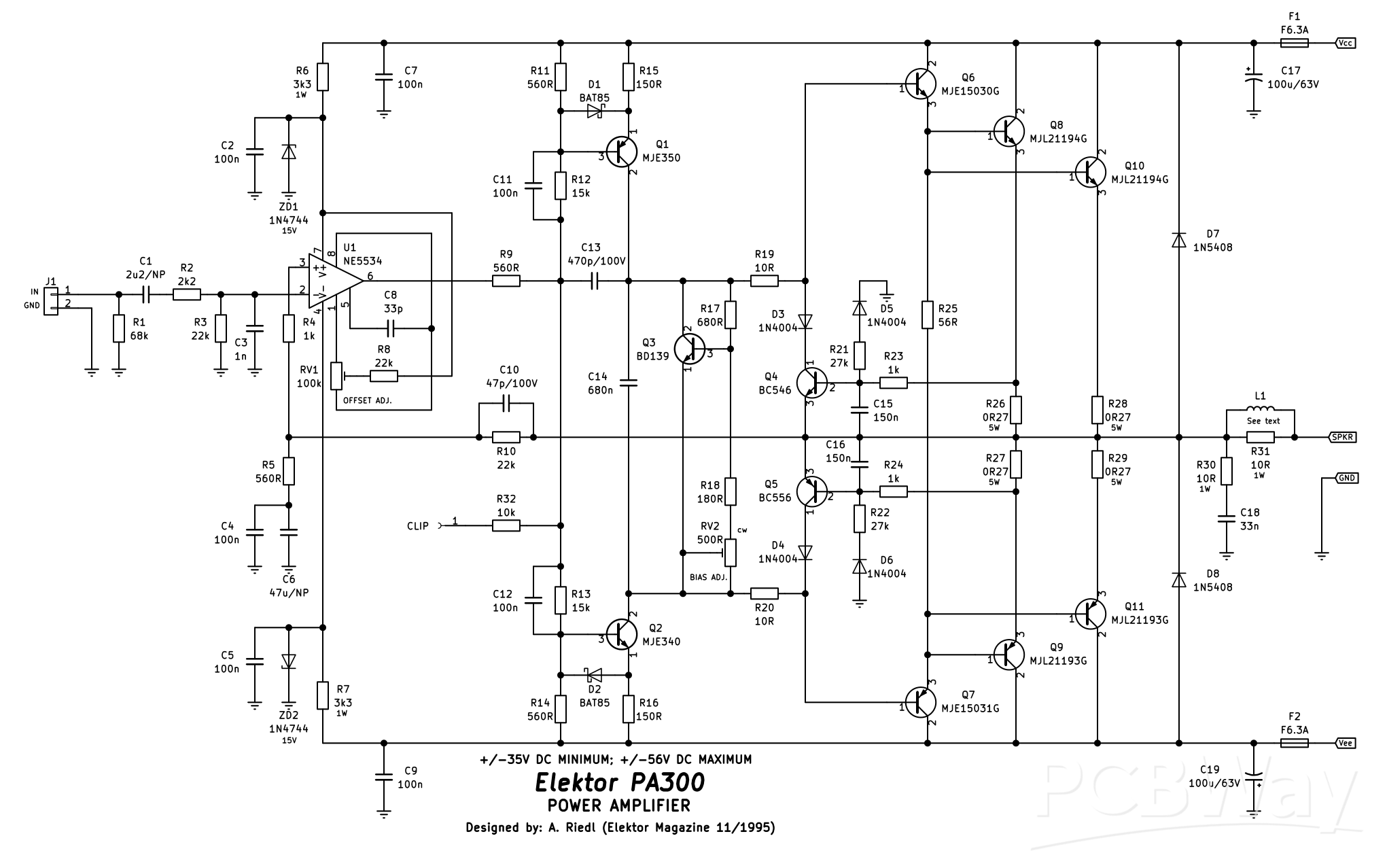
This power amplifier was originally designed by A. Riedl and published in the UK version of the “Elektor” magazine November 1995. Now, as a few of the parts are obsolete, and because the original used TO-3 output transistors; it has been redesigned with a new PCB, using modern commonly available parts and flat-pack output transistors. Featuring a wide operating voltage range (at the expense of power output), good thermal and overall stability and excellent frequency response; this amplifier can be used for virtually anything, from a powered subwoofer to a guitar amplifier.
For the power supply, there will be a separate PCB to go with this in the future (which will be linked here when available), which will include the protection circuitry. The voltage should not exceed +/-56V (112V) DC and the transformer should be a minimum of no less than 300VA. This is a transformer with two secondary windings of 40V AC and should be a toroidal one.
The most interesting aspect of this design is the use of an NE5534P operational amplifier U1. This is configured as a differential amplifier and is being used to replace the traditional long-tail pair input stage with current sources and mirrors. All of that stuff is internalised within the opamp, making the layout of the PCB simpler.
Specifications (+/-50VDC)
Input sensitivity: 1V RMS (pending update, I didn't re-measure this at the higher supply voltage)
Input impedance: 17.8k
Power output: 82.5W into 8 ohms, 111.3W into 4 ohms
Frequency response: 18Hz - 22Hz (@ 5.3W into 8 ohms)
THD: <0.05%
Stability: Unconditional
Construction
Begin construction by first mounting all the low profile 0.5W 1% metal film resistors. D1 and D2, the BAT85 Schottky diodes can also be installed along with D3 to D6, the 1N4004 rectifier diodes. If you wish to use an IC socket for U1 (optional), the NE5534P, you can install this next. If you choose not to use an IC socket, you can solder in U1 noting correct orientation. Next, install the PCB pin for the “CLIP” output (optional), along with the four M205 fuse clips for F1 and F2. Pay particular attention to the orientation of the fuse clips so that the “tang” faces out away from the physical fuse. The four 6.3mm male spade terminals can be soldered in next.
Now, R6, R7 and R30 can be installed next leaving an “air-gap” between the resistor body and the PCB. R31/L1 will be discussed later, so do not install that resistor at this point.
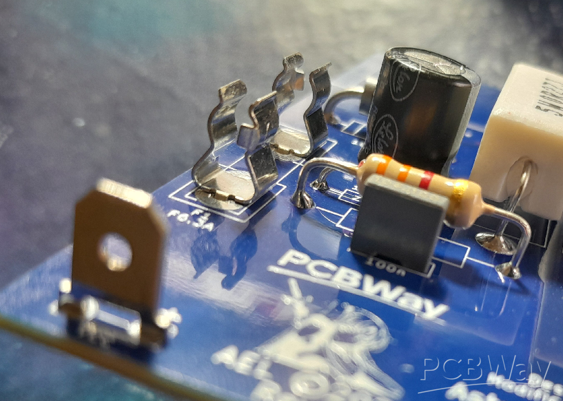
Fig. 1: Example of an “air-gap” of components that will disipate heat. Also, note the orientation of the fuse clips.
ZD1, ZD2 including D7 and D8 can be installed observing the same “air-gap”. Now, install all the ceramic and MKT capacitors in with just one caveat; C11 and C14 are marked as 100V on the schematic, but 250V in the bill of materials. I would suggest using the 250V rated capacitors if running at the full supply rails of +/-56V.
RV1 and RV2 can now be installed paying particular attention to the correct value in the correct place and also that RV2 is oriented with its adjustment screw pointing to the left of the PCB. Inserting it in the other way around will result in reverse operation of the trimpot, ie: fully anti-clockwise would be maximum bias! We don’t want this.
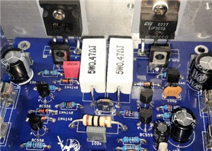
Install all the electrolytic capacitors next, paying attention to correct orientation of the polarized ones; the non-polarized ones (C1, C7) can be installed either way around. Q4 and Q5, the BC546 and BC556 respectively can be installed, along with the 0.27 ohm 5W resistors R26 to R29 making sure to give each of the four resistors an “air-gap”. That will complete this phase of construction, as we need to move on to winding L1.
Winding L1
L1 is wound around R31’s body, using around a 230mm length of 0.4mm diameter enamelled copper wire. Gently scrape the enamel coating off of one end of the wire with a hobby knife about 1cm (10mm) up the length of the wire. Fashion R31 by bending its leads at right angles so it will fit nicely in the PCB, then wrap the scraped end of the wire around one leg of the resistor near its body. Solder this in place, and it may take a bit of heat to solder properly if the enamel wasn’t quite removed properly. Wind 11 - 12 turns of the wire around the resistor’s body; winding direction isn’t important. Once you’ve reached the number of turns, trim the wire to around 1cm (10mm) of “hang-off”, and scrape this length of its enamel with the knife. Wrap the scraped portion around the remaining leg of the resistor and solder it in place. Once completed, you should have something similar to the below photo. It can now be soldered in to the PCB.

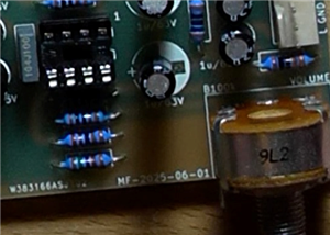
Fig. 2: Close-up showing completed L1/R31 combination soldered into the PCB.
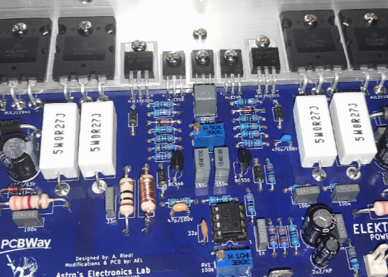
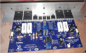
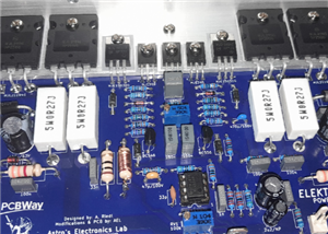
The below photo shows what you should have at this stage of construction (ignore the 47pF capacitor is missing, as I didn’t have one suitable at the time of taking the photo). Now, you need to turn your attention to drilling the heatsink bracket so that the output stage transistors can be soldered in to complete assembly.
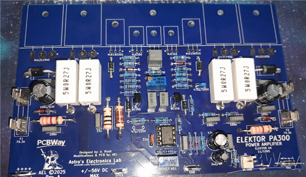
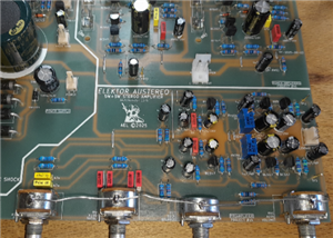
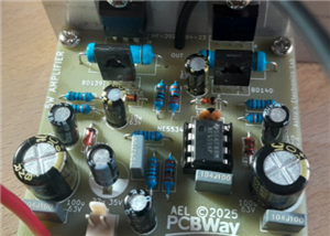
Fig. 3: Photo showing the completed assembly before moving on to assembling the output stage and heatsink bracket. The 47pF capacitor is only missing in this photo as I didn’t have one at the time.
Heatsink Bracket
Below is the drilling guide for the aluminium L-bracket with 3.5mm diameter holes. This needs to be done first before mounting the output transistors.
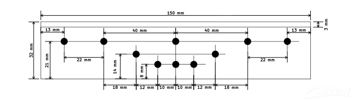
Fig. 4: Heatsink bracket drilling guide.
Once it is drilled, you should have something that looks like the below photo (note, mine is 200mm long).
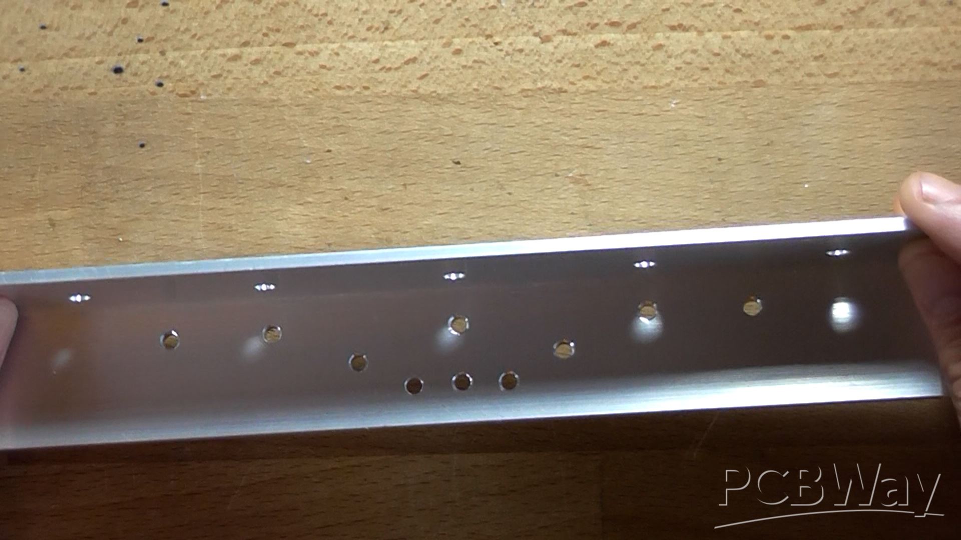
Fig. 5: Example of the drilled aluminium bracket. I will leave it up to you where to drill the mounting holes on the heatsink-face of the bracket. This is dependant on the type of heatsink and heatsink fin spacing.
Final Assembly
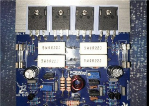
Now all the transistors that mount at the the top of the board can be installed with their legs bent at right-angles appropriately to fit in its place on the board with isolation kits (TO-3P for Q8 - Q11 and TO-220 for Q1 - Q3 and Q6 to Q7). Only the TO-220 transistors (Q6 and Q7) require the screw insulating bushing, the rest do not.
Fig. 6: Example of transistor isolation. 1) silicone-rubber SIL washer; 2) insulating bushing; 3a and b) M3 flat washers; 4) M3 nut; 5) M3 screw long enough to go through the bracket, PCB and accept all the hardware and 6) a shake-proof washer.
For the TO-126 devices (Q1 - Q3), I would advise trimming the insulation washers down by 5mm on the bottom and 2mm either side. This will make the final mounted transistors look neater without the ends of the washers overhanging each other.
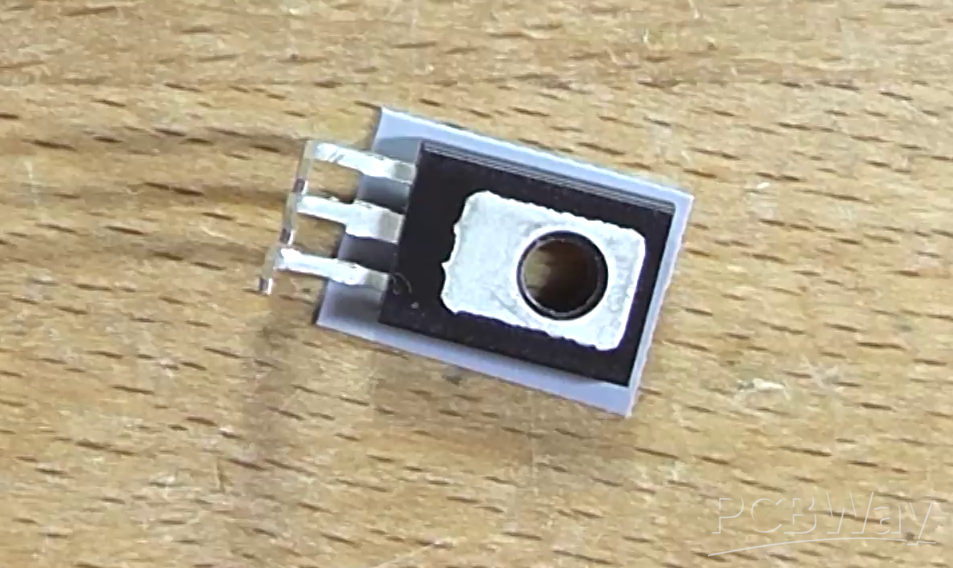
Fig. 7: Example of trimmed SIL washer. You can actually buy washers designed to fit TO-126 transistors, I just can’t get them easily in Australia.
Line the bracket holes up to the holes in the PCB. Temporarily install a screw and nut at one end of the bracket to secure it from sliding around and start mounting the transistors from the other end. Do not solder them in yet and don’t tighten the screws down until you get to the last transistor. Once all transistors are installed loosely, make sure all the isolation washers are straight and then you can begin gently tightening each transistor. Not too tight, you don’t want to crack the plastic casing of the relatively expensive output transistors! Just tight enough.
With a multimeter set to continuity, test each transistor is isolated from the bracket by touching one probe to the bracket and the other to each center lead of each transistor in turn. You shouldn't have a beep (or a reading close to 0 ohm if using an ordinary resistance test), it should be completely open-load. If you see a short, loosen and adjust the SIL washer until the short goes away; or replace the washer.
Now, finish it off by soldering them in and trimming off the excess lead lengths. If you installed an IC socket for U1, you can plug an NE5534P IC into the socket now (noting correct orientation). And that’s the construction complete! You can now turn it the correct way up and stare at for a few minutes, if you wish!
Testing
Before testing can begin, rotate RV2 (the bias pot) all the way fully anti-clockwise; this is maximum resistance, minimum bias. Never test any power amplifier without it attached to a suitable heatsink - ever. Even if you don’t have a heatsink drilled with the correct holes to mount the bracket properly, you can “get away with” g-clamping the bracket to the heatsink (you don’t need to go cranking the hell out of the g-clamps, either; just tight enough to hold the two together with no slipping).
Before applying any form of power, double-check your soldering work thoroughly making sure you don’t have solder-bridges between components or pins not soldered correctly, if at all. This will save a lot of headaches later.
If you have a dual-channel bench supply with current limiting, this is easier. Initially set the power supply to 15V on both channels with a current limit of 100mA. Install F1 and F2 and connect one supply’s positive to Vee, the negative to GND and the positive of the second supply to GND and its negative to Vee. Switch on and note the current draw. If the voltage drops right down and the supplies reach 100mA current limit, there’s a problem. Switch off and check for the error, faulty component, etc.. You should only see a current of around 7 to 9mA.
If you don’t have a dual-channel bench supply, this is harder, but not impossible. Connect up the power supply to the board and remove F1 and F2. Install two 100 ohm 5W “saftey resistors” across each fuse holder. This will limit the current if there’s a fault. Connect a volt meter across one of the resistors. Apply power and note the voltage reading across the resistor. If the voltage is greater than 4V (or close to the supply rail voltage), switch off immediately! If the resistors are hot, it’s drawing too much current. Check for the fault and correct it. Did you solder the bias pot the correct way around and is it at full anti-clockwise?
If you’re using the bench supply, switch off the power allowing time for capacitors to discharge and remove F1 and F2 fuses. Install two 100 ohm 5W “safety resistors” across each fuse holder (this will be used later to set the bias). Wind up the voltage to the voltage the amplifier will be running at (+/-56V maximum) or, if your supplies only go to 30V, this is also fine for initial testing.
Now connect a volt meter with the positive on the output and the negative on GND. Apply power and note the output voltage. It shouldn’t be any higher than a few millivolts. If you're using a bench supply, if the current is still around the 7 to 9mA mark, current limiting can be set to 2A of both supplies. Adjust RV1 in either direction until you achieve 0mV on the output (+/-2mV). If this adjusts fine, you can move on to setting the bias; if not, there’s a mistake with a component on the board, or even a faulty component which will have to be corrected. With brand-new quality components sourced from reputable suppliers, such as Digikey, the amplifier should work first time correctly out of the box.
Next, carefully connect the probes of the voltmeter across one of the 100 ohm resistors; polarity isn’t really important. Take note of the voltage reading across the resistor and if it’s in minus, this can be ignored as the probes are probably backwards. Slowly wind RV2 (the bias pot) clockwise until you see a voltage of around 4V (+/-1V). This equates to roughly 40mA of quiescent current. Let the amplifier sit and warm up for a few minutes and verify/adjust the bias again as necessary. Finally re-verify the output offset is still close to 0V. If it has passed these tests and adjustments, switch off, remove the safety resistors and reinstall the fuses. You can now connect a speaker and a music source and give the amplifier a listening test. Enjoy!
Link to YouTube video on assembling this amplifier:
Elektor PA300 300W Power Amplifier
*PCBWay community is a sharing platform. We are not responsible for any design issues and parameter issues (board thickness, surface finish, etc.) you choose.


Raspberry Pi 5 7 Inch Touch Screen IPS 1024x600 HD LCD HDMI-compatible Display for RPI 4B 3B+ OPI 5 AIDA64 PC Secondary Screen(Without Speaker)
BUY NOW


- Comments(1)
- Likes(9)
More by Astro's Electronics Lab
-
 AEL-2011 Power Supply Module
NOTE: THIS INVOLVES MAINS WIRING AND MAINS POTENTIAL. IF YOU ARE NOT CONFIDENT IN HANDLING MAINS WIR...
AEL-2011 Power Supply Module
NOTE: THIS INVOLVES MAINS WIRING AND MAINS POTENTIAL. IF YOU ARE NOT CONFIDENT IN HANDLING MAINS WIR...
-
 AEL-2011 50W Power Amplifier
IntroductionThis little amplifier module measuring 100mm by 100mm is capable of producing 50W into 8...
AEL-2011 50W Power Amplifier
IntroductionThis little amplifier module measuring 100mm by 100mm is capable of producing 50W into 8...
-
 Elektor PA300 300W Power Amplifier
NOTE: This is an intermediate project; DO NOT attempt this as your first project if you’re a novice....
Elektor PA300 300W Power Amplifier
NOTE: This is an intermediate project; DO NOT attempt this as your first project if you’re a novice....
-
 Simple 45W Discrete Power Amplifier
This simple amplifier is capable of producing up to 45W in to 8 ohms at the specified supply rails o...
Simple 45W Discrete Power Amplifier
This simple amplifier is capable of producing up to 45W in to 8 ohms at the specified supply rails o...
-
 555 Timer 12VDC Motor Speed Controller
Using a 555 timer and PWM (Pulse-Width Modulation), by varying its duty-cycle, we can vary the speed...
555 Timer 12VDC Motor Speed Controller
Using a 555 timer and PWM (Pulse-Width Modulation), by varying its duty-cycle, we can vary the speed...
-
 Headphone Adaptor for Power Amplifiers
Add a headphone socket to any existing stereo amplifier that doesn't have one. This L-pad attenuator...
Headphone Adaptor for Power Amplifiers
Add a headphone socket to any existing stereo amplifier that doesn't have one. This L-pad attenuator...
-
 Soft-Start Circuit for Toroidal Transformers
WARNING: This project is connected to mains line voltage during its entire operation. This project s...
Soft-Start Circuit for Toroidal Transformers
WARNING: This project is connected to mains line voltage during its entire operation. This project s...
-
 AEL-50B Simple 50W Power Amplifier
Need a simple power amplifier to drive a loudspeaker that doesn't require any messy set-ups to get g...
AEL-50B Simple 50W Power Amplifier
Need a simple power amplifier to drive a loudspeaker that doesn't require any messy set-ups to get g...
-
 150W Lateral MOSFET Power Amplifier
NOTE 1: This project is not intended for beginners. It is intended for someone with a medium underst...
150W Lateral MOSFET Power Amplifier
NOTE 1: This project is not intended for beginners. It is intended for someone with a medium underst...
-
 Elektor Austereo 5W Stereo Amplifier
IntroductionThis little stereo amplifier will happily produce 5W RMS per-channel into 8 ohms and fea...
Elektor Austereo 5W Stereo Amplifier
IntroductionThis little stereo amplifier will happily produce 5W RMS per-channel into 8 ohms and fea...
-
 Simple NE5532 Stereo Preamplifier
Need a simple stereo preamplifier for a set of power amplifiers? Here's the solution. Based on an NE...
Simple NE5532 Stereo Preamplifier
Need a simple stereo preamplifier for a set of power amplifiers? Here's the solution. Based on an NE...
-
 NE5534 5W Utility Power Amplifier PSU
This power supply was intended for the NE5534 power amplifier project:https://www.pcbway.com/project...
NE5534 5W Utility Power Amplifier PSU
This power supply was intended for the NE5534 power amplifier project:https://www.pcbway.com/project...
-
 LM386 Amplifier For Electret Microphone (Bullhorn)
This little circuit was originally designed to have an electret microphone insert connected at the i...
LM386 Amplifier For Electret Microphone (Bullhorn)
This little circuit was originally designed to have an electret microphone insert connected at the i...
-
 NE5534 5W Utility Power Amplifier
I needed a small amplifier to drive a pair of bookshelf speakers for testing other audio gear, such ...
NE5534 5W Utility Power Amplifier
I needed a small amplifier to drive a pair of bookshelf speakers for testing other audio gear, such ...
-
 Guitar Practice Amplifier (0.5W)
This little amplifier will happily drive a 4 - 8 ohm speaker to pretty loud levels, complete with ov...
Guitar Practice Amplifier (0.5W)
This little amplifier will happily drive a 4 - 8 ohm speaker to pretty loud levels, complete with ov...
-
 100mW Utility Amplifier
Need a small amplifier to amplify a radio front-end, or similar? This will do it! It produces up to ...
100mW Utility Amplifier
Need a small amplifier to amplify a radio front-end, or similar? This will do it! It produces up to ...
-
 Car Alarm Deterrent Flasher
We've all seen them; a bright red flashing light on someone's car's dash board to indicate there is ...
Car Alarm Deterrent Flasher
We've all seen them; a bright red flashing light on someone's car's dash board to indicate there is ...
-
 555 Timer Bi-Stable AC Mains Switch
WARNING: THIS CIRCUIT IS CONNECTED DIRECTLY TO THE MAINS SUPPLY AND CAN BE DANGEROUS. EXTREME CARE S...
555 Timer Bi-Stable AC Mains Switch
WARNING: THIS CIRCUIT IS CONNECTED DIRECTLY TO THE MAINS SUPPLY AND CAN BE DANGEROUS. EXTREME CARE S...
-
Programmable Mist Maker - XIAO / QT PY Extension
404 0 0 -
RadioHAT - Raspberry Pi radio development platform
316 0 1 -
-
-
-
-
ARPS-2 – Arduino-Compatible Robot Project Shield for Arduino UNO
2867 0 6 -
A Compact Charging Breakout Board For Waveshare ESP32-C3
3370 3 8 -
AI-driven LoRa & LLM-enabled Kiosk & Food Delivery System
3689 2 2


