


|
|
ArduinoNano |
x 1 | |
|
|
OLED Display |
x 1 |

|
arduino IDEArduino
|
DIY Transistor Tester | Build Your Own LCR Meter at Home with Arduino Nano
Are you fascinated by electronics and want to create your own tools for testing components? Building a DIY Transistor Tester and LCR Meter is a fantastic way to enhance your electronics lab! In this guide, we'll show you how to construct an LCR Meter using an Arduino Nano, complete with a detailed schematic and code. Let's dive into this exciting project.
Why Build a Transistor Tester and LCR Meter?
An LCR Meter measures inductance (L), capacitance (C), and resistance (R), making it an invaluable tool for diagnosing electronic components. A Transistor Tester expands its functionality by testing semiconductors like transistors, diodes, and MOSFETs. By building your own, you not only save money but also learn the principles behind these measurements.
Components Required
To build this project, you will need:
- Arduino Nano
- OLED Display (0.96-inch)
- Resistors: 680Ω, 470kΩ
- Capacitors: Various for testing
- Push Button
- Jump Wires
- PCB or Breadboard
- Power Source: USB or 9V battery with a DC jack
Circuit Diagram

Key Connections
- The OLED display is connected via I2C (SCL to A5, SDA to A4).
- The test probes are connected to designated analog pins on the Arduino Nano.
- Resistors and capacitors are integrated for measurement calibration and testing.
- Circuit Diagram Explanation
- OLED Display: This is connected to the I2C pins (A4 and A5) of the Arduino Nano for displaying the results.
- Test Pins: Three pins are used as test probes, connected to analog input pins A0, A1, and A2.
- Resistors and Capacitors: These components form a part of the measurement circuit for calibration and testing purposes.
- Push Button: Used to start the testing process by triggering the Arduino Nano.
How It Works
- This device works by applying a test signal to the component and measuring the response:
- Resistance: Voltage divider principle
- Capacitance: RC time constant measurement
- Inductance: Impedance measurement with known capacitance
- The Arduino processes these readings, calculates the values, and displays them on the OLED.
Arduino Code
The Arduino Nano is the brain of this tester. It runs a comprehensive codebase that measures the electronic parameters and displays the results.
Key Features of the Code:
Supports multiple display types: OLED, LCD, etc.
Handles auto-calibration for precise readings
Self-test mode for troubleshooting
Code Explanation
Display Initialization: The code initializes the OLED display to ensure it is ready to show results.
Self-Test Mode: Includes functionality to test the circuit for any errors before operation.
Measurement Functions:
- Resistance: Measures the voltage drop across known resistors to calculate resistance.
- Capacitance: Measures charge/discharge time to determine capacitance values.
- Inductance: Uses an LC circuit to calculate inductance based on frequency response.
- Result Display: Results are processed and displayed on the OLED in a user-friendly format.
- Power Management: Implements features to conserve power when the device is idle.
Step-by-Step Assembly Guide
- Prepare the Components: Gather all the required components and tools.
- Build the Circuit: Use the schematic to wire the components on a breadboard or PCB.
- Upload the Code: Load the provided code into the Arduino Nano using the Arduino IDE.
- Test the Device: Power up the circuit and test known components to verify accuracy.
Video Tutorial:
Applications
- Test resistors, capacitors, and inductors.
- Diagnose faulty semiconductors like transistors and diodes.
- Use it as a learning tool for electronics enthusiasts.
Troubleshooting Tips
- Double-check the wiring to avoid short circuits.
- Ensure the Arduino Nano is properly powered.
- Use fresh components for calibration and testing.
Conclusion
Creating a DIY Transistor Tester and LCR Meter is a rewarding project that equips you with a powerful tool for your electronics lab. By following this guide, you’ll not only have a working device but also a deeper understanding of electronics. Happy building!

DIY Transistor Tester | Build Your Own LCR Meter at Home with Arduino Nano
*PCBWay community is a sharing platform. We are not responsible for any design issues and parameter issues (board thickness, surface finish, etc.) you choose.


Raspberry Pi 5 7 Inch Touch Screen IPS 1024x600 HD LCD HDMI-compatible Display for RPI 4B 3B+ OPI 5 AIDA64 PC Secondary Screen(Without Speaker)
BUY NOW


- Comments(3)
- Likes(9)
- 1 USER VOTES
- YOUR VOTE 0.00 0.00

-
10design
-
10usability
-
10creativity
-
10content
 More by Estiak Khan
-
 ⚡ How to Make a DIY Spot Welding Machine at Home for 18650 Batteries | Full Circuit & Working
If you’re working on battery pack projects using 18650 lithium-ion cells, then you know how importan...
⚡ How to Make a DIY Spot Welding Machine at Home for 18650 Batteries | Full Circuit & Working
If you’re working on battery pack projects using 18650 lithium-ion cells, then you know how importan...
-
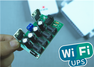 🔋 How to Make a Simple DIY Wi-Fi Router UPS at Home | Step-by-Step Guide with Circuit & PCB
Do you lose internet connection every time the power goes out?If yes, then this simple DIY Wi-Fi Rou...
🔋 How to Make a Simple DIY Wi-Fi Router UPS at Home | Step-by-Step Guide with Circuit & PCB
Do you lose internet connection every time the power goes out?If yes, then this simple DIY Wi-Fi Rou...
-
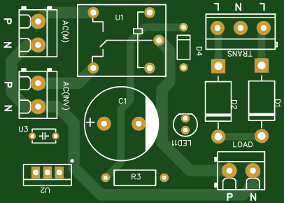 Automatic AC Changeover for Inverter
 – DIY Circuit GuideAre you tired of manually switching between ...
Automatic AC Changeover for Inverter
Automatic AC Changeover for Inverter – DIY Circuit GuideAre you tired of manually switching between ...
-
 How to Make a 12V AC/DC Fan Controller Module
If you're looking for an efficient way to control a 12V fan using either AC or DC input, this DIY pr...
How to Make a 12V AC/DC Fan Controller Module
If you're looking for an efficient way to control a 12V fan using either AC or DC input, this DIY pr...
-
 Autocut DC Mini IPS for DC 12V Load
If you are looking for a reliable Autocut DC Mini IPS for DC 12V ...
Autocut DC Mini IPS for DC 12V Load
Autocut DC Mini IPS for DC 12V LoadIf you are looking for a reliable Autocut DC Mini IPS for DC 12V ...
-
 Build a 12V Battery Autocut System with LCD Display
Are you looking for an efficient and affordable way to protect and monitor your 12V battery system? ...
Build a 12V Battery Autocut System with LCD Display
Are you looking for an efficient and affordable way to protect and monitor your 12V battery system? ...
-
 DIY Transistor Tester | Build Your Own LCR Meter at Home with Arduino Nano
Are you fascinated by electronics and want to create your own tools for testing components? Building...
DIY Transistor Tester | Build Your Own LCR Meter at Home with Arduino Nano
Are you fascinated by electronics and want to create your own tools for testing components? Building...
-
 How to Make a Pure Sine Wave Inverter Using EG8010 + IR2110S | Step-by-Step Guide
If you are looking ...
How to Make a Pure Sine Wave Inverter Using EG8010 + IR2110S | Step-by-Step Guide
How to Make a Pure Sine Wave Inverter Using EG8010 + IR2110S | Step-by-Step GuideIf you are looking ...
-
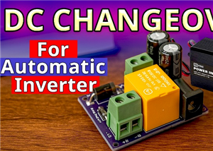 🔋 How to Make DC Changeover for Automatic Inverter System | DIY Inverter Changeover Switch
Are you tired of manually switching between DC power supply and battery backup during load shedding?...
🔋 How to Make DC Changeover for Automatic Inverter System | DIY Inverter Changeover Switch
Are you tired of manually switching between DC power supply and battery backup during load shedding?...
-
 No Need Adapter 🤔 WiFi Router UPS Making with Transformer
No Need Adapter WiFi Router UPS Making with Transformer | Complete Circuit DiagramAre you tired of ...
No Need Adapter 🤔 WiFi Router UPS Making with Transformer
No Need Adapter WiFi Router UPS Making with Transformer | Complete Circuit DiagramAre you tired of ...
-
 🔋 How to Make a Power Bank Module at Home
Are you looking to build your own DIY power bank at home? In this blog post, we’ll show you how to c...
🔋 How to Make a Power Bank Module at Home
Are you looking to build your own DIY power bank at home? In this blog post, we’ll show you how to c...
-
 Cute LIT 220W Inverter Load Test ⚡ Auto Changeover IPS System Explained! 🔋 Real Load Backup Test
Are you looking for a reliable backup power solution for your WiFi router, CCTV, or small appliances...
Cute LIT 220W Inverter Load Test ⚡ Auto Changeover IPS System Explained! 🔋 Real Load Backup Test
Are you looking for a reliable backup power solution for your WiFi router, CCTV, or small appliances...
-
 ⚡ Hybrid WiFi Router UPS for Solar System
IntroductionPower cuts in off-grid areas can disrupt internet connectivity. With the rise of solar s...
⚡ Hybrid WiFi Router UPS for Solar System
IntroductionPower cuts in off-grid areas can disrupt internet connectivity. With the rise of solar s...
-
 🔋 DIY Solar-Based Mini IPS at Home | Auto Load Changeover Circuit for 12V DC Fan/Light
If you're looking for an easy and affordable solution to keep your 12V DC fan or light running even ...
🔋 DIY Solar-Based Mini IPS at Home | Auto Load Changeover Circuit for 12V DC Fan/Light
If you're looking for an easy and affordable solution to keep your 12V DC fan or light running even ...
-
 🔋 DIY Automatic Cut Off 12V Trickle Charger | Lead Acid Battery AutoCut Charger
Do you often charge your 12V lead-acid battery manually and worry about overcharging? With this DIY ...
🔋 DIY Automatic Cut Off 12V Trickle Charger | Lead Acid Battery AutoCut Charger
Do you often charge your 12V lead-acid battery manually and worry about overcharging? With this DIY ...
-
 🔥 DIY Smart 12V Battery at Home | Using 18650 Cells + Smart BMS
Looking for a way to build a powerful and smart 12V battery at home? In this guide, I'll show you h...
🔥 DIY Smart 12V Battery at Home | Using 18650 Cells + Smart BMS
Looking for a way to build a powerful and smart 12V battery at home? In this guide, I'll show you h...
-
 🎮 DIY Arduino Nano Snake Game Console with OLED Display
DIY Arduino Nano Snake Game Console with OLED Display and ButtonsDo you love retro games? Want to bu...
🎮 DIY Arduino Nano Snake Game Console with OLED Display
DIY Arduino Nano Snake Game Console with OLED Display and ButtonsDo you love retro games? Want to bu...
-
 DIY 150W IPS Making At Home with Auto Changeover System | Mini IPS 2025
How to Make an Automatic 150W IPS Using Two Circuit ModulesAre you looking for a reliable and effici...
DIY 150W IPS Making At Home with Auto Changeover System | Mini IPS 2025
How to Make an Automatic 150W IPS Using Two Circuit ModulesAre you looking for a reliable and effici...
-
-
ARPS-2 – Arduino-Compatible Robot Project Shield for Arduino UNO
2471 0 5 -
A Compact Charging Breakout Board For Waveshare ESP32-C3
2918 3 8 -
AI-driven LoRa & LLM-enabled Kiosk & Food Delivery System
3126 2 1 -
-
-
-
ESP32-C3 BLE Keyboard - Battery Powered with USB-C Charging
3184 0 2


