


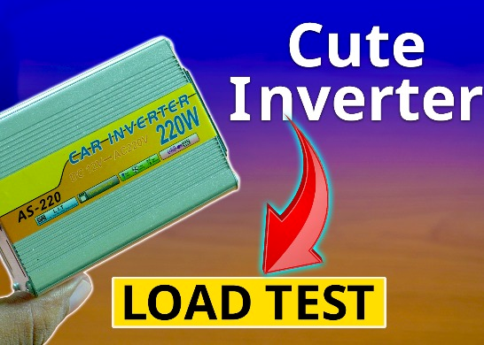
Cute LIT 220W Inverter Load Test ⚡ Auto Changeover IPS System Explained! 🔋 Real Load Backup Test
Are you looking for a reliable backup power solution for your WiFi router, CCTV, or small appliances? In this detailed post, we’ll explore how to test a Cute LIT 220W inverter with an Auto Load/Off Changeover Circuit, ensuring smooth and automatic power backup with zero downtime.
This guide is powered by a real schematic (see image below) that was tested with actual loads like LED bulbs, routers, and small fans to measure performance and battery efficiency.
✅ What You’ll Learn:
- How to build and test a 220W inverter system
- Working principle of auto-changeover IPS circuits
- Circuit diagram analysis
- Real load testing & performance results
- LED power indicators & backup time estimation
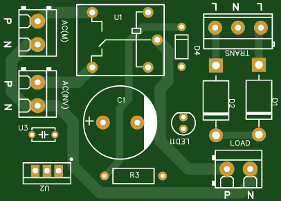
📷 Circuit Diagram:
Below is the schematic diagram used for the test. Designed using EasyEDA:

⚙️ Circuit Diagram Explanation:
This circuit is a Mini DC IPS Auto Load/Off Changeover System, designed to switch between the main DC input and a 12V battery when the main power fails.
🧩 Key Sections:
🔌 Input Power Section:
Power Socket (IN): Receives 12V DC from an adapter or solar system.
PWR1 + LED2: A 1K resistor with a red LED (LED2) indicates when input power is present.
⚡ Relay Section:
Relay (SRD-05VDC-SL-C): A 5V coil relay used to switch between power sources.
Relay Pins:
Pin 2 & 5: Connected to DC input (activates coil)
Pin 3 (COM): Connected to load output
Pin 4: Ground
D1 (1N4007): Flyback diode across the relay coil to prevent voltage spikes.
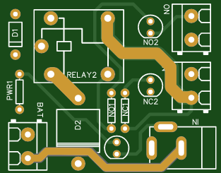
🔋 Battery Section:
BAT Connector: Connected to a 12V DC lead-acid or Li-ion battery.
When the relay is not energized (power off), the load connects to the battery via NC (Normally Closed) pin.
🔁 Auto Load Switch Logic:
NO Connector: Connected to DC input — powers the load when relay is ON.
NC Connector: Connected to battery — powers the load when relay is OFF.
NC1/NO1 + LEDs: Status LEDs to indicate which source is currently supplying power.
🔦 LED Indicators:
NC1 + NC2: Red LEDs indicate when load is running on the battery.
NO1 + NO2: Red LEDs indicate when load is running on the main power.
🔧 Circuit Components (as per schematic):
Relay: SRD-05VDC-SL-C
Diodes: 1N4007, 6A10
Resistors: 1K Ohm (x3)
LEDs: 5mm Red (x3)
Power Socket: DC input
Battery Connector: 12V DC (Typical)
NC/NO Terminals: Output connections
GND: Common ground line
🧠 How It Works:
When AC mains (via adapter) is ON, the relay activates and powers the load directly.
When mains fail, the relay deactivates, switching the load to the battery.
The LED indicators show active power source.
Diodes protect the relay and ensure reverse current protection.
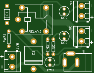
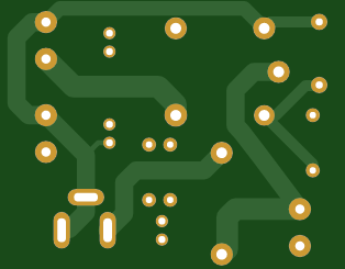
📷 Schematic Overview:
Below is the tested circuit diagram for the mini auto-load/off IPS system used in this test:
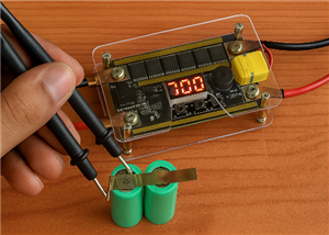
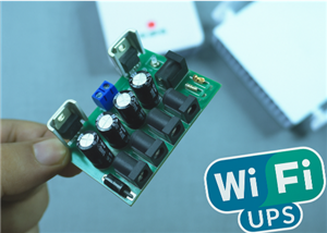
🔍 Real Load Test with Cute LIT 220W Inverter:
We tested the system with:
💡 12V 10W LED Bulb
🌐 WiFi Router (5V via buck converter)
🌀 Mini DC Fan
🔌 USB mobile charger
Total load: ~45W
Backup Time: 2.5+ hours on a 12V 7.5Ah Battery
YouTube Video:
📊 Final Thoughts:
If you want a low-cost DIY UPS or IPS system, this auto changeover circuit is a must-have. It ensures your devices stay online without manual switching. Combined with the Cute LIT 220W inverter, this becomes a powerful mini-IPS system that you can rely on during power cuts.
Cute LIT 220W Inverter Load Test ⚡ Auto Changeover IPS System Explained! 🔋 Real Load Backup Test
*Due to unresolved design issues with this PCB, orders cannot be placed at this time. We appreciate your understanding.


Raspberry Pi 5 7 Inch Touch Screen IPS 1024x600 HD LCD HDMI-compatible Display for RPI 4B 3B+ OPI 5 AIDA64 PC Secondary Screen(Without Speaker)
BUY NOW


- Comments(0)
- Likes(1)
 More by Estiak Khan
-
 ⚡ How to Make a DIY Spot Welding Machine at Home for 18650 Batteries | Full Circuit & Working
If you’re working on battery pack projects using 18650 lithium-ion cells, then you know how importan...
⚡ How to Make a DIY Spot Welding Machine at Home for 18650 Batteries | Full Circuit & Working
If you’re working on battery pack projects using 18650 lithium-ion cells, then you know how importan...
-
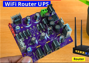
 🔋 How to Make a Simple DIY Wi-Fi Router UPS at Home | Step-by-Step Guide with Circuit & PCB
Do you lose internet connection every time the power goes out?If yes, then this simple DIY Wi-Fi Rou...
🔋 How to Make a Simple DIY Wi-Fi Router UPS at Home | Step-by-Step Guide with Circuit & PCB
Do you lose internet connection every time the power goes out?If yes, then this simple DIY Wi-Fi Rou...
-
 Automatic AC Changeover for Inverter
 – DIY Circuit GuideAre you tired of manually switching between ...
Automatic AC Changeover for Inverter
Automatic AC Changeover for Inverter – DIY Circuit GuideAre you tired of manually switching between ...
-
 How to Make a 12V AC/DC Fan Controller Module
If you're looking for an efficient way to control a 12V fan using either AC or DC input, this DIY pr...
How to Make a 12V AC/DC Fan Controller Module
If you're looking for an efficient way to control a 12V fan using either AC or DC input, this DIY pr...
-
 Autocut DC Mini IPS for DC 12V Load
If you are looking for a reliable Autocut DC Mini IPS for DC 12V ...
Autocut DC Mini IPS for DC 12V Load
Autocut DC Mini IPS for DC 12V LoadIf you are looking for a reliable Autocut DC Mini IPS for DC 12V ...
-
 Build a 12V Battery Autocut System with LCD Display
Are you looking for an efficient and affordable way to protect and monitor your 12V battery system? ...
Build a 12V Battery Autocut System with LCD Display
Are you looking for an efficient and affordable way to protect and monitor your 12V battery system? ...
-
 DIY Transistor Tester | Build Your Own LCR Meter at Home with Arduino Nano
Are you fascinated by electronics and want to create your own tools for testing components? Building...
DIY Transistor Tester | Build Your Own LCR Meter at Home with Arduino Nano
Are you fascinated by electronics and want to create your own tools for testing components? Building...
-
 How to Make a Pure Sine Wave Inverter Using EG8010 + IR2110S | Step-by-Step Guide
If you are looking ...
How to Make a Pure Sine Wave Inverter Using EG8010 + IR2110S | Step-by-Step Guide
How to Make a Pure Sine Wave Inverter Using EG8010 + IR2110S | Step-by-Step GuideIf you are looking ...
-
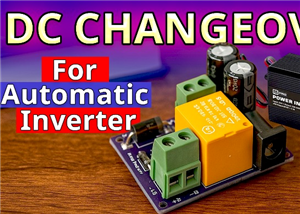 🔋 How to Make DC Changeover for Automatic Inverter System | DIY Inverter Changeover Switch
Are you tired of manually switching between DC power supply and battery backup during load shedding?...
🔋 How to Make DC Changeover for Automatic Inverter System | DIY Inverter Changeover Switch
Are you tired of manually switching between DC power supply and battery backup during load shedding?...
-
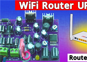 No Need Adapter 🤔 WiFi Router UPS Making with Transformer
No Need Adapter WiFi Router UPS Making with Transformer | Complete Circuit DiagramAre you tired of ...
No Need Adapter 🤔 WiFi Router UPS Making with Transformer
No Need Adapter WiFi Router UPS Making with Transformer | Complete Circuit DiagramAre you tired of ...
-
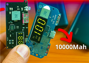 🔋 How to Make a Power Bank Module at Home
Are you looking to build your own DIY power bank at home? In this blog post, we’ll show you how to c...
🔋 How to Make a Power Bank Module at Home
Are you looking to build your own DIY power bank at home? In this blog post, we’ll show you how to c...
-
 Cute LIT 220W Inverter Load Test ⚡ Auto Changeover IPS System Explained! 🔋 Real Load Backup Test
Are you looking for a reliable backup power solution for your WiFi router, CCTV, or small appliances...
Cute LIT 220W Inverter Load Test ⚡ Auto Changeover IPS System Explained! 🔋 Real Load Backup Test
Are you looking for a reliable backup power solution for your WiFi router, CCTV, or small appliances...
-
 ⚡ Hybrid WiFi Router UPS for Solar System
IntroductionPower cuts in off-grid areas can disrupt internet connectivity. With the rise of solar s...
⚡ Hybrid WiFi Router UPS for Solar System
IntroductionPower cuts in off-grid areas can disrupt internet connectivity. With the rise of solar s...
-
 🔋 DIY Solar-Based Mini IPS at Home | Auto Load Changeover Circuit for 12V DC Fan/Light
If you're looking for an easy and affordable solution to keep your 12V DC fan or light running even ...
🔋 DIY Solar-Based Mini IPS at Home | Auto Load Changeover Circuit for 12V DC Fan/Light
If you're looking for an easy and affordable solution to keep your 12V DC fan or light running even ...
-
 🔋 DIY Automatic Cut Off 12V Trickle Charger | Lead Acid Battery AutoCut Charger
Do you often charge your 12V lead-acid battery manually and worry about overcharging? With this DIY ...
🔋 DIY Automatic Cut Off 12V Trickle Charger | Lead Acid Battery AutoCut Charger
Do you often charge your 12V lead-acid battery manually and worry about overcharging? With this DIY ...
-
 🔥 DIY Smart 12V Battery at Home | Using 18650 Cells + Smart BMS
Looking for a way to build a powerful and smart 12V battery at home? In this guide, I'll show you h...
🔥 DIY Smart 12V Battery at Home | Using 18650 Cells + Smart BMS
Looking for a way to build a powerful and smart 12V battery at home? In this guide, I'll show you h...
-
 🎮 DIY Arduino Nano Snake Game Console with OLED Display
DIY Arduino Nano Snake Game Console with OLED Display and ButtonsDo you love retro games? Want to bu...
🎮 DIY Arduino Nano Snake Game Console with OLED Display
DIY Arduino Nano Snake Game Console with OLED Display and ButtonsDo you love retro games? Want to bu...
-
 DIY 150W IPS Making At Home with Auto Changeover System | Mini IPS 2025
How to Make an Automatic 150W IPS Using Two Circuit ModulesAre you looking for a reliable and effici...
DIY 150W IPS Making At Home with Auto Changeover System | Mini IPS 2025
How to Make an Automatic 150W IPS Using Two Circuit ModulesAre you looking for a reliable and effici...
-
-
ARPS-2 – Arduino-Compatible Robot Project Shield for Arduino UNO
1668 0 5 -
A Compact Charging Breakout Board For Waveshare ESP32-C3
2205 3 7 -
AI-driven LoRa & LLM-enabled Kiosk & Food Delivery System
2231 2 0 -
-
-
-
ESP32-C3 BLE Keyboard - Battery Powered with USB-C Charging
2387 0 2 -


