


How to Make a Pure Sine Wave Inverter Using EG8010 + IR2110S | Step-by-Step Guide
How to Make a Pure Sine Wave Inverter Using EG8010 + IR2110S | Step-by-Step Guide
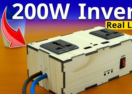
If you are looking for a reliable way to make your own inverter at home, this guide will help you build a low-frequency pure sine wave inverter using the EG8010 ASIC SPWM controller, IR2110S driver ICs, and MOSFETs. This design is widely used for 220V AC output inverters suitable for home appliances, fans, lights, computers, and more.

In this post, we will explain the circuit diagram, working principle, PCB conversion, and connections so you can easily make your own inverter.
🔧 Components Required
EG8010 – SPWM Controller IC
IR2110S – High/Low side MOSFET driver IC
MOSFETs (IRF3205 / RFP260N / similar) – Power switching
LM393 – Comparator for protection
7805 Regulator – For 5V supply
NTC Thermistor – Temperature sensing for cooling fan
Power Transformer (12V to 220V) – Step-up transformer
Diodes (FR107 / IN4148) – Fast recovery and switching
Capacitors (10µF, 100µF, 4.7µF, etc.) – Filtering
Resistors (4.7Ω, 100k, etc.) – Gate & bias resistors
Cooling Fan – Automatic temperature control
⚡ Circuit Diagram Explanation
.png)
- The above circuit is based on the EG8010 + IR2110S Sinusoidal Inverter Design.
- SPWM Generation
- The EG8010 IC generates pure sine wave PWM signals.
- These signals are sent to the IR2110S driver ICs which amplify them to drive the MOSFET gates.
- MOSFET Full-Bridge
- Four MOSFETs (Q1–Q4) form an H-Bridge.
- The SPWM signals switch these MOSFETs alternately to produce AC at the transformer input.
- Step-Up Transformer
- The transformer converts 12V DC to 220V AC output.
- Since it’s low frequency, it is highly efficient for household loads.
- Cooling and Protection
- An NTC temperature sensor automatically controls the fan.
- The LM393 comparator monitors feedback and protects against over-current.
📐 How the Inverter Works

When 12V DC is applied, the EG8010 controller generates a sinusoidal PWM signal.
The IR2110S driver amplifies the signals and drives the MOSFETs.
The MOSFETs alternately pass current through the transformer primary, creating an AC waveform.
At the secondary, you get 220V pure sine wave output suitable for home use.
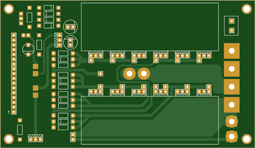
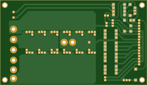
🖥️ Converting Circuit into PCB

To make this project more professional:
Draw the circuit in PCB design software (EasyEDA, KiCad, Altium).
Use thick copper traces for the MOSFET and transformer lines (high current path).
Keep gate driver traces short for better switching.
Add heat sinks for MOSFETs and ensure good ventilation.
You can easily order the PCB from manufacturers like PCBWay.
🔌 Practical Connection Guide
Battery Input: Connect 12V battery to +12V and GND.
AC Output: Connect the transformer secondary to the output terminals for 220V AC.
Cooling Fan: Connect to the thermistor-controlled output for auto ON/OFF.
Load: Plug in fan, lights, or other appliances (up to design rating).
Video Reference:
✅ Advantages of This Design
Pure sine wave output (safe for sensitive electronics)
Low frequency transformer – reliable & durable
Automatic cooling fan control
High efficiency with MOSFET H-Bridge
Easy PCB conversion for compact design
🏆 Conclusion
With the EG8010 + IR2110S based pure sine wave inverter, you can easily design a reliable and efficient power backup system. This inverter provides stable 220V AC output, making it perfect for home appliances, computers, and other electronics. By converting the schematic into a PCB, you can make your own professional inverter for long-term use.
How to Make a Pure Sine Wave Inverter Using EG8010 + IR2110S | Step-by-Step Guide
*PCBWay community is a sharing platform. We are not responsible for any design issues and parameter issues (board thickness, surface finish, etc.) you choose.


Raspberry Pi 5 7 Inch Touch Screen IPS 1024x600 HD LCD HDMI-compatible Display for RPI 4B 3B+ OPI 5 AIDA64 PC Secondary Screen(Without Speaker)
BUY NOW


- Comments(1)
- Likes(0)
 More by Estiak Khan
-
 ⚡ How to Make a DIY Spot Welding Machine at Home for 18650 Batteries | Full Circuit & Working
If you’re working on battery pack projects using 18650 lithium-ion cells, then you know how importan...
⚡ How to Make a DIY Spot Welding Machine at Home for 18650 Batteries | Full Circuit & Working
If you’re working on battery pack projects using 18650 lithium-ion cells, then you know how importan...
-
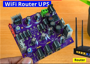
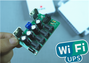 🔋 How to Make a Simple DIY Wi-Fi Router UPS at Home | Step-by-Step Guide with Circuit & PCB
Do you lose internet connection every time the power goes out?If yes, then this simple DIY Wi-Fi Rou...
🔋 How to Make a Simple DIY Wi-Fi Router UPS at Home | Step-by-Step Guide with Circuit & PCB
Do you lose internet connection every time the power goes out?If yes, then this simple DIY Wi-Fi Rou...
-
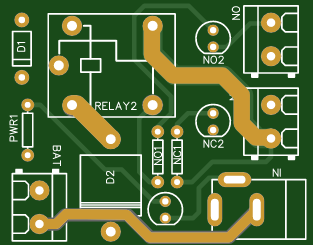
 Automatic AC Changeover for Inverter
 – DIY Circuit GuideAre you tired of manually switching between ...
Automatic AC Changeover for Inverter
Automatic AC Changeover for Inverter – DIY Circuit GuideAre you tired of manually switching between ...
-
 How to Make a 12V AC/DC Fan Controller Module
If you're looking for an efficient way to control a 12V fan using either AC or DC input, this DIY pr...
How to Make a 12V AC/DC Fan Controller Module
If you're looking for an efficient way to control a 12V fan using either AC or DC input, this DIY pr...
-
 Autocut DC Mini IPS for DC 12V Load
If you are looking for a reliable Autocut DC Mini IPS for DC 12V ...
Autocut DC Mini IPS for DC 12V Load
Autocut DC Mini IPS for DC 12V LoadIf you are looking for a reliable Autocut DC Mini IPS for DC 12V ...
-
 Build a 12V Battery Autocut System with LCD Display
Are you looking for an efficient and affordable way to protect and monitor your 12V battery system? ...
Build a 12V Battery Autocut System with LCD Display
Are you looking for an efficient and affordable way to protect and monitor your 12V battery system? ...
-
 DIY Transistor Tester | Build Your Own LCR Meter at Home with Arduino Nano
Are you fascinated by electronics and want to create your own tools for testing components? Building...
DIY Transistor Tester | Build Your Own LCR Meter at Home with Arduino Nano
Are you fascinated by electronics and want to create your own tools for testing components? Building...
-
 How to Make a Pure Sine Wave Inverter Using EG8010 + IR2110S | Step-by-Step Guide
If you are looking ...
How to Make a Pure Sine Wave Inverter Using EG8010 + IR2110S | Step-by-Step Guide
How to Make a Pure Sine Wave Inverter Using EG8010 + IR2110S | Step-by-Step GuideIf you are looking ...
-
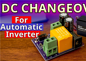 🔋 How to Make DC Changeover for Automatic Inverter System | DIY Inverter Changeover Switch
Are you tired of manually switching between DC power supply and battery backup during load shedding?...
🔋 How to Make DC Changeover for Automatic Inverter System | DIY Inverter Changeover Switch
Are you tired of manually switching between DC power supply and battery backup during load shedding?...
-
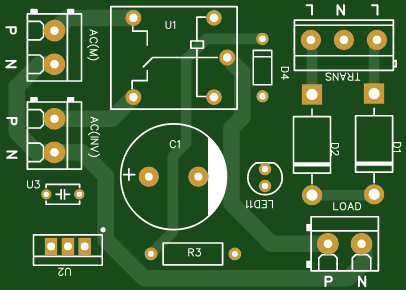
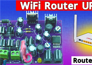 No Need Adapter 🤔 WiFi Router UPS Making with Transformer
No Need Adapter WiFi Router UPS Making with Transformer | Complete Circuit DiagramAre you tired of ...
No Need Adapter 🤔 WiFi Router UPS Making with Transformer
No Need Adapter WiFi Router UPS Making with Transformer | Complete Circuit DiagramAre you tired of ...
-
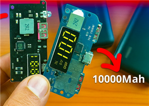 🔋 How to Make a Power Bank Module at Home
Are you looking to build your own DIY power bank at home? In this blog post, we’ll show you how to c...
🔋 How to Make a Power Bank Module at Home
Are you looking to build your own DIY power bank at home? In this blog post, we’ll show you how to c...
-
 Cute LIT 220W Inverter Load Test ⚡ Auto Changeover IPS System Explained! 🔋 Real Load Backup Test
Are you looking for a reliable backup power solution for your WiFi router, CCTV, or small appliances...
Cute LIT 220W Inverter Load Test ⚡ Auto Changeover IPS System Explained! 🔋 Real Load Backup Test
Are you looking for a reliable backup power solution for your WiFi router, CCTV, or small appliances...
-
 ⚡ Hybrid WiFi Router UPS for Solar System
IntroductionPower cuts in off-grid areas can disrupt internet connectivity. With the rise of solar s...
⚡ Hybrid WiFi Router UPS for Solar System
IntroductionPower cuts in off-grid areas can disrupt internet connectivity. With the rise of solar s...
-
 🔋 DIY Solar-Based Mini IPS at Home | Auto Load Changeover Circuit for 12V DC Fan/Light
If you're looking for an easy and affordable solution to keep your 12V DC fan or light running even ...
🔋 DIY Solar-Based Mini IPS at Home | Auto Load Changeover Circuit for 12V DC Fan/Light
If you're looking for an easy and affordable solution to keep your 12V DC fan or light running even ...
-
 🔋 DIY Automatic Cut Off 12V Trickle Charger | Lead Acid Battery AutoCut Charger
Do you often charge your 12V lead-acid battery manually and worry about overcharging? With this DIY ...
🔋 DIY Automatic Cut Off 12V Trickle Charger | Lead Acid Battery AutoCut Charger
Do you often charge your 12V lead-acid battery manually and worry about overcharging? With this DIY ...
-
 🔥 DIY Smart 12V Battery at Home | Using 18650 Cells + Smart BMS
Looking for a way to build a powerful and smart 12V battery at home? In this guide, I'll show you h...
🔥 DIY Smart 12V Battery at Home | Using 18650 Cells + Smart BMS
Looking for a way to build a powerful and smart 12V battery at home? In this guide, I'll show you h...
-
 🎮 DIY Arduino Nano Snake Game Console with OLED Display
DIY Arduino Nano Snake Game Console with OLED Display and ButtonsDo you love retro games? Want to bu...
🎮 DIY Arduino Nano Snake Game Console with OLED Display
DIY Arduino Nano Snake Game Console with OLED Display and ButtonsDo you love retro games? Want to bu...
-
 DIY 150W IPS Making At Home with Auto Changeover System | Mini IPS 2025
How to Make an Automatic 150W IPS Using Two Circuit ModulesAre you looking for a reliable and effici...
DIY 150W IPS Making At Home with Auto Changeover System | Mini IPS 2025
How to Make an Automatic 150W IPS Using Two Circuit ModulesAre you looking for a reliable and effici...
-
-
-
-
ARPS-2 – Arduino-Compatible Robot Project Shield for Arduino UNO
2626 0 5 -
A Compact Charging Breakout Board For Waveshare ESP32-C3
3102 3 8 -
AI-driven LoRa & LLM-enabled Kiosk & Food Delivery System
3327 2 1 -
-
-


