


|
|
ATMEGA328-PU |
x 1 | |
|
|
LCD 16,2 |
x 1 | |
|
|
DC_RELAY |
x 1 |
Build a 12V Battery Autocut System with LCD Display
Are you looking for an efficient and affordable way to protect and monitor your 12V battery system? In this tutorial, we will guide you through the process of creating a 12V Battery Autocut System with an LCD display for monitoring. This project is ideal for DIY enthusiasts and makers who want to control charging and discharging cycles automatically.
Below, we'll cover the complete circuit design, list of components, and code required for this project. The design is based on the ATmega328P microcontroller and features a 16x2 LCD for easy status updates.
.jpg)
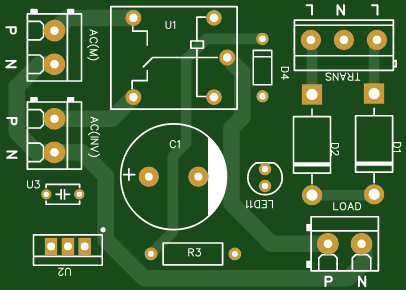
Circuit Diagram
The circuit diagram provides a clear layout of how components should be connected. You can view it in the image provided above. Below is a description of the key elements:

Key Components
- ATmega328P: Acts as the brain of the system, handling voltage sensing and relay control.
- 16x2 LCD Display: Displays the current battery voltage, charging status, and load status.
- Relays: Controls the connection of the load and charger to the battery.
- Voltage Divider (10kΩ and 5.6kΩ): Reduces the battery voltage to a level suitable for ADC input.
- Buttons: Used for manual full-cut and low-cut settings.
- Diodes (1N4007/1N5408): Prevent reverse current and protect the circuit.
- BC547 Transistors: Drives the relays.
Pin Configuration
LCD Pins:
RS: Pin 4
E: Pin 3
D4-D7: Pins 5-8
Relays:Load Relay: Pin 13
Charge Relay: Pin 12
Voltage Sensing:
Analog Pin A0
Ensure proper connections as shown in the schematic diagram to avoid errors.
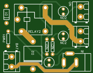
PCB Design & Order from PCBWay.com
To make your project more professional and reliable, designing a PCB is a great choice. With PCBWay.com, you can easily create and order your custom PCB for this project. Here’s how:
Design Your PCB:
Use software like EasyEDA or KiCAD to create the PCB layout based on the schematic.
Ensure proper placement of components such as the ATmega328P, relays, voltage divider, and LCD.

1. Upload to PCBWay:
Export the Gerber files from your PCB design software.
Visit PCBWay.com and create an account.
Upload your Gerber files and select specifications like PCB size, layer count, and color.
2. Order and Assemble:
Place your order and wait for the PCB to be delivered.
Once you receive the PCB, solder the components following the layout.
Using PCBWay ensures high-quality PCBs at an affordable price. They also provide assembly services if you prefer a ready-to-use board.
Code for the 12V Battery Autocut System Below is the Arduino code for this project:
#include <LiquidCrystal.h>
// Pin Definitions
#define LOAD_RELAY_PIN 13
#define CHARGE_RELAY_PIN 12
#define VOLTAGE_SENSOR_PIN A0
// LCD Pin Configuration
LiquidCrystal lcd(4, 3, 5, 6, 7, 8);
// Voltage Cutoff Levels
#define FULL_CUT_VOLTAGE 13.6 // Maximum voltage before charging stops
#define LOW_CUT_VOLTAGE 10.6 // Minimum voltage before load disconnects
// Variables
float batteryVoltage = 0;
void setup() {
lcd.begin(16, 2); // Initialize the LCD
lcd.print("12V AutoCut");
delay(2000);
// Configure relay pins as output
pinMode(LOAD_RELAY_PIN, OUTPUT);
pinMode(CHARGE_RELAY_PIN, OUTPUT);
// Start with relays off
digitalWrite(LOAD_RELAY_PIN, LOW);
digitalWrite(CHARGE_RELAY_PIN, LOW);
}
void loop() {
// Read battery voltage
int sensorValue = analogRead(VOLTAGE_SENSOR_PIN);
batteryVoltage = (sensorValue / 1023.0) * 5.0 * ((10.0 + 5.6) / 5.6); // Adjust for voltage divider
// Update LCD Display
lcd.clear();
lcd.setCursor(0, 0);
lcd.print("Battery: ");
lcd.print(batteryVoltage);
lcd.print("V");
// Check voltage levels and control relays
if (batteryVoltage > FULL_CUT_VOLTAGE) {
digitalWrite(CHARGE_RELAY_PIN, LOW); // Stop charging
lcd.setCursor(0, 1);
lcd.print("Charging: OFF");
} else {
digitalWrite(CHARGE_RELAY_PIN, HIGH); // Start charging
lcd.setCursor(0, 1);
lcd.print("Charging: ON ");
}
if (batteryVoltage < LOW_CUT_VOLTAGE) {
digitalWrite(LOAD_RELAY_PIN, LOW); // Disconnect load
lcd.setCursor(0, 1);
lcd.print("Load: OFF ");
} else {
digitalWrite(LOAD_RELAY_PIN, HIGH); // Connect load
lcd.setCursor(0, 1);
lcd.print("Load: ON ");
}
delay(1000); // Update every second
}
Code Explanation
Voltage Measurement: The battery voltage is sensed through a voltage divider and converted to a readable value using the ADC.
Relay Control Depending on the voltage levels, the relays are turned on or off to control charging and load connection.
LCD Updates: The current status (voltage, charging, and load state) is displayed on the LCD.
Step-by-Step Assembly Instructions
- Gather Components: Collect all required components listed above.
- Connect the Circuit: Use the schematic diagram to connect all components accurately.
- Upload Code: Use the Arduino IDE to upload the code to the ATmega328P microcontroller.
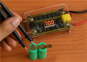
- Test the System: Power the circuit and monitor the LCD for status updates. Verify the relays are working as expected based on voltage thresholds.
Applications
Solar charge controllers
Battery protection systems
DIY battery management systems
This project ensures the longevity of your battery by preventing overcharging and deep discharging. With a straightforward design and reliable components, you can easily build your own 12V Battery Autocut System.
Video Reference:

Build a 12V Battery Autocut System with LCD Display
*PCBWay community is a sharing platform. We are not responsible for any design issues and parameter issues (board thickness, surface finish, etc.) you choose.


Raspberry Pi 5 7 Inch Touch Screen IPS 1024x600 HD LCD HDMI-compatible Display for RPI 4B 3B+ OPI 5 AIDA64 PC Secondary Screen(Without Speaker)
BUY NOW


- Comments(0)
- Likes(3)
 More by Estiak Khan
-
 ⚡ How to Make a DIY Spot Welding Machine at Home for 18650 Batteries | Full Circuit & Working
If you’re working on battery pack projects using 18650 lithium-ion cells, then you know how importan...
⚡ How to Make a DIY Spot Welding Machine at Home for 18650 Batteries | Full Circuit & Working
If you’re working on battery pack projects using 18650 lithium-ion cells, then you know how importan...
-
 🔋 How to Make a Simple DIY Wi-Fi Router UPS at Home | Step-by-Step Guide with Circuit & PCB
Do you lose internet connection every time the power goes out?If yes, then this simple DIY Wi-Fi Rou...
🔋 How to Make a Simple DIY Wi-Fi Router UPS at Home | Step-by-Step Guide with Circuit & PCB
Do you lose internet connection every time the power goes out?If yes, then this simple DIY Wi-Fi Rou...
-
 Automatic AC Changeover for Inverter
 – DIY Circuit GuideAre you tired of manually switching between ...
Automatic AC Changeover for Inverter
Automatic AC Changeover for Inverter – DIY Circuit GuideAre you tired of manually switching between ...
-
 How to Make a 12V AC/DC Fan Controller Module
If you're looking for an efficient way to control a 12V fan using either AC or DC input, this DIY pr...
How to Make a 12V AC/DC Fan Controller Module
If you're looking for an efficient way to control a 12V fan using either AC or DC input, this DIY pr...
-
 Autocut DC Mini IPS for DC 12V Load
If you are looking for a reliable Autocut DC Mini IPS for DC 12V ...
Autocut DC Mini IPS for DC 12V Load
Autocut DC Mini IPS for DC 12V LoadIf you are looking for a reliable Autocut DC Mini IPS for DC 12V ...
-
 Build a 12V Battery Autocut System with LCD Display
Are you looking for an efficient and affordable way to protect and monitor your 12V battery system? ...
Build a 12V Battery Autocut System with LCD Display
Are you looking for an efficient and affordable way to protect and monitor your 12V battery system? ...
-
 DIY Transistor Tester | Build Your Own LCR Meter at Home with Arduino Nano
Are you fascinated by electronics and want to create your own tools for testing components? Building...
DIY Transistor Tester | Build Your Own LCR Meter at Home with Arduino Nano
Are you fascinated by electronics and want to create your own tools for testing components? Building...
-
 How to Make a Pure Sine Wave Inverter Using EG8010 + IR2110S | Step-by-Step Guide
If you are looking ...
How to Make a Pure Sine Wave Inverter Using EG8010 + IR2110S | Step-by-Step Guide
How to Make a Pure Sine Wave Inverter Using EG8010 + IR2110S | Step-by-Step GuideIf you are looking ...
-
 🔋 How to Make DC Changeover for Automatic Inverter System | DIY Inverter Changeover Switch
Are you tired of manually switching between DC power supply and battery backup during load shedding?...
🔋 How to Make DC Changeover for Automatic Inverter System | DIY Inverter Changeover Switch
Are you tired of manually switching between DC power supply and battery backup during load shedding?...
-
 No Need Adapter 🤔 WiFi Router UPS Making with Transformer
No Need Adapter WiFi Router UPS Making with Transformer | Complete Circuit DiagramAre you tired of ...
No Need Adapter 🤔 WiFi Router UPS Making with Transformer
No Need Adapter WiFi Router UPS Making with Transformer | Complete Circuit DiagramAre you tired of ...
-
 🔋 How to Make a Power Bank Module at Home
Are you looking to build your own DIY power bank at home? In this blog post, we’ll show you how to c...
🔋 How to Make a Power Bank Module at Home
Are you looking to build your own DIY power bank at home? In this blog post, we’ll show you how to c...
-
 Cute LIT 220W Inverter Load Test ⚡ Auto Changeover IPS System Explained! 🔋 Real Load Backup Test
Are you looking for a reliable backup power solution for your WiFi router, CCTV, or small appliances...
Cute LIT 220W Inverter Load Test ⚡ Auto Changeover IPS System Explained! 🔋 Real Load Backup Test
Are you looking for a reliable backup power solution for your WiFi router, CCTV, or small appliances...
-
 ⚡ Hybrid WiFi Router UPS for Solar System
IntroductionPower cuts in off-grid areas can disrupt internet connectivity. With the rise of solar s...
⚡ Hybrid WiFi Router UPS for Solar System
IntroductionPower cuts in off-grid areas can disrupt internet connectivity. With the rise of solar s...
-
 🔋 DIY Solar-Based Mini IPS at Home | Auto Load Changeover Circuit for 12V DC Fan/Light
If you're looking for an easy and affordable solution to keep your 12V DC fan or light running even ...
🔋 DIY Solar-Based Mini IPS at Home | Auto Load Changeover Circuit for 12V DC Fan/Light
If you're looking for an easy and affordable solution to keep your 12V DC fan or light running even ...
-
 🔋 DIY Automatic Cut Off 12V Trickle Charger | Lead Acid Battery AutoCut Charger
Do you often charge your 12V lead-acid battery manually and worry about overcharging? With this DIY ...
🔋 DIY Automatic Cut Off 12V Trickle Charger | Lead Acid Battery AutoCut Charger
Do you often charge your 12V lead-acid battery manually and worry about overcharging? With this DIY ...
-
 🔥 DIY Smart 12V Battery at Home | Using 18650 Cells + Smart BMS
Looking for a way to build a powerful and smart 12V battery at home? In this guide, I'll show you h...
🔥 DIY Smart 12V Battery at Home | Using 18650 Cells + Smart BMS
Looking for a way to build a powerful and smart 12V battery at home? In this guide, I'll show you h...
-
 🎮 DIY Arduino Nano Snake Game Console with OLED Display
DIY Arduino Nano Snake Game Console with OLED Display and ButtonsDo you love retro games? Want to bu...
🎮 DIY Arduino Nano Snake Game Console with OLED Display
DIY Arduino Nano Snake Game Console with OLED Display and ButtonsDo you love retro games? Want to bu...
-
 DIY 150W IPS Making At Home with Auto Changeover System | Mini IPS 2025
How to Make an Automatic 150W IPS Using Two Circuit ModulesAre you looking for a reliable and effici...
DIY 150W IPS Making At Home with Auto Changeover System | Mini IPS 2025
How to Make an Automatic 150W IPS Using Two Circuit ModulesAre you looking for a reliable and effici...
-
Programmable Mist Maker - XIAO / QT PY Extension
172 0 0 -
RadioHAT - Raspberry Pi radio development platform
182 0 1 -
-
-
-
-
ARPS-2 – Arduino-Compatible Robot Project Shield for Arduino UNO
2767 0 5 -
A Compact Charging Breakout Board For Waveshare ESP32-C3
3275 3 8 -
AI-driven LoRa & LLM-enabled Kiosk & Food Delivery System
3529 2 2


