


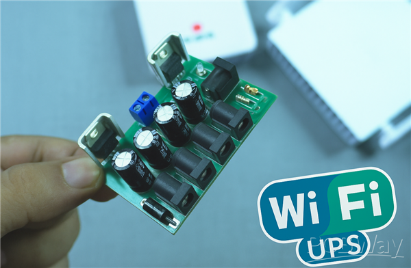
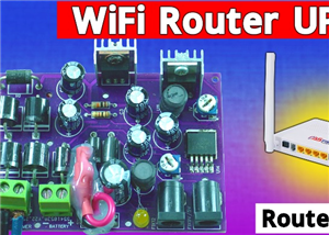
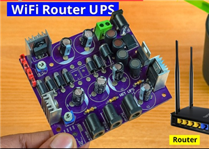
🔋 How to Make a Simple DIY Wi-Fi Router UPS at Home | Step-by-Step Guide with Circuit & PCB
Do you lose internet connection every time the power goes out?
If yes, then this simple DIY Wi-Fi Router UPS project is just what you need!
This small backup power system automatically switches to battery power during a power cut, keeping your Wi-Fi router or modem running without interruption.
It’s easy to build, affordable, and super useful for every home.
🧠 What is a Wi-Fi Router UPS?
A Wi-Fi Router UPS (Uninterruptible Power Supply) provides backup power to your router when electricity fails.
It seamlessly switches between adapter power and battery power using a smart MOSFET circuit.
This design provides 12V, 9V, and 5V outputs, making it compatible with all types of routers and modems.
⚙️ Components Required
Here’s the complete list of components you’ll need for this project:
1 × DC Power Jack (DC-072-165A) – for input
1 × DC Power Jack (DC-072-165A) – for output
1 × Diode 1N5408 – reverse polarity protection
1 × Diode FR508 – power isolation
2 × Diode 1N5822 – Schottky diodes for battery switching
1 × MOSFET IRF9540 – P-channel for automatic switching
1 × Resistor 1KΩ – gate resistor for MOSFET
1 × Voltage Regulator LM7809 – for 9V output
1 × Voltage Regulator LM7805 – for 5V output
4 × Capacitor 10µF – for voltage filtering
1 × 18650 Li-ion Battery (with BMS) – power backup
1 × PCB Board – for circuit assembly
📘 Circuit Diagram Explanation
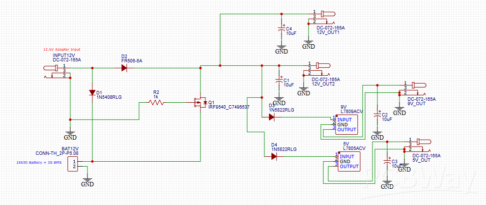
This schematic shows the automatic UPS switching circuit for your Wi-Fi router.
Here’s how it works step by step:
Normal Mode (Adapter ON):
The 12V adapter supplies power directly to the router and charges the battery simultaneously.
The MOSFET (Q1) remains off, isolating the battery from the output.
Power Cut Mode (Adapter OFF):
When the adapter is disconnected, the MOSFET turns on automatically.
The battery output instantly takes over and keeps the router running without interruption.
Voltage Regulation:
The LM7809 and LM7805 ICs provide stable 9V and 5V outputs for routers or USB modems needing lower voltages.
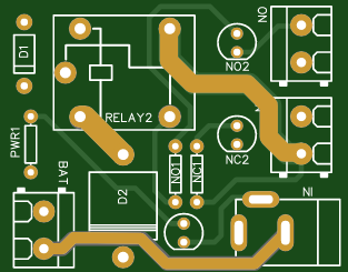
🧩 PCB Layout Design
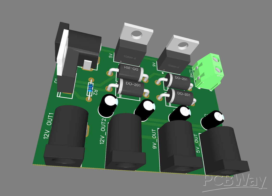
🖋 PCB Design (Top View)
The PCB layout is compact and well-labeled.
It includes three separate outputs — 12V, 9V, and 5V — to support various router models.
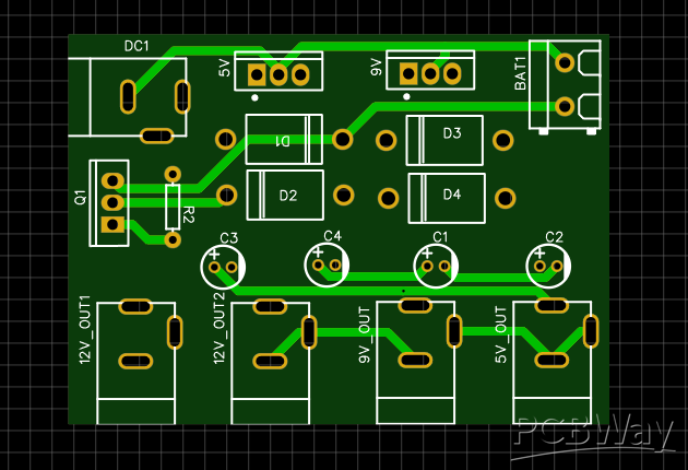
🔍 PCB Routing and Traces
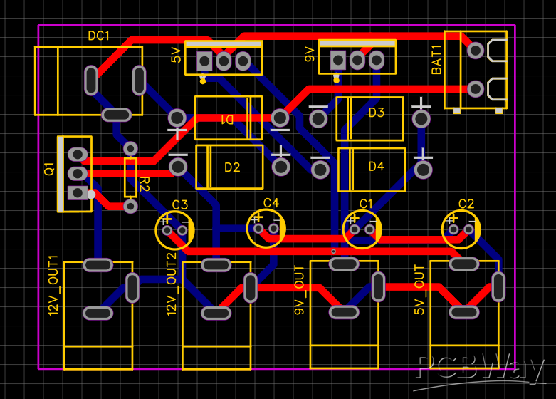
The red traces represent the VCC layer, and the blue traces represent GND connections.
The routing ensures smooth power flow with minimal interference.
🛠 Step-by-Step Assembly Guide
Solder the diodes (D1–D4) as per the circuit diagram.
Place and solder the MOSFET (IRF9540) with a small heatsink if possible.
Add the resistor (R2 – 1KΩ) to the MOSFET gate.
Install the LM7809 and LM7805 voltage regulators for 9V and 5V outputs.
Solder all capacitors (10µF) to stabilize the voltage.
Attach the DC jacks for power input, battery, and output ports.
Connect the 18650 battery with a BMS module for protection.
Double-check polarity before powering on the circuit.
Output Testing
- 12V output — expected: ~12.0V — use: standard 12V routers.
- 9V output — expected: ~9.0V — use: routers that require 9V.
- 5V output — expected: ~5.0V — use: USB Wi-Fi dongles or modems.
- Multimeter check — step 1: set meter to DC volts and measure at each output jack with adapter ON.
- Multimeter check — step 2: record voltages at 12V, 9V, and 5V outputs; they should be within ±0.2V of nominal.
- Load test — step 1: connect the actual router (or a dummy load resistor sized for the router current) to the 12V output.
- Load test — step 2: verify the router powers up and runs stably for several minutes with the adapter ON.
- Switch-over test — step 1: while the router is running on adapter power, unplug the adapter to simulate power loss.
- Switch-over test — step 2: confirm the router stays powered and the battery takes over instantly (no reboot).
- Battery runtime test — step 1: with adapter OFF, run the router from battery and measure how long it lasts; note the runtime and battery voltage drop.
- Regulator heat check — step: after a 30–60 minute load test, carefully feel LM7809/LM7805 and MOSFET heat; add heatsinks if too hot.
- Diode drop check — step: measure voltage before and after Schottky diodes (D3/D4); expect small drop (~0.2–0.5V).
- Safety check — step: confirm BMS is present and battery temperature stays normal during discharge/charge.
- Final verification — step: reconnect adapter and ensure battery recharges and system returns to normal adapter-powered state.
🧾 Advantages of This DIY Wi-Fi Router UPS
🔋 Provides uninterrupted internet connection during power cuts
💡 Uses simple and affordable components
🔌 Offers multiple voltage outputs (12V, 9V, 5V)
🔥 Prevents router restarts during short power outages
🧠 Perfect for beginners and hobbyists
🎥Video Reference
🧰 Applications
Wi-Fi Routers and Modems
CCTV Cameras
Raspberry Pi and IoT devices
Any small DC-powered gadget
🧠 Pro Tips
Use a high-capacity 18650 battery (2200mAh or more) for longer backup time.
Always include a Battery Management System (BMS) for safety.
Add heatsinks to voltage regulators if your router draws high current.
You can enclose the PCB in a 3D-printed or plastic case for a professional look.
🧩 Conclusion
Building your own DIY Wi-Fi Router UPS is an easy and rewarding project.
It ensures your internet stays connected during power cuts, keeps your router safe, and can even power multiple devices at different voltages.
🔋 How to Make a Simple DIY Wi-Fi Router UPS at Home | Step-by-Step Guide with Circuit & PCB
*PCBWay community is a sharing platform. We are not responsible for any design issues and parameter issues (board thickness, surface finish, etc.) you choose.


Raspberry Pi 5 7 Inch Touch Screen IPS 1024x600 HD LCD HDMI-compatible Display for RPI 4B 3B+ OPI 5 AIDA64 PC Secondary Screen(Without Speaker)
BUY NOW


- Comments(0)
- Likes(3)
 More by Estiak Khan
-
 ⚡ How to Make a DIY Spot Welding Machine at Home for 18650 Batteries | Full Circuit & Working
If you’re working on battery pack projects using 18650 lithium-ion cells, then you know how importan...
⚡ How to Make a DIY Spot Welding Machine at Home for 18650 Batteries | Full Circuit & Working
If you’re working on battery pack projects using 18650 lithium-ion cells, then you know how importan...
-
 🔋 How to Make a Simple DIY Wi-Fi Router UPS at Home | Step-by-Step Guide with Circuit & PCB
Do you lose internet connection every time the power goes out?If yes, then this simple DIY Wi-Fi Rou...
🔋 How to Make a Simple DIY Wi-Fi Router UPS at Home | Step-by-Step Guide with Circuit & PCB
Do you lose internet connection every time the power goes out?If yes, then this simple DIY Wi-Fi Rou...
-
 Automatic AC Changeover for Inverter
 – DIY Circuit GuideAre you tired of manually switching between ...
Automatic AC Changeover for Inverter
Automatic AC Changeover for Inverter – DIY Circuit GuideAre you tired of manually switching between ...
-
 How to Make a 12V AC/DC Fan Controller Module
If you're looking for an efficient way to control a 12V fan using either AC or DC input, this DIY pr...
How to Make a 12V AC/DC Fan Controller Module
If you're looking for an efficient way to control a 12V fan using either AC or DC input, this DIY pr...
-
 Autocut DC Mini IPS for DC 12V Load
If you are looking for a reliable Autocut DC Mini IPS for DC 12V ...
Autocut DC Mini IPS for DC 12V Load
Autocut DC Mini IPS for DC 12V LoadIf you are looking for a reliable Autocut DC Mini IPS for DC 12V ...
-
 Build a 12V Battery Autocut System with LCD Display
Are you looking for an efficient and affordable way to protect and monitor your 12V battery system? ...
Build a 12V Battery Autocut System with LCD Display
Are you looking for an efficient and affordable way to protect and monitor your 12V battery system? ...
-
 DIY Transistor Tester | Build Your Own LCR Meter at Home with Arduino Nano
Are you fascinated by electronics and want to create your own tools for testing components? Building...
DIY Transistor Tester | Build Your Own LCR Meter at Home with Arduino Nano
Are you fascinated by electronics and want to create your own tools for testing components? Building...
-
 How to Make a Pure Sine Wave Inverter Using EG8010 + IR2110S | Step-by-Step Guide
If you are looking ...
How to Make a Pure Sine Wave Inverter Using EG8010 + IR2110S | Step-by-Step Guide
How to Make a Pure Sine Wave Inverter Using EG8010 + IR2110S | Step-by-Step GuideIf you are looking ...
-
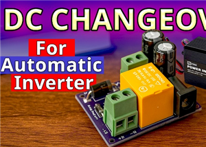 🔋 How to Make DC Changeover for Automatic Inverter System | DIY Inverter Changeover Switch
Are you tired of manually switching between DC power supply and battery backup during load shedding?...
🔋 How to Make DC Changeover for Automatic Inverter System | DIY Inverter Changeover Switch
Are you tired of manually switching between DC power supply and battery backup during load shedding?...
-
 No Need Adapter 🤔 WiFi Router UPS Making with Transformer
No Need Adapter WiFi Router UPS Making with Transformer | Complete Circuit DiagramAre you tired of ...
No Need Adapter 🤔 WiFi Router UPS Making with Transformer
No Need Adapter WiFi Router UPS Making with Transformer | Complete Circuit DiagramAre you tired of ...
-
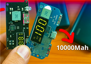 🔋 How to Make a Power Bank Module at Home
Are you looking to build your own DIY power bank at home? In this blog post, we’ll show you how to c...
🔋 How to Make a Power Bank Module at Home
Are you looking to build your own DIY power bank at home? In this blog post, we’ll show you how to c...
-
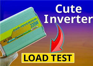 Cute LIT 220W Inverter Load Test ⚡ Auto Changeover IPS System Explained! 🔋 Real Load Backup Test
Are you looking for a reliable backup power solution for your WiFi router, CCTV, or small appliances...
Cute LIT 220W Inverter Load Test ⚡ Auto Changeover IPS System Explained! 🔋 Real Load Backup Test
Are you looking for a reliable backup power solution for your WiFi router, CCTV, or small appliances...
-
 ⚡ Hybrid WiFi Router UPS for Solar System
IntroductionPower cuts in off-grid areas can disrupt internet connectivity. With the rise of solar s...
⚡ Hybrid WiFi Router UPS for Solar System
IntroductionPower cuts in off-grid areas can disrupt internet connectivity. With the rise of solar s...
-
 🔋 DIY Solar-Based Mini IPS at Home | Auto Load Changeover Circuit for 12V DC Fan/Light
If you're looking for an easy and affordable solution to keep your 12V DC fan or light running even ...
🔋 DIY Solar-Based Mini IPS at Home | Auto Load Changeover Circuit for 12V DC Fan/Light
If you're looking for an easy and affordable solution to keep your 12V DC fan or light running even ...
-
 🔋 DIY Automatic Cut Off 12V Trickle Charger | Lead Acid Battery AutoCut Charger
Do you often charge your 12V lead-acid battery manually and worry about overcharging? With this DIY ...
🔋 DIY Automatic Cut Off 12V Trickle Charger | Lead Acid Battery AutoCut Charger
Do you often charge your 12V lead-acid battery manually and worry about overcharging? With this DIY ...
-
 🔥 DIY Smart 12V Battery at Home | Using 18650 Cells + Smart BMS
Looking for a way to build a powerful and smart 12V battery at home? In this guide, I'll show you h...
🔥 DIY Smart 12V Battery at Home | Using 18650 Cells + Smart BMS
Looking for a way to build a powerful and smart 12V battery at home? In this guide, I'll show you h...
-
 🎮 DIY Arduino Nano Snake Game Console with OLED Display
DIY Arduino Nano Snake Game Console with OLED Display and ButtonsDo you love retro games? Want to bu...
🎮 DIY Arduino Nano Snake Game Console with OLED Display
DIY Arduino Nano Snake Game Console with OLED Display and ButtonsDo you love retro games? Want to bu...
-
 DIY 150W IPS Making At Home with Auto Changeover System | Mini IPS 2025
How to Make an Automatic 150W IPS Using Two Circuit ModulesAre you looking for a reliable and effici...
DIY 150W IPS Making At Home with Auto Changeover System | Mini IPS 2025
How to Make an Automatic 150W IPS Using Two Circuit ModulesAre you looking for a reliable and effici...
-
-
ARPS-2 – Arduino-Compatible Robot Project Shield for Arduino UNO
2280 0 5 -
A Compact Charging Breakout Board For Waveshare ESP32-C3
2761 3 7 -
AI-driven LoRa & LLM-enabled Kiosk & Food Delivery System
2958 2 0 -
-
-
-
ESP32-C3 BLE Keyboard - Battery Powered with USB-C Charging
3000 0 2 -


