


|
|
6A10-TP |
x 1 | |
|
|
DC_RELAY |
x 1 | |
|
|
LED-5mm Round Yellow |
x 1 | |
|
|
1k |
x 1 | |
|
|
1u |
x 1 |
🚀 DIY Long Backup Mini DC IPS | Make at Home Using a UPS Transformer! 💡
🚀 DIY Long Backup Mini DC IPS | Make at Home Using a UPS Transformer! 💡

Introduction
Building a Mini DC IPS (Instant Power Supply) at home can be a rewarding project that equips you with a backup power solution for low-power DC appliances. This tutorial will guide you step-by-step through the process of creating a 10A Mini DC IPS using readily available components. With a well-designed circuit and attention to detail, you’ll have a reliable DC power backup system in no time.
Whether you’re an electronics enthusiast or just starting out, this guide provides comprehensive instructions and insights to ensure success.
Key Features of the Mini DC IPS
- Compact and Portable: Small enough for home or DIY workshop use.
- High Current Capacity: Delivers up to 10A output, suitable for most DC devices.
- Relay-Controlled Load Management: Ensures seamless switching and control of connected loads.
- LED Indicators: Provides real-time feedback on power and load status.
- Safe Design: Includes protection features to prevent component damage.
- Easy-to-Build Circuit: Designed with simplicity and efficiency in mind, perfect for DIYers.
Components Required
- Rectifier Diodes: 6A10 (x5)
- Capacitors: 1000µF (U2), 680nF (C1)
- Resistors: 1kΩ (PWR1, NO, NC pins of the relay)
- Relay: 5V (LOAD1)
- LED Indicators: 5mm Red LEDs for power and relay status
- Flyback Diode: 1N4007 (DS)
- Connectors: CONN_TH_2P/3P for battery and AC input
- Transformer: AC 220V primary to 12V secondary (not included in the schematic)
- PCB or Breadboard
- Wires and Connectors
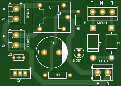
Understanding the Circuit Diagram
Below is an overview of the circuit's main sections, designed for simplicity and efficiency. The attached schematic diagram will help you follow along as you assemble the components.
Bridge Rectifier:
Four diodes (D1–D4) form a bridge rectifier, converting the AC input (220V) to DC voltage.
This is essential for powering the relay and other DC components in the circuit.
Voltage Filtering and Smoothing:
Capacitors (1000µF and 680nF) stabilize the rectified DC, reducing voltage fluctuations.
This ensures a clean power supply for the relay and connected devices.
Relay Operation:
The 5V relay (LOAD1) manages the connection between the DC load and the power source.
Resistors control current flow to the relay and LED indicators, while the flyback diode (1N4007) protects the circuit from voltage spikes.
LED Indicators:
Three LEDs provide status feedback:
- Power LED (PWR): Lights up when the system is powered.
- NC LED: Indicates the normally closed state of the relay.
- NO LED: Indicates the normally open state of the relay.
Load and Battery Connections:
Clear terminals are provided for the DC load and battery input, making the system user-friendly.

Step-by-Step Assembly Instructions
Gather Your Tools and Components:
Tools required: Soldering iron, multimeter, wire cutter, and a small screwdriver.
Double-check all components to ensure they meet the required specifications.
Set Up the Bridge Rectifier:
Arrange the four diodes (D1–D4) in a bridge configuration.
Connect the AC input to the rectifier and verify the DC output using a multimeter.
Add Filtering Capacitors:
Solder the 1000µF and 680nF capacitors to the rectifier output.
Ensure correct polarity for the electrolytic capacitor (1000µF).
Wire the Relay and Flyback Diode:
Connect the relay coil to the DC supply through a 1kΩ resistor.
Place the flyback diode (1N4007) across the relay coil to prevent voltage spikes.
Install the LED Indicators:
Connect the LEDs to the respective points in the circuit.
Use resistors to limit current and prevent LED damage.
Test the Circuit:
Power the circuit and check for LED illumination.
Verify relay operation by connecting a small DC load (e.g., a 12V LED light or fan).
Secure on a PCB:
After testing, transfer the circuit to a PCB or custom board for a durable setup.
Common Issues and Troubleshooting
- Problem: LEDs do not light up.
- Solution: Check for loose connections or incorrect polarity of components.
- Problem: Relay does not activate.
- Solution: Verify the voltage at the relay coil and check the flyback diode orientation.
- Problem: Output voltage fluctuates.
- Solution: Ensure the capacitors are properly soldered and functional.
Applications of the Mini DC IPS
- Emergency Power Supply: Provides backup for low-power DC appliances like LED lights and fans.
- Portable Electronics: Perfect for powering small electronics in off-grid scenarios.
- DIY Hobby Projects: Acts as a power source for experimenting with DC devices.
SEO Keywords
To improve search engine visibility, this post includes the following targeted keywords:
- DIY Mini DC IPS
- 10A DC power supply
- Compact IPS project
- Home electronics DIY
- AC to DC power circuit
- DC load relay control
- Build IPS at home
Video Reference:
Conclusion
This DIY Mini DC IPS project is a simple yet effective way to gain hands-on experience with electronics. With minimal components and straightforward assembly, you can create a reliable backup power system for your home or workshop. By following this detailed guide and using the provided circuit diagram, you’ll have a functional and efficient IPS ready in no time.
Don’t forget to share your experience and improvements in the comments!
🚀 DIY Long Backup Mini DC IPS | Make at Home Using a UPS Transformer! 💡
*PCBWay community is a sharing platform. We are not responsible for any design issues and parameter issues (board thickness, surface finish, etc.) you choose.


- Comments(0)
- Likes(1)
 More by Estiak Khan
-
 ⚡ How to Make a DIY Spot Welding Machine at Home for 18650 Batteries | Full Circuit & Working
If you’re working on battery pack projects using 18650 lithium-ion cells, then you know how importan...
⚡ How to Make a DIY Spot Welding Machine at Home for 18650 Batteries | Full Circuit & Working
If you’re working on battery pack projects using 18650 lithium-ion cells, then you know how importan...
-
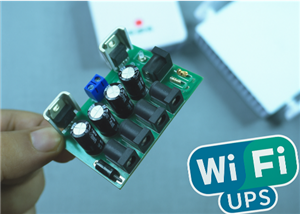 🔋 How to Make a Simple DIY Wi-Fi Router UPS at Home | Step-by-Step Guide with Circuit & PCB
Do you lose internet connection every time the power goes out?If yes, then this simple DIY Wi-Fi Rou...
🔋 How to Make a Simple DIY Wi-Fi Router UPS at Home | Step-by-Step Guide with Circuit & PCB
Do you lose internet connection every time the power goes out?If yes, then this simple DIY Wi-Fi Rou...
-
 Automatic AC Changeover for Inverter
 – DIY Circuit GuideAre you tired of manually switching between ...
Automatic AC Changeover for Inverter
Automatic AC Changeover for Inverter – DIY Circuit GuideAre you tired of manually switching between ...
-
 How to Make a 12V AC/DC Fan Controller Module
If you're looking for an efficient way to control a 12V fan using either AC or DC input, this DIY pr...
How to Make a 12V AC/DC Fan Controller Module
If you're looking for an efficient way to control a 12V fan using either AC or DC input, this DIY pr...
-
 Autocut DC Mini IPS for DC 12V Load
If you are looking for a reliable Autocut DC Mini IPS for DC 12V ...
Autocut DC Mini IPS for DC 12V Load
Autocut DC Mini IPS for DC 12V LoadIf you are looking for a reliable Autocut DC Mini IPS for DC 12V ...
-
 Build a 12V Battery Autocut System with LCD Display
Are you looking for an efficient and affordable way to protect and monitor your 12V battery system? ...
Build a 12V Battery Autocut System with LCD Display
Are you looking for an efficient and affordable way to protect and monitor your 12V battery system? ...
-
 DIY Transistor Tester | Build Your Own LCR Meter at Home with Arduino Nano
Are you fascinated by electronics and want to create your own tools for testing components? Building...
DIY Transistor Tester | Build Your Own LCR Meter at Home with Arduino Nano
Are you fascinated by electronics and want to create your own tools for testing components? Building...
-
 How to Make a Pure Sine Wave Inverter Using EG8010 + IR2110S | Step-by-Step Guide
If you are looking ...
How to Make a Pure Sine Wave Inverter Using EG8010 + IR2110S | Step-by-Step Guide
How to Make a Pure Sine Wave Inverter Using EG8010 + IR2110S | Step-by-Step GuideIf you are looking ...
-
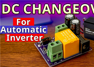 🔋 How to Make DC Changeover for Automatic Inverter System | DIY Inverter Changeover Switch
Are you tired of manually switching between DC power supply and battery backup during load shedding?...
🔋 How to Make DC Changeover for Automatic Inverter System | DIY Inverter Changeover Switch
Are you tired of manually switching between DC power supply and battery backup during load shedding?...
-
 No Need Adapter 🤔 WiFi Router UPS Making with Transformer
No Need Adapter WiFi Router UPS Making with Transformer | Complete Circuit DiagramAre you tired of ...
No Need Adapter 🤔 WiFi Router UPS Making with Transformer
No Need Adapter WiFi Router UPS Making with Transformer | Complete Circuit DiagramAre you tired of ...
-
 🔋 How to Make a Power Bank Module at Home
Are you looking to build your own DIY power bank at home? In this blog post, we’ll show you how to c...
🔋 How to Make a Power Bank Module at Home
Are you looking to build your own DIY power bank at home? In this blog post, we’ll show you how to c...
-
 Cute LIT 220W Inverter Load Test ⚡ Auto Changeover IPS System Explained! 🔋 Real Load Backup Test
Are you looking for a reliable backup power solution for your WiFi router, CCTV, or small appliances...
Cute LIT 220W Inverter Load Test ⚡ Auto Changeover IPS System Explained! 🔋 Real Load Backup Test
Are you looking for a reliable backup power solution for your WiFi router, CCTV, or small appliances...
-
 ⚡ Hybrid WiFi Router UPS for Solar System
IntroductionPower cuts in off-grid areas can disrupt internet connectivity. With the rise of solar s...
⚡ Hybrid WiFi Router UPS for Solar System
IntroductionPower cuts in off-grid areas can disrupt internet connectivity. With the rise of solar s...
-
 🔋 DIY Solar-Based Mini IPS at Home | Auto Load Changeover Circuit for 12V DC Fan/Light
If you're looking for an easy and affordable solution to keep your 12V DC fan or light running even ...
🔋 DIY Solar-Based Mini IPS at Home | Auto Load Changeover Circuit for 12V DC Fan/Light
If you're looking for an easy and affordable solution to keep your 12V DC fan or light running even ...
-
 🔋 DIY Automatic Cut Off 12V Trickle Charger | Lead Acid Battery AutoCut Charger
Do you often charge your 12V lead-acid battery manually and worry about overcharging? With this DIY ...
🔋 DIY Automatic Cut Off 12V Trickle Charger | Lead Acid Battery AutoCut Charger
Do you often charge your 12V lead-acid battery manually and worry about overcharging? With this DIY ...
-
 🔥 DIY Smart 12V Battery at Home | Using 18650 Cells + Smart BMS
Looking for a way to build a powerful and smart 12V battery at home? In this guide, I'll show you h...
🔥 DIY Smart 12V Battery at Home | Using 18650 Cells + Smart BMS
Looking for a way to build a powerful and smart 12V battery at home? In this guide, I'll show you h...
-
 🎮 DIY Arduino Nano Snake Game Console with OLED Display
DIY Arduino Nano Snake Game Console with OLED Display and ButtonsDo you love retro games? Want to bu...
🎮 DIY Arduino Nano Snake Game Console with OLED Display
DIY Arduino Nano Snake Game Console with OLED Display and ButtonsDo you love retro games? Want to bu...
-
 DIY 150W IPS Making At Home with Auto Changeover System | Mini IPS 2025
How to Make an Automatic 150W IPS Using Two Circuit ModulesAre you looking for a reliable and effici...
DIY 150W IPS Making At Home with Auto Changeover System | Mini IPS 2025
How to Make an Automatic 150W IPS Using Two Circuit ModulesAre you looking for a reliable and effici...
-
-
-
-
Tester for Touch Screen Digitizer without using microcontroller
337 2 2 -
Audio reactive glow LED wristband/bracelet with NFC / RFID-Tags
317 0 1 -
-
-


