


|
KiCad 8.0KiCad
|
DIY Low Cost Transmitter
Introducing a versatile 4x2 channel remote controller, ideal for managing RC toys, robotics, Arduino projects, and various electronic applications. This transmitter enables individual control over 8 channels, utilizing RF communication for an extended range. Notably, the design excludes microcontrollers, relying instead on common electronic components and readily available RF modules.
Key Components;)
- HT12E Encoder IC: Converts 12 bits of parallel data into serial data for wireless transmission.
- STX882 RF Module: Transmits the encoded data over radio frequencies.
- Power Supply: A 9V battery regulated by an LM7805 IC to provide a stable 5V output.
Transmitter Circuit Overview;)
The transmitter circuit is built around the HT12E encoder IC, which encodes 8 address bits and 4 data bits into a serial format. The address bits ensure communication with the correct receiver, while the data bits represent the control signals. When a button is pressed, the corresponding data input on the HT12E is activated, and the transmission is enabled by pulling the TE pin low. The encoded serial data is then sent to the STX882 RF module, which transmits it wirelessly.
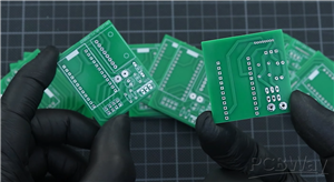
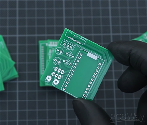
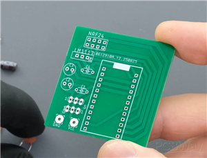
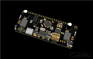
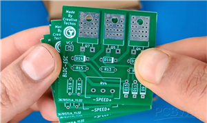
PCB Design;)
The PCB layout is compact, ensuring portability and ease of use. It includes sockets for the HT12E IC, connections for the STX882 module, and appropriate routing for power and signal lines. The design also incorporates a toggle switch for power control and indicator LEDs for transmission status.
Enclosure Design;)
A custom enclosure has been designed to house the transmitter circuit, providing protection and a professional appearance. The enclosure is 3D-printable, with STL files available for the top part, bottom part, and battery cover. Brass hot melt insert nuts are used to secure the assembly, ensuring durability and ease of maintenance.
Assembly Steps;)
- Soldering Components: Assemble the PCB by soldering all components as per the circuit diagram.
- Programming Address Pins: Set the address pins (A0-A7) on the HT12E to match the receiver's address for secure communication.
- Connecting Power Supply: Attach the 9V battery connector to the PCB, ensuring correct polarity.
- Mounting in Enclosure: Place the assembled PCB into the 3D-printed enclosure and secure it using the brass insert nuts and appropriate screws.
- Final Testing: Power on the transmitter and verify functionality by checking the transmission indicator LEDs and ensuring proper communication with the receiver.
This transmitter design offers a cost-effective and efficient solution for wireless control applications, utilizing readily available components and straightforward assembly processes.

DIY Low Cost Transmitter
*PCBWay community is a sharing platform. We are not responsible for any design issues and parameter issues (board thickness, surface finish, etc.) you choose.


Raspberry Pi 5 7 Inch Touch Screen IPS 1024x600 HD LCD HDMI-compatible Display for RPI 4B 3B+ OPI 5 AIDA64 PC Secondary Screen(Without Speaker)
BUY NOW


- Comments(3)
- Likes(0)
More by Nirmal Maa
-
 VC-02 Module Based Home Automation
In this guide, I’ll take you through the process of building a project using a custom-designed PCB, ...
VC-02 Module Based Home Automation
In this guide, I’ll take you through the process of building a project using a custom-designed PCB, ...
-
 PCBWay 12th Anniversary Badge Design
To celebrate the 12th Anniversary of PCBWay, I designed a special interactive electronic badge that ...
PCBWay 12th Anniversary Badge Design
To celebrate the 12th Anniversary of PCBWay, I designed a special interactive electronic badge that ...
-
 16-Array Line Follower Robot Sensor PCB Design
This project presents a purpose-built 16-channel line follower sensor PCB engineered for precision r...
16-Array Line Follower Robot Sensor PCB Design
This project presents a purpose-built 16-channel line follower sensor PCB engineered for precision r...
-
 ESP01 + TM1637 NTP Clock (0.56″ 7-Segment Display)
This project is a minimalist Wi-Fi desk clock built around the ESP-01 / ESP-01S and a 0.56″ TM1637 7...
ESP01 + TM1637 NTP Clock (0.56″ 7-Segment Display)
This project is a minimalist Wi-Fi desk clock built around the ESP-01 / ESP-01S and a 0.56″ TM1637 7...
-
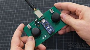 Wireless Dual-Joystick NRF24 Controller PCB for Robotics & RC Applications
This project presents a compact and reliable dual-joystick wireless controller PCB, designed for rob...
Wireless Dual-Joystick NRF24 Controller PCB for Robotics & RC Applications
This project presents a compact and reliable dual-joystick wireless controller PCB, designed for rob...
-
 Channel RC Receiver PCB (NRF24 + Arduino Nano)
This receiver board is the compact, reliable counterpart to the 6-channel transmitter, designed to d...
Channel RC Receiver PCB (NRF24 + Arduino Nano)
This receiver board is the compact, reliable counterpart to the 6-channel transmitter, designed to d...
-
 Compact 3×3 Streaming Macro Pad with RGB & Encoders
The TriPad Studio Controller is a professional-grade 3×3 macro pad designed specifically for streame...
Compact 3×3 Streaming Macro Pad with RGB & Encoders
The TriPad Studio Controller is a professional-grade 3×3 macro pad designed specifically for streame...
-
 Servo & ESC Tester with End-Point Adjustment – (Dual Supply / High-Power)
The Servo & ESC Tester PCB (Dual Supply Version) is designed for applications involving high-tor...
Servo & ESC Tester with End-Point Adjustment – (Dual Supply / High-Power)
The Servo & ESC Tester PCB (Dual Supply Version) is designed for applications involving high-tor...
-
 Servo & ESC Tester with End-Point Adjustment – Single Supply
This Servo & ESC Tester PCB (Single Supply Version) is designed as a compact and reliable tool f...
Servo & ESC Tester with End-Point Adjustment – Single Supply
This Servo & ESC Tester PCB (Single Supply Version) is designed as a compact and reliable tool f...
-
 FPV Head Tracking System – Transmitter PCB
The Transmitter PCB is the sensing and data-sending side of the FPV head tracking system, designed t...
FPV Head Tracking System – Transmitter PCB
The Transmitter PCB is the sensing and data-sending side of the FPV head tracking system, designed t...
-
 FPV Head Tracking System – Receiver PCB (Small Version)
The Small Receiver PCB is the compact counterpart of the FPV head tracking system receiver, designed...
FPV Head Tracking System – Receiver PCB (Small Version)
The Small Receiver PCB is the compact counterpart of the FPV head tracking system receiver, designed...
-
 FPV Head Tracking System – Receiver PCB (Large Version)
This Large Receiver PCB is a core part of a DIY FPV head tracking system, designed to receive head m...
FPV Head Tracking System – Receiver PCB (Large Version)
This Large Receiver PCB is a core part of a DIY FPV head tracking system, designed to receive head m...
-
 N20 Motor Breakout with DRV8212 4A Driver
This N20 Motor Breakout is a compact, motor-mounted driver board built around the DRV8212 H-bridge m...
N20 Motor Breakout with DRV8212 4A Driver
This N20 Motor Breakout is a compact, motor-mounted driver board built around the DRV8212 H-bridge m...
-
 Compact Motion Controller for Competitive Robotics
HMotion is a purpose-built controller PCB designed to simplify and strengthen robotics projects wher...
Compact Motion Controller for Competitive Robotics
HMotion is a purpose-built controller PCB designed to simplify and strengthen robotics projects wher...
-
 LM723 Solar Charge Controller with Voltage & Current Control
This project demonstrates a high-power solar charge controller built around the classic LM723 voltag...
LM723 Solar Charge Controller with Voltage & Current Control
This project demonstrates a high-power solar charge controller built around the classic LM723 voltag...
-
 Transformerless Adjustable AC-to-DC LED Driver (220V AC → 3V–110V DC)
This project explores a transformerless, auto-adjustable LED driver designed to convert 220V AC main...
Transformerless Adjustable AC-to-DC LED Driver (220V AC → 3V–110V DC)
This project explores a transformerless, auto-adjustable LED driver designed to convert 220V AC main...
-
 Adjustable 3.7V Step-Up Boost Converter (5V–30V)
This project presents a compact and efficient step-up boost converter designed to generate higher vo...
Adjustable 3.7V Step-Up Boost Converter (5V–30V)
This project presents a compact and efficient step-up boost converter designed to generate higher vo...
-
 60A Brushless BLDC Motor Controller (ESC)
This project showcases a DIY 60A Brushless DC (BLDC) Motor Controller (ESC) built using N-channel MO...
60A Brushless BLDC Motor Controller (ESC)
This project showcases a DIY 60A Brushless DC (BLDC) Motor Controller (ESC) built using N-channel MO...
-
Programmable Mist Maker - XIAO / QT PY Extension
220 0 0 -
RadioHAT - Raspberry Pi radio development platform
247 0 1 -
-
-
-
-
ARPS-2 – Arduino-Compatible Robot Project Shield for Arduino UNO
2799 0 5 -
A Compact Charging Breakout Board For Waveshare ESP32-C3
3303 3 8 -
AI-driven LoRa & LLM-enabled Kiosk & Food Delivery System
3581 2 2


