


|
|
Beetle Esp32-C3 |
x 1 | |
|
|
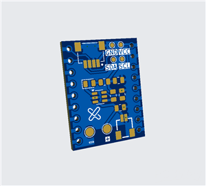
SHTC3 Sensor |
x 1 | |
|
|
0.91 |
x 1 | |
|
|
350mAh Lipo Battery |
x 1 |

|
fusion360 |
|

|
arduino IDEArduino
|
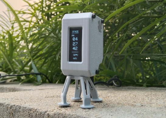
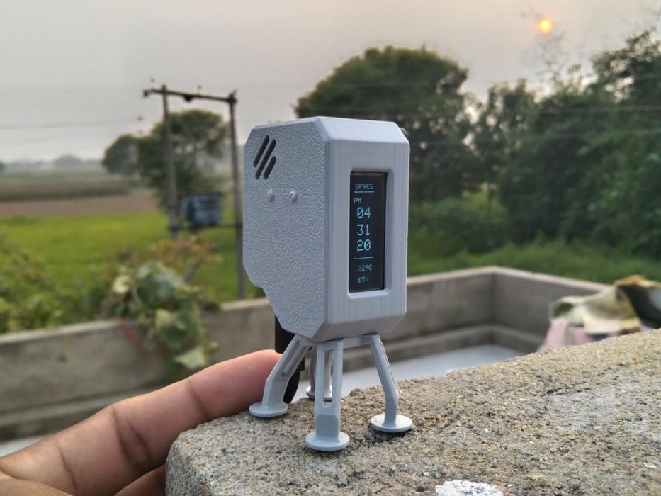
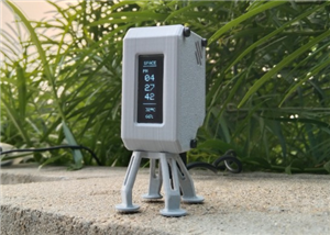
OrbitClock – a Tiny Space-Inspired IoT Environment Clock
Time and space are deeply connected — satellites orbit Earth to keep our clocks synchronized with incredible precision. Inspired by that idea, I created OrbitClock, a tiny space-themed clock that brings the beauty of satellite technology right to your desk.
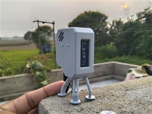
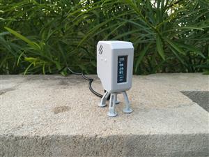
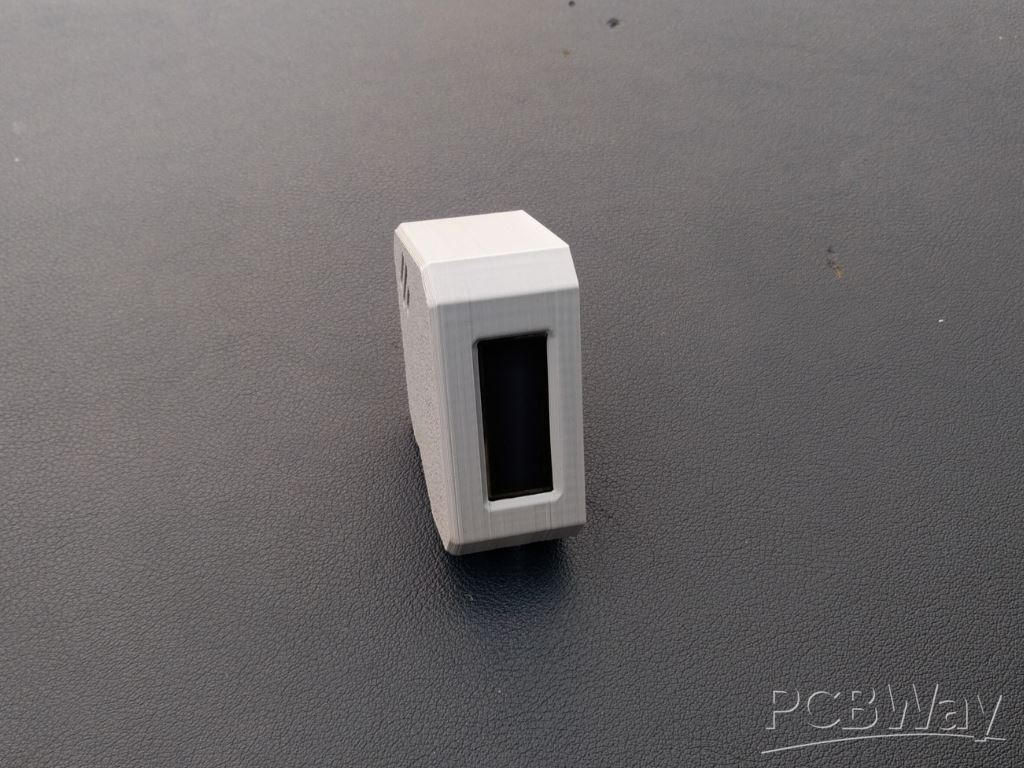
Designed in Autodesk Fusion 360, the OrbitClock’s 3D-printed body stands proudly on four landing-style legs, giving it the look of a mini spacecraft that just touched down on your table. On the front, a 0.91-inch OLED display shows a clean and futuristic readout labeled SPACE, featuring the current time, temperature, and humidity in real time.
Powered by the DFRobot Beetle ESP32-C3, this smart clock connects to Wi-Fi and automatically retrieves the correct time from the internet using Network Time Protocol (NTP) — just like real satellites synchronize with Earth-based systems. The onboard SHTC3 sensor continuously monitors temperature and humidity, providing accurate environmental data alongside the clock display.
With its sleek design, glowing display, and precise wireless timekeeping, OrbitClock isn’t just a clock — it’s a mini space instrument observing your surroundings just like satellites observe our planet. 🌍✨

Step 1: CAD & 3D Printing

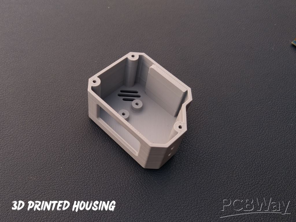
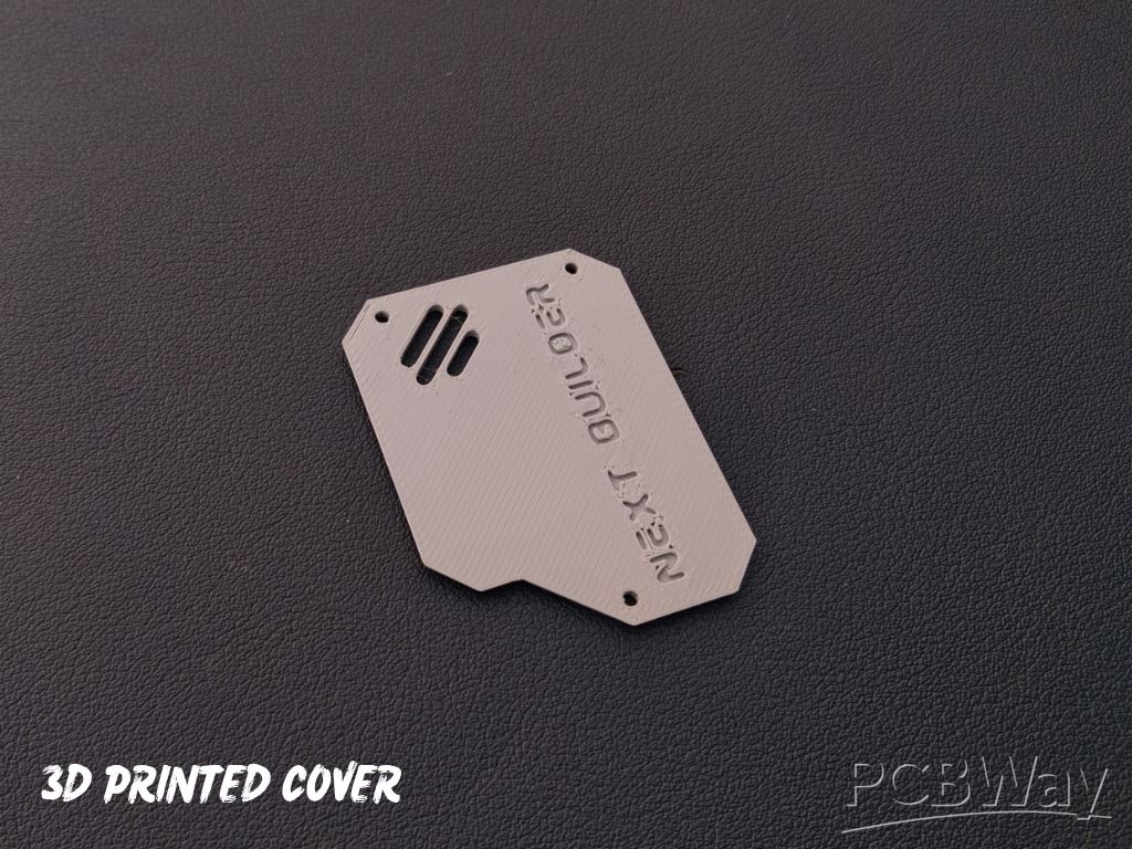
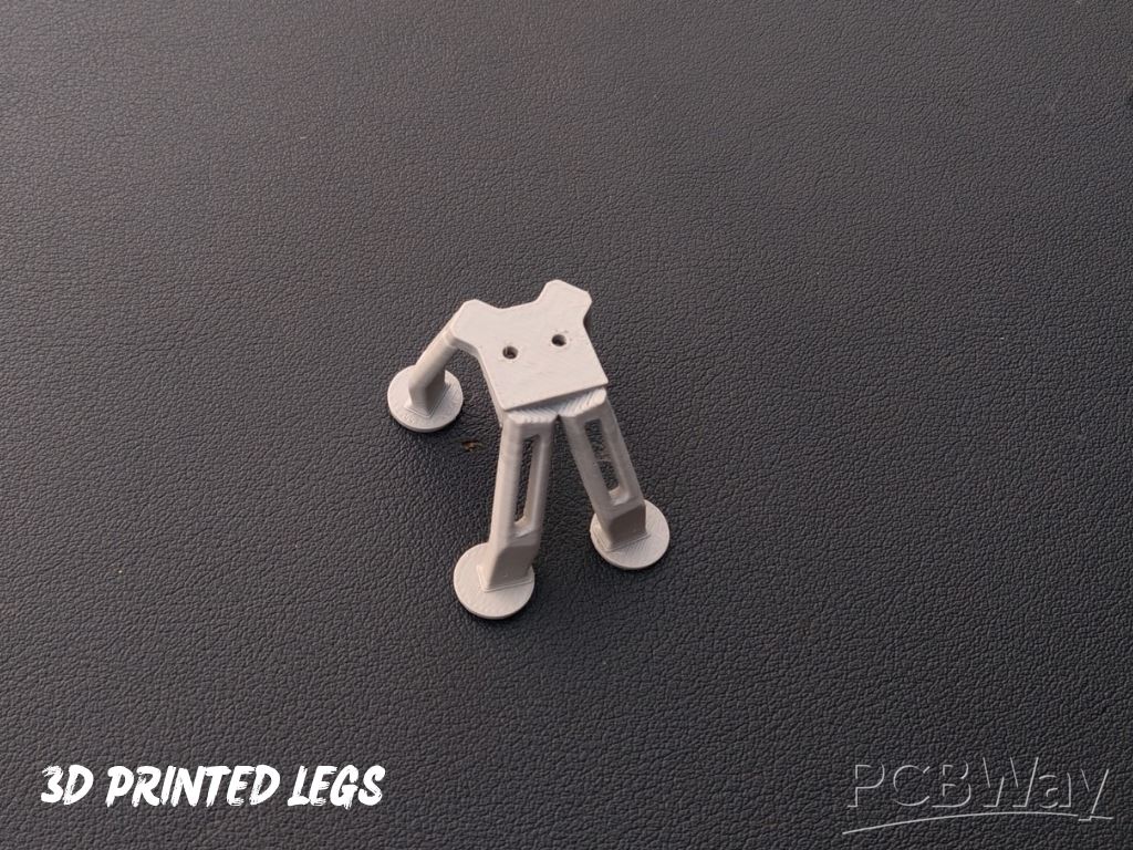 To begin this project, I designed the OrbitClock in Autodesk Fusion 360, carefully keeping all the component dimensions and aesthetics in mind. My goal was to make it small, futuristic, and easy to assemble, just like a real mini satellite.The design features a clean body with a front display window, cooling vents, and landing-style legs that give it a true space-inspired look. It’s also 3D-printing friendly, requiring no complex supports or post-processing.
For 3D Printing, You can directly download the required STL files below:
- Housing.stl
- Cover.stl
- Legs.stl
Step 2: Display Assembly
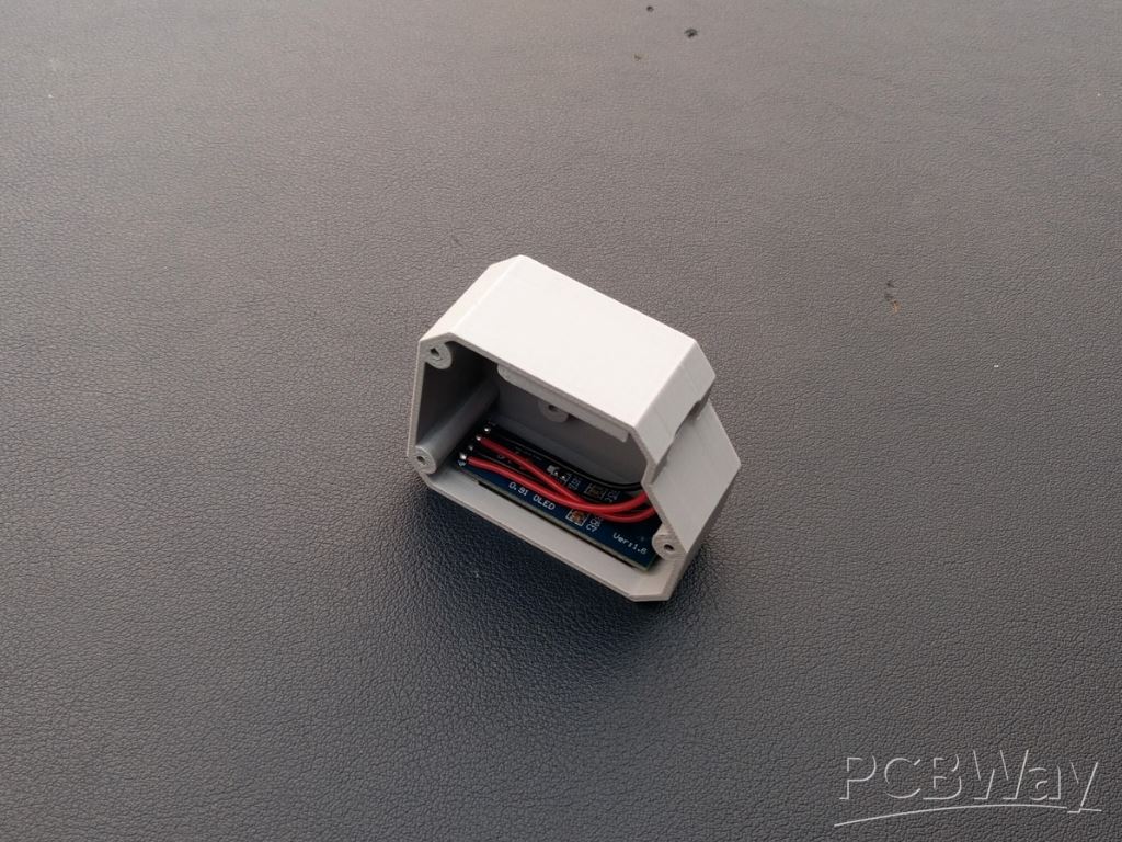
Let’s start by assembling the OLED display into the 3D-printed housing. Before placing it inside, I soldered four wires to the display pins — VCC, GND, SCL, and SDA — so that connecting it to the microcontroller later becomes quick and easy.
Once the wires were attached, I applied a tiny amount of super glue along the edges of the display and carefully fixed it into the dedicated display slot on the front panel. Make sure it’s aligned properly and sits flat for a clean look.
Step 3: Microcontroller Assembly

 After completing the display assembly, it’s time to mount the Beetle ESP32-C3 microcontroller. Apply a small amount of super glue on the back side of the board and carefully place it in its dedicated slot inside the enclosure.
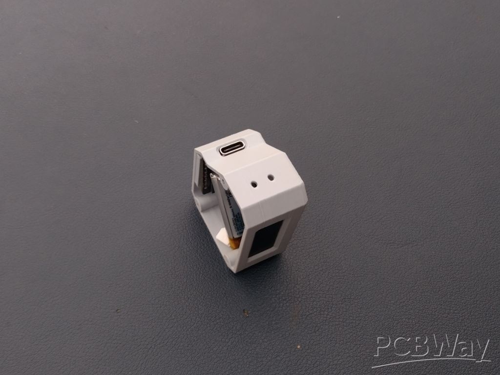
Make sure the Type-C port is perfectly aligned with the opening on the case so that you can easily connect the cable later. Hold it in place for a few seconds until the glue sets properly.
Step 4: Sensor Assembly
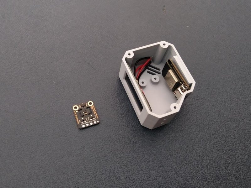
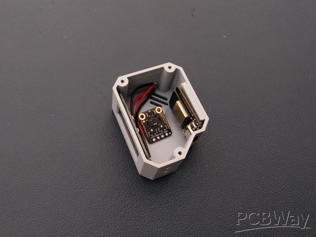
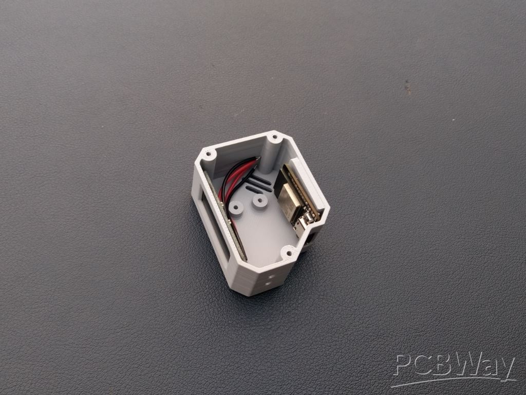
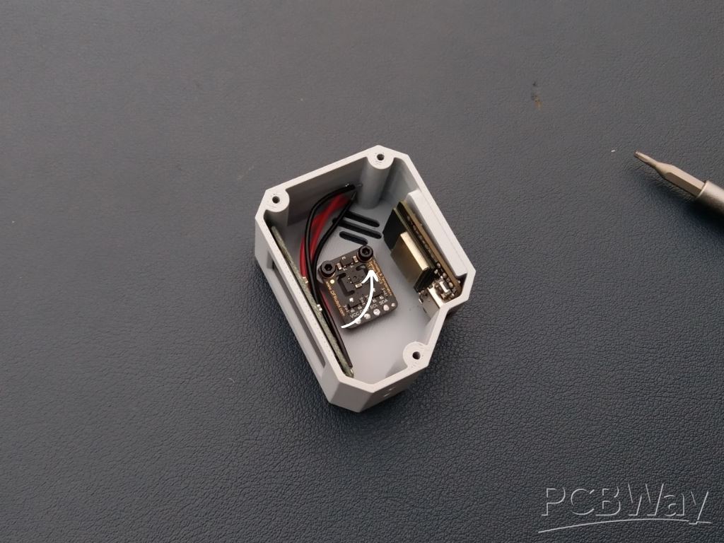 Once the microcontroller is in place, it’s time to install the final main component — the SHTC3 Temperature and Humidity Sensor. Carefully position the sensor in its dedicated slot inside the enclosure. Use two small M3 screws to secure it firmly with the help of a screwdriver. Make sure the sensor is properly aligned and tight enough so it stays fixed during use.
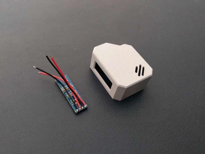
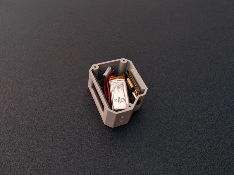
Step 5: Battery Assembly

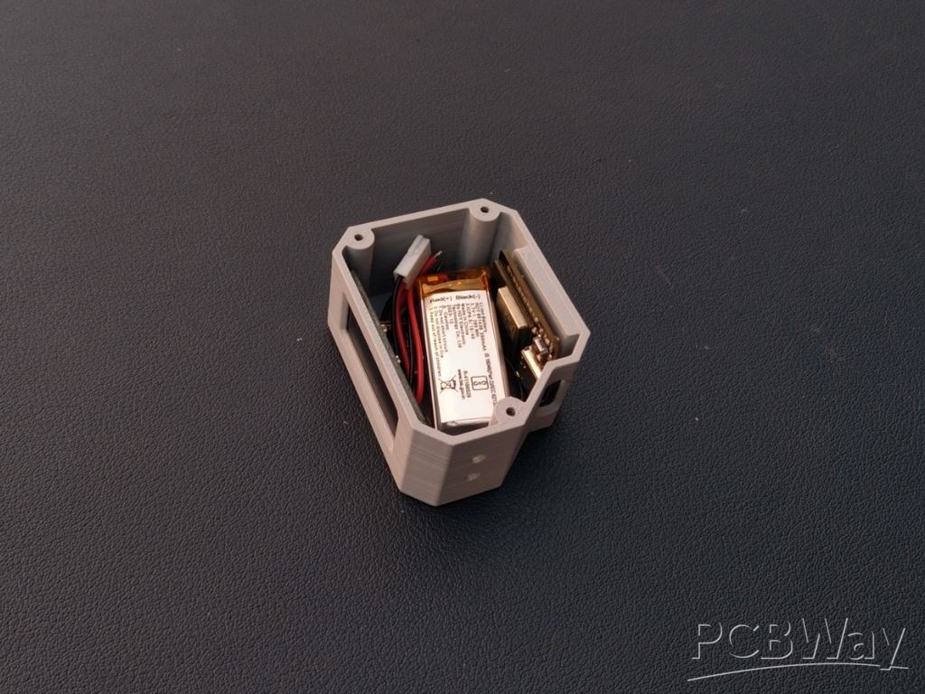 This step is optional — if you want to make your Orbit Clock portable and rechargeable, you can add the Li-Po battery; otherwise, it will also work perfectly when powered via USB. One great feature of the Beetle ESP32-C3 is that it already has a built-in battery charging circuit, so you don’t need any external charging module. Simply connect the battery to the microcontroller following the provided circuit diagram, then place it securely in the empty space inside the enclosure.
Step 6: Connection

It’s time to wire up all the components! Use the provided circuit diagram to make each connection carefully and double-check before powering the circuit. Here are the pin connections:
OLED Display
- OLED Display SCL → Microcontroller SCL
- OLED Display SDA → Microcontroller SDA
- OLED Display VCC → 3V3 of Microcontroller
- OLED Display GND → GND of Microcontroller
Sensor
- SHTC3 Sensor SCL → Microcontroller SCL
- SHTC3 Sensor SDA → Microcontroller SDA
- SHTC3 Sensor VCC → 3V3 of Microcontroller
- SHTC3 Sensor GND → GND of Microcontroller
Battery
- Li-Po Battery → BAT and GND pin of Beetle ESP32-C3
I’m quite comfortable with soldering, so I soldered the wires after assembling all the components in place to make it neat and compact. However, if you’re a beginner, I highly recommend making all the connections before assembly — it will make wiring much easier and reduce the risk of damaging components
Step 7: Cover Assembly
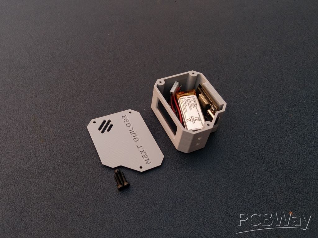
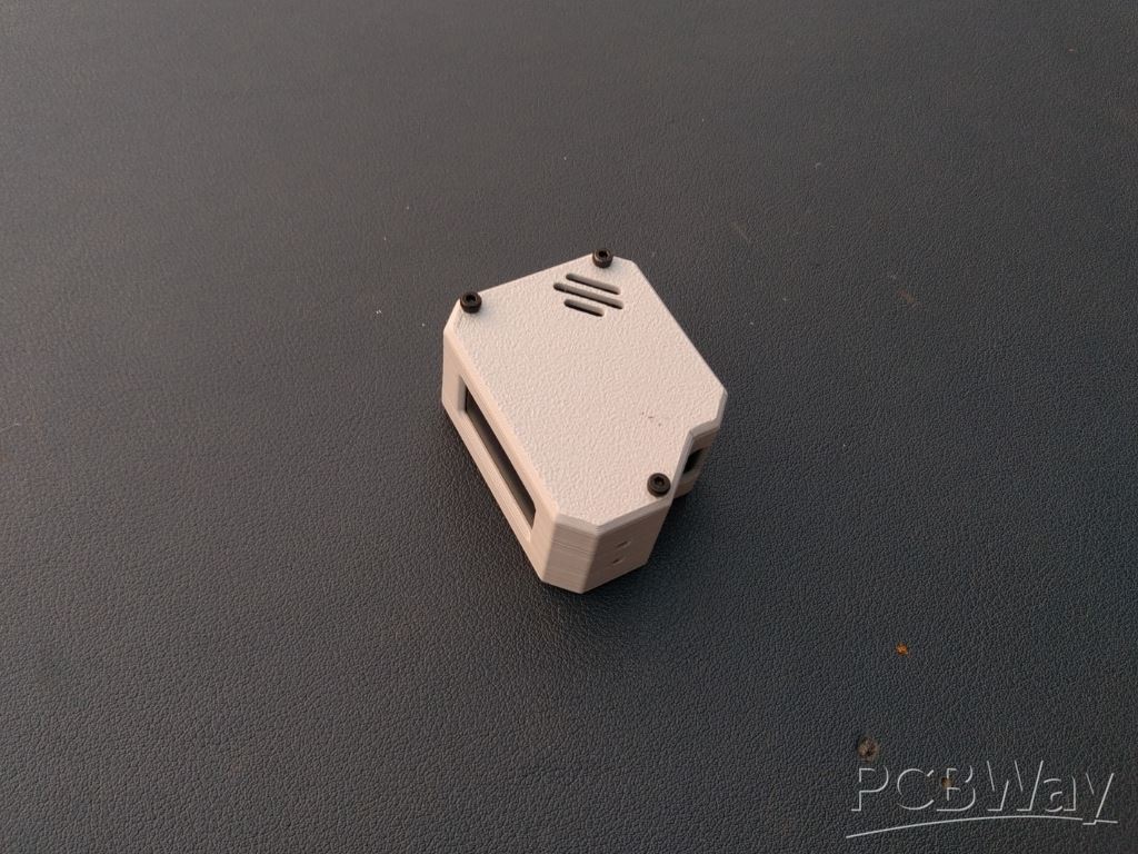 Once all the connections are done and checked properly, it’s time to close the case. Take the 3D-printed cover and carefully align it with the main body of the Orbit Clock. Make sure all sides fit perfectly.
Now, use three small M3 screws to secure the cover in place — this will hold everything tightly and give your mini satellite-style clock a clean, finished look.
Step 8: Legs Assembly

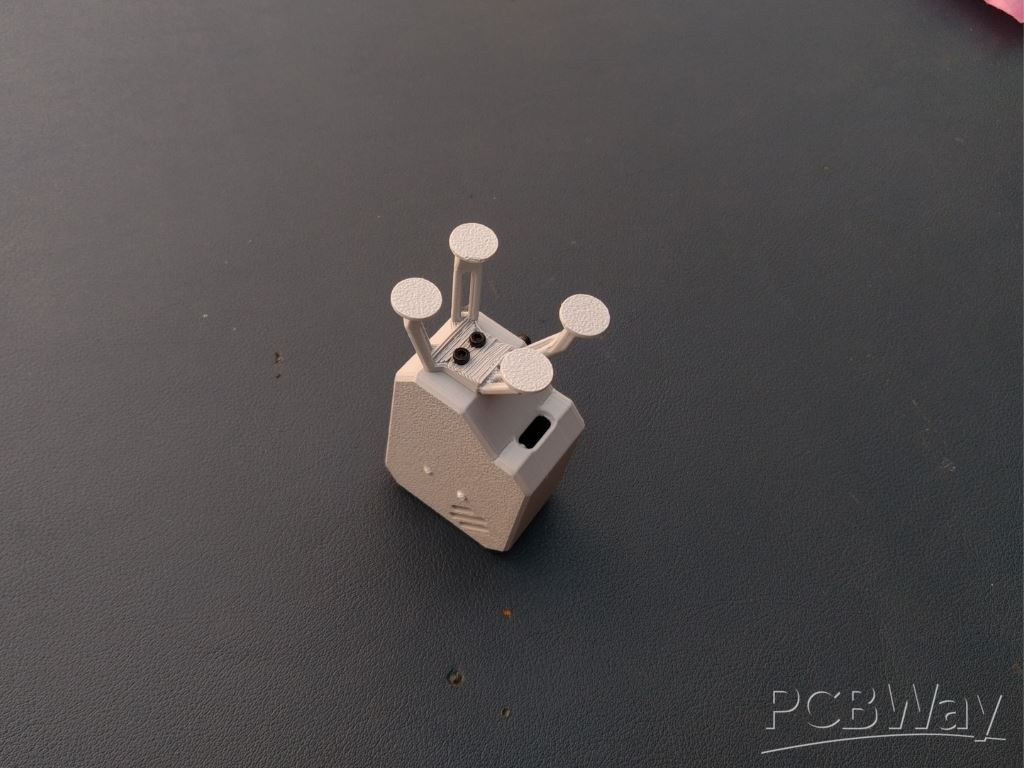
 Once the cover is assembled, it’s time to attach the landing-style legs that give the Orbit Clock its unique satellite look. Take the 3D-printed legs and align them perfectly with their dedicated slots at the bottom of the body.
Use two small M3 screws to fix them securely in place. Make sure legs are tightened evenly so the clock stands straight and stable on any surface.
Step 9: Code Setup
Before getting started, make sure you have the Arduino IDE installed on your computer and the ESP32 board package properly configured. If you haven’t done this yet, check out my previous Instructables project — it includes a complete step-by-step setup guide.
Credit: Inspired by the creative work of Mohit Bhoite. The code structure was referenced from Cumin Lander but completely rewritten for the Orbit Clock project.
Once ready, follow these steps to upload the Orbit Clock code:
- Visit the Orbit Clock GitHub Repository and download the complete project as a ZIP file.
- Extract the ZIP archive to your computer and open the .ino file in the Arduino IDE.
- Install the following required libraries from the Library Manager (Sketch → Include Library → Manage Libraries…):
- NTPClient.h
- Adafruit_GFX.h
- Adafruit_SSD1306.h
- Adafruit_SHTC3.h
Configure Wi-Fi
In the code, locate the section below:
// WiFi credentials const char* ssid = "YOUR_WIFI_SSID"; const char* password = "YOUR_WIFI_PASSWORD";
Replace "YOUR_WIFI_SSID" with your actual Wi-Fi name and "YOUR_WIFI_PASSWORD" with your password.
Configure GMT Offset
The NTPClient library uses a GMT offset in seconds to adjust the time to your local time zone. For that Know your Country GMT offset then Convert GMT offset to seconds & put the value in Code. Example of India (GMT +5:30)
- 5 hours × 3600 = 18000
- 30 min × 60 = 1800
- Total = 19800 sec
In the code, locate this line and change the value according;)
// NTP setup WiFiUDP ntpUDP; NTPClient timeClient(ntpUDP, "pool.ntp.org", 19800, 60000); // IST: UTC+5:30
This ensures your clock shows the time according to your country Standard Time correctly.
Step 10: Uploading Code
Once your code is ready, connect your DFRobot Beetle ESP32-C3 to your computer using a USB cable. In Arduino IDE, make sure to select the correct board and port: go to Tools → Board → ESP32 Boards → DFRobot Beetle ESP32-C3 and Tools → Port → select the COM port your board is connected to. Click Upload in Arduino IDE. The IDE will compile the code and then upload it to your board.
Step 11: Testing

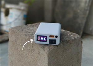
Once the code is uploaded, give your microcontroller 1–2 minutes to connect to your Wi-Fi network. After a successful connection, it will automatically synchronize the current time from the NTP server and start fetching real-time temperature and humidity data from the sensor.
While the USB-C cable is connected, the internal battery will also charge simultaneously, so your Orbit Clock can run both on USB power and battery backup. At this stage, your Orbit Clock is fully functional, charging, and ready for daily use, providing precise time and environmental information in a sleek, compact design.
Conclusion
The OrbitClock brings the charm of space technology to your desk. Its spacecraft-inspired design, glowing OLED display, and real-time temperature and humidity readings make it more than just a clock — it’s a mini space instrument.
With the DFRobot Beetle ESP32-C3, Wi-Fi NTP synchronization ensures precise local time, and the onboard SHTC3 sensor provides accurate environmental data. The USB-C connection keeps the battery charged for uninterrupted operation.
OrbitClock combines smart design, real-time data, and sleek electronics into a functional and visually striking desktop gadget.
Happy Making 🤞🏻
OrbitClock – a Tiny Space-Inspired IoT Environment Clock
*PCBWay community is a sharing platform. We are not responsible for any design issues and parameter issues (board thickness, surface finish, etc.) you choose.


Raspberry Pi 5 7 Inch Touch Screen IPS 1024x600 HD LCD HDMI-compatible Display for RPI 4B 3B+ OPI 5 AIDA64 PC Secondary Screen(Without Speaker)
BUY NOW


- Comments(0)
- Likes(1)
More by Kishan Pratap Singh
-
 A Compact Charging Breakout Board For Waveshare ESP32-C3
The Waveshare ESP32-C3 Mini development board is a powerful and compact solution for modern IoT and ...
A Compact Charging Breakout Board For Waveshare ESP32-C3
The Waveshare ESP32-C3 Mini development board is a powerful and compact solution for modern IoT and ...
-
 World's Smallest 1S Battery Charger
This is a very small 1S lithium battery charger board designed for projects where space is extremely...
World's Smallest 1S Battery Charger
This is a very small 1S lithium battery charger board designed for projects where space is extremely...
-
 DIY Smart Battery Charger
In today's world, batteries are an integral part of our lives, powering everything from our smartpho...
DIY Smart Battery Charger
In today's world, batteries are an integral part of our lives, powering everything from our smartpho...
-
 DIY 3D Printed Keychain Light
Hello Friends, welcome back in my new Instructables. Today I'm going to build my own smallest & ...
DIY 3D Printed Keychain Light
Hello Friends, welcome back in my new Instructables. Today I'm going to build my own smallest & ...
-
 DIY 3D Printed Compact Size Bluetooth speaker
Hello Friends, My self Kishan Pratap Singh. I developed my new project. Kindly let me know your thou...
DIY 3D Printed Compact Size Bluetooth speaker
Hello Friends, My self Kishan Pratap Singh. I developed my new project. Kindly let me know your thou...
-
 200w Mini Smart Inverter PCB
Introducing our Mini Inverter PCB, a compact and efficient solution for portable power needs. This c...
200w Mini Smart Inverter PCB
Introducing our Mini Inverter PCB, a compact and efficient solution for portable power needs. This c...
-
 A Compact Charging Breakout Board For Waveshare ESP32-C3 (V2 – Improved Manufacturability)
The Waveshare ESP32-C3 Mini is an excellent choice for compact IoT projects. However, one limitation...
A Compact Charging Breakout Board For Waveshare ESP32-C3 (V2 – Improved Manufacturability)
The Waveshare ESP32-C3 Mini is an excellent choice for compact IoT projects. However, one limitation...
-
 Custom Coupler for BO Motor to Robot Wheel
Standard robot wheels are widely used in educational and DIY robotic platforms, but they are not alw...
Custom Coupler for BO Motor to Robot Wheel
Standard robot wheels are widely used in educational and DIY robotic platforms, but they are not alw...
-
 Custom Coupler for N20 Gear Motor to Robot Wheel
These rubber wheels are commonly used in small robotic mobile platforms such as 2WD and 4WD robots. ...
Custom Coupler for N20 Gear Motor to Robot Wheel
These rubber wheels are commonly used in small robotic mobile platforms such as 2WD and 4WD robots. ...
-
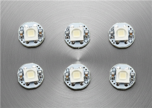 Ultra-Compact RGB Button LED PCB (NeoPixel Compatible)
I designed this tiny RGB button LED PCB to make adding colorful, addressable lighting to projects si...
Ultra-Compact RGB Button LED PCB (NeoPixel Compatible)
I designed this tiny RGB button LED PCB to make adding colorful, addressable lighting to projects si...
-
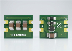 Ultra Compact Boost Converter Module
This project features an ultra-compact, high-efficiency boost converter module designed using the TP...
Ultra Compact Boost Converter Module
This project features an ultra-compact, high-efficiency boost converter module designed using the TP...
-
 PCBWay 11th Anniversary LED Badge – Services Edition 🎉
This project is a custom-designed PCB badge created to celebrate PCBWay’s 11th anniversary and highl...
PCBWay 11th Anniversary LED Badge – Services Edition 🎉
This project is a custom-designed PCB badge created to celebrate PCBWay’s 11th anniversary and highl...
-
 OrbitClock – a Tiny Space-Inspired IoT Environment Clock
Time and space are deeply connected — satellites orbit Earth to keep our clocks synchronized with in...
OrbitClock – a Tiny Space-Inspired IoT Environment Clock
Time and space are deeply connected — satellites orbit Earth to keep our clocks synchronized with in...
-
 DIY Compact UPS for Wifi Router (Easy To Build)
In villages and towns where electricity cut-offs are a daily challenge, one of the first things to g...
DIY Compact UPS for Wifi Router (Easy To Build)
In villages and towns where electricity cut-offs are a daily challenge, one of the first things to g...
-
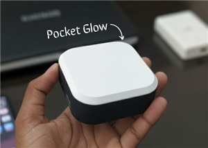 Pocket Glow: a perfect camping light
The call of the wild is always exciting, but it also comes with challenges – like needing the right ...
Pocket Glow: a perfect camping light
The call of the wild is always exciting, but it also comes with challenges – like needing the right ...
-
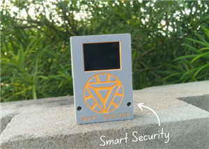 Face Recognition Door Lock with Smartphone Notification
Have you ever wished your home security system felt as futuristic and intelligent as JARVIS from Iro...
Face Recognition Door Lock with Smartphone Notification
Have you ever wished your home security system felt as futuristic and intelligent as JARVIS from Iro...
-
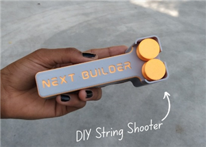 DIY String Shooter
This is my DIY 3D Printed String Shooter—a fun little project I made using two micro dc toy motor. I...
DIY String Shooter
This is my DIY 3D Printed String Shooter—a fun little project I made using two micro dc toy motor. I...
-
 PCBWay 11th Anniversary LED Badge 🎉
This project is a custom-designed PCBWay 11th Anniversary Badge, created to celebrate 11 years of PC...
PCBWay 11th Anniversary LED Badge 🎉
This project is a custom-designed PCBWay 11th Anniversary Badge, created to celebrate 11 years of PC...
-
Programmable Mist Maker - XIAO / QT PY Extension
222 0 0 -
RadioHAT - Raspberry Pi radio development platform
250 0 1 -
-
-
-
-
ARPS-2 – Arduino-Compatible Robot Project Shield for Arduino UNO
2801 0 5 -
A Compact Charging Breakout Board For Waveshare ESP32-C3
3307 3 8 -
AI-driven LoRa & LLM-enabled Kiosk & Food Delivery System
3587 2 2


