


|
|
Raspberry Pi model 4 or 5 |
x 1 | |
|
|
Ultrawide LCD with touch 1600x600 |
x 1 | |
|
|
USB Soundcard |
x 1 | |
|
|
PAM8403 Amplifier module |
x 1 |

|
Soldering Iron Kit |
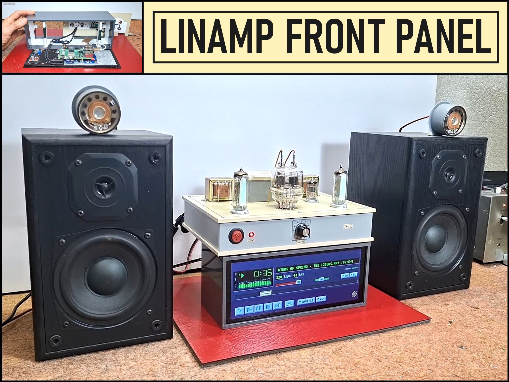
LINAMP Project – Winamp-Style Audio Front Panel on Raspberry Pi 5
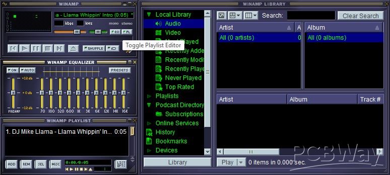
Winamp is one of the most iconic and historically significant digital media players ever created. It became synonymous with the MP3 revolution and the early days of digital music ownership. It supported a wide array of audio formats, including MP3, AAC, WAV, and WMA. You're probably familiar with its classic style: a simple, small interface that resembled a car stereo head unit, complete with a separate equalizer and playlist window.
Recently the source code of this player was released on GitHub. After that, many enthusiasts created versions of this legendary player for multiple operating systems. Incredibly intuitive is the idea of Rodrigo Méndez to create a practical "Front Panel" for an Audio Amplifier in the style of such devices from the end of the last century, based on this player. In addition to its beautiful appearance, this front panel is also very functional. The original device is based on a 7.9-inch ultrawide HDMI touch display with a resolution of 1280x480 and a Raspberry Pi small single board computer. I currently have an ultrawide LCD with a built-in Raspberry Pi 5 intended for a POS system project, so I decided to use this existing hardware.
The difference with the original project is in the resolution and dimensions of the display, namely my display is 9.3 inches, and has a native resolution of 1600x600 pixels. My knowledge of Raspberry Pi OS is quite limited, so I had to spend more time searching for information on the Internet. Therefore, the explanation and terminology for the procedure for implementing this project will be at the lowest level, which would be a great advantage for absolute beginners.
This project is sponsored by PCBWay . From concept to production, PCBWay provide cutting-edge electronic design solutions for global innovators, Including hardware design, software development, mechanical design, product testing and certification. PCBWay engineering team consists of experienced engineers in electronics, embedded systems, and product development. They successfully delivered hundreds of projects across industries such as medical devices, industrial automation, consumer electronics, smart home, and IoT.

The following is a sequential presentation of each part.
- First, on the Windows PC, we need to create an image of the Raspberry Pi operating system on an SD card. For this purpose, we need an SD card with a capacity of 8GB or larger.
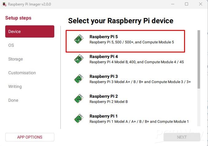
Then we need to download the Raspberry Pi imager software from the given Link . Now we need to select the Raspberry Pi model (in my case, Raspberry Pi 5).
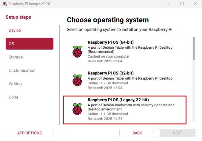
Next is the operating system, we select "Port of Debian Bookworm" according to the author's recommendations.
Then we select the storage device and customization, which I will skip in this case. Now we put the prepared SD card in the Raspberry Pi and start it. At first, I will use a large monitor, mouse and keyboard for easier work and visibility. We also need to enable internet access via network cable or WiFi. When the operating system boots up, open the author's GitHub page in a browser where the installation is explained in detail.
First, we need to clone the project from GitHub to the local storage with the following command
(command for cloning the project: git clone https://github.com/Rodmg/linamp.git).
Now a folder named "linamp" should appear in the File Explorer.
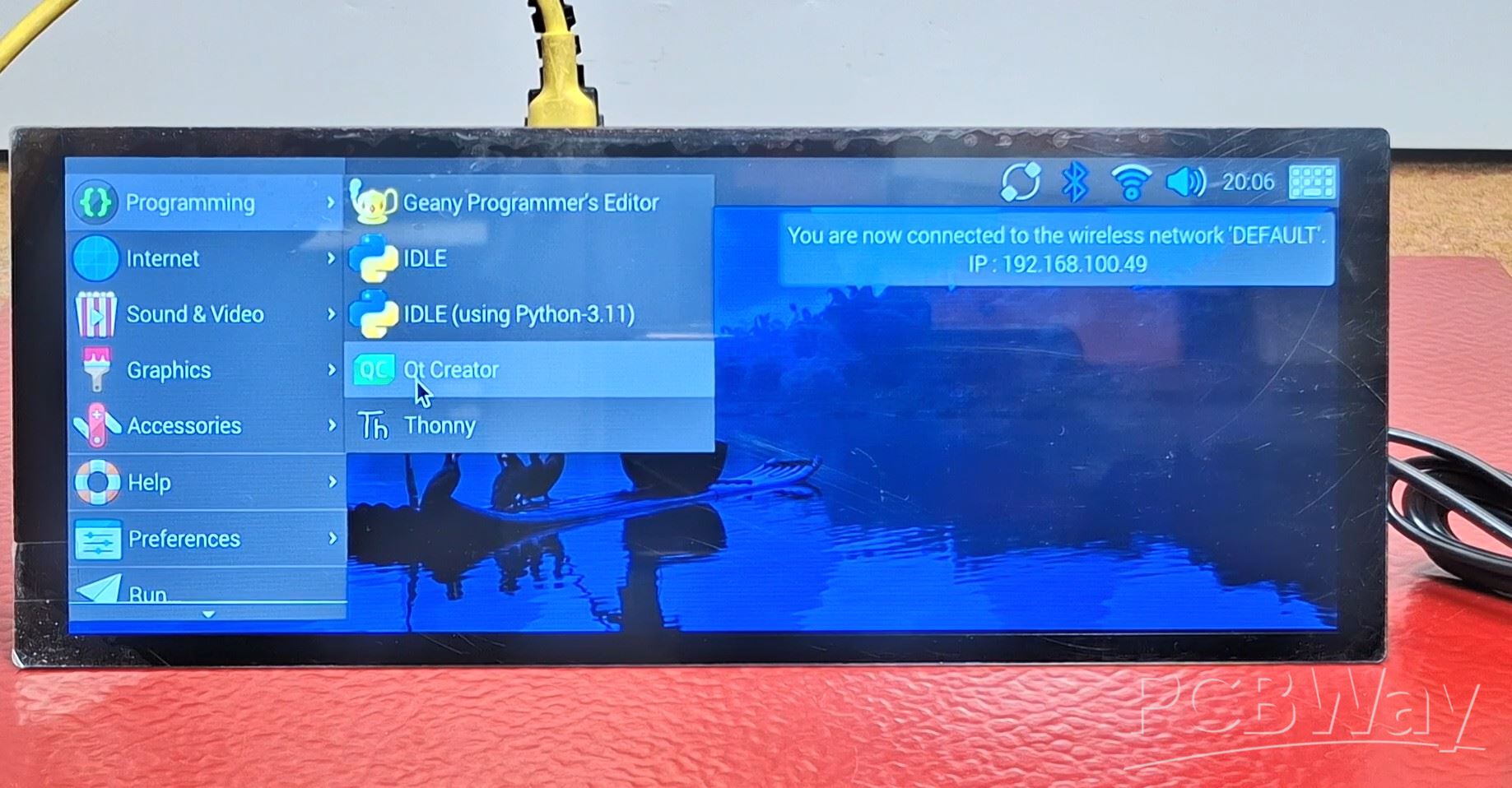
Next, we need to open the Terminal window and enter that folder with "cd linamp" - Enter. Then we copy the instructions from Github into the Terminal and press Enter. Now the installation of support (libraries and environment) as well as the program itself is being performed. This will take a few minutes. Then we go to "Programing" and we will see that new programs have been installed, Python 3.11 and QT Creator.
We start QT Creator, Open Project, Linamp folder, and activate the file named: CMakelists.txt. Now we go RUN, and after a certain time the program will start. If the Linamp program appears, it means that we have successfully installed it.
As you can see from the above, the installation is extremely simple. However, if you try to install it on another version of the OS, such as the latest OS (for example, a port of Debian Trixie), you will notice that it is almost impossible due to certain incompatibilities of the libraries and the environment.
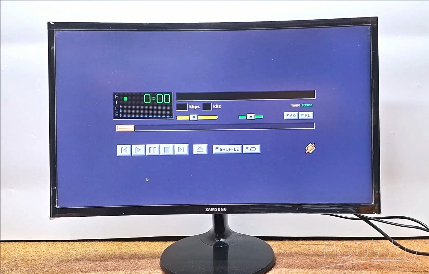
Now it's time to connect the original touch display. We start the program in the same way as before. As you can see, Linamp does not cover the entire screen and there is empty space on a
The reason for this is the fact that the author created the program strictly for a resolution of 1280x400, and specifically on this display it is 1600x600. It is very simple to set the required resolution on this display. We go to preferences - screen configuration, right click on HDMI - resolution. However, the required resolution is not here. In order for the required resolution to appear, we need to make certain changes to the OS kernel. For this purpose, the following procedure is used:
In the terminal window, we write the following command:
(sudo nano /boot/firmware/cmdline.txt) - Enter
Now before the beginning of the line we write:
(video=HDMI-A-1:1280x480@60D) and leave one space
Next:
Press Ctrl+O to write out the file.
Press Enter to confirm the file name.
Press Ctrl+X to exit nano.
Reboot your Raspberry Pi to apply the change:
(sudo reboot)
After restarting, the display menu should have the required resolution.
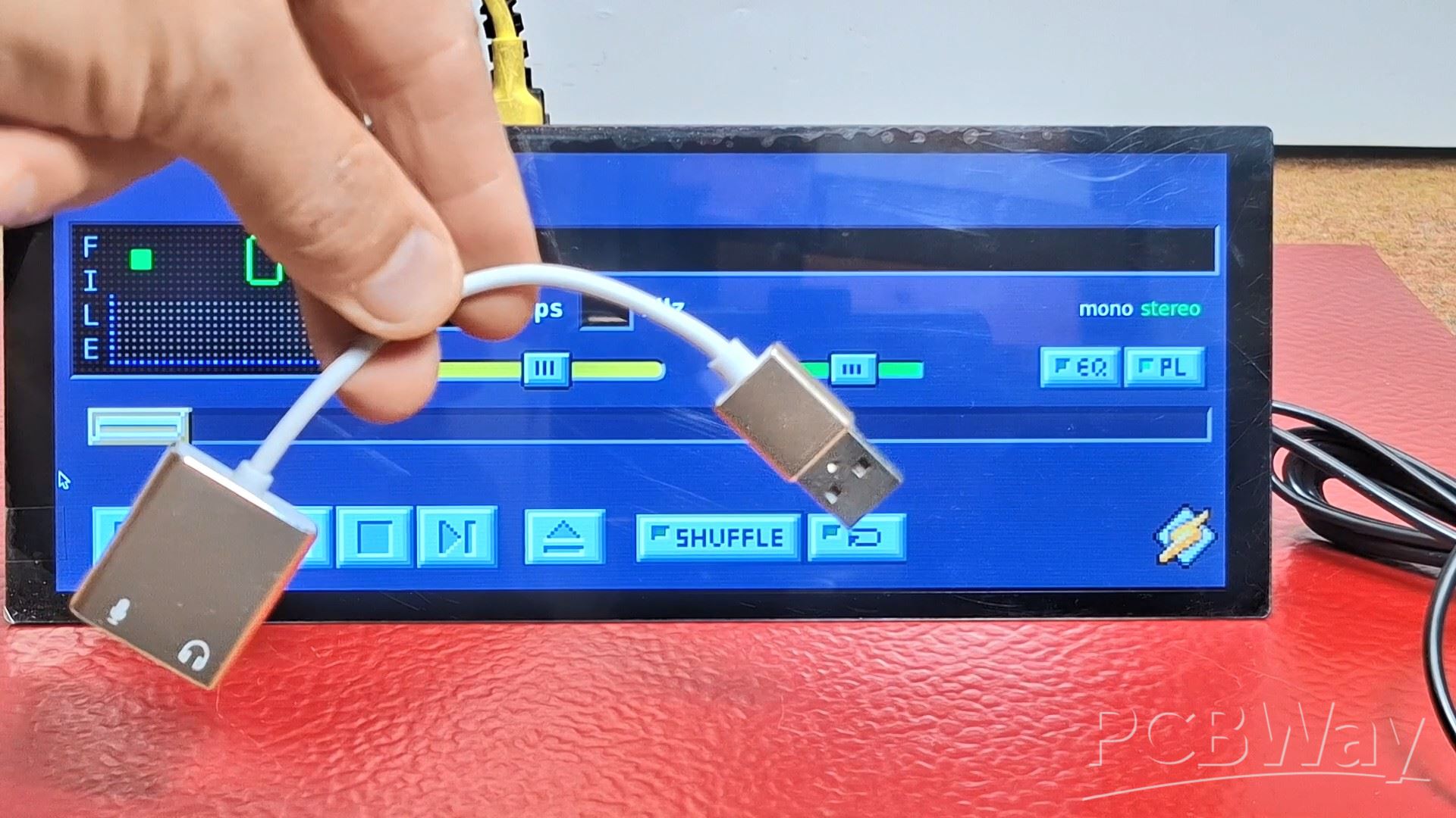
One very important note: Raspberry Pi 5 does not have a standard audio port, but the sound goes through the HDMI protocol. This means in practice that this program will crash on startup unless there is a standard audio device. For this purpose, I installed this small cheap USB audio accessory (sound card).
After assembling and testing the device, I had a very unpleasant experience. Namely, out of carelessness, I mistakenly connected 12V instead of 5V and at that moment I smelled the smell of burnt electronic components. Raspberry Pi 5 was irreversibly damaged. On the display, I discovered a small SOT23-6 chip marked "LPS FtEf1" which was completely shorted and at the same time I could not find any information about it anywhere.
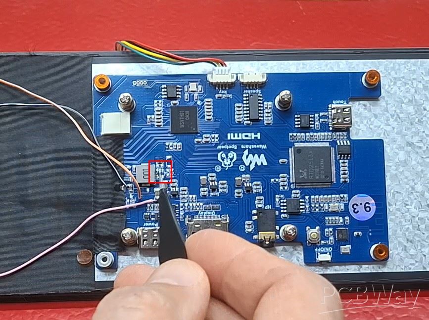
According to the components around it, it was almost clear that it was a BOOST chip that raises the voltage from 5V to the appropriate level to power the LED backlight. So, in place of the cathode of the Schottky diode from the boost converter circuit, I connected 20V with a limited current of 10mA. The backlight appeared with a very weak intensity and flickering. Then I gradually increased the limited current to 60mA and got a completely normal LED backlight on the Display.
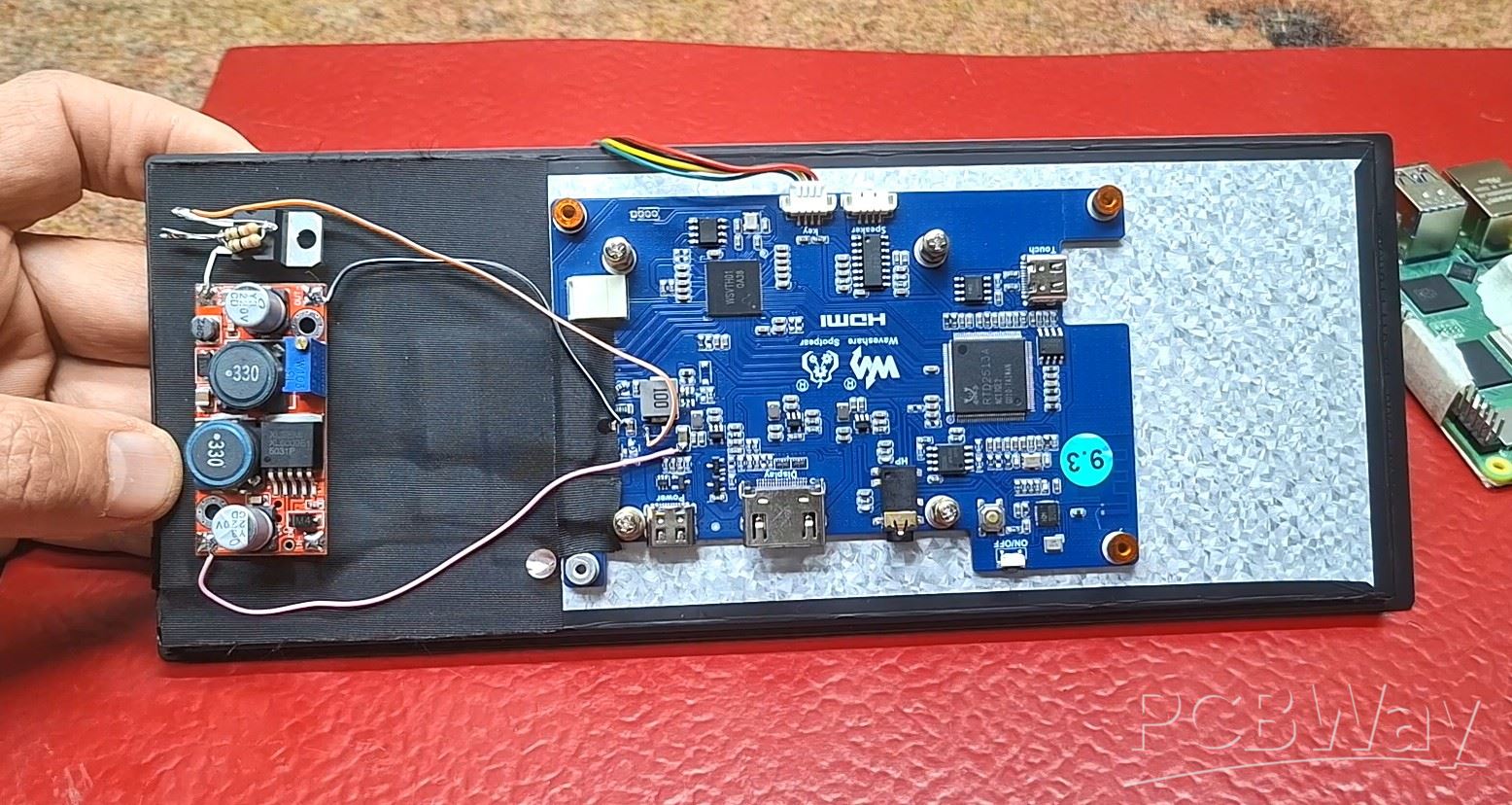
Then, as a more elegant solution, I connected a cheap external BOOST converter module from 5 to 20V and with an LM317 I limited the output current to exactly 60mA. This way I got the display back fully functional (otherwise its price is around 100 Dollars.)
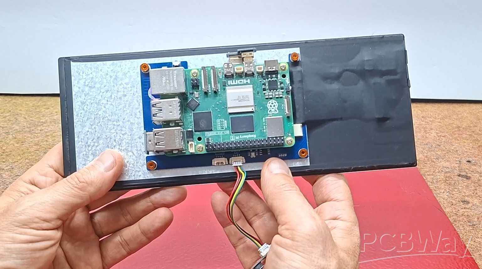
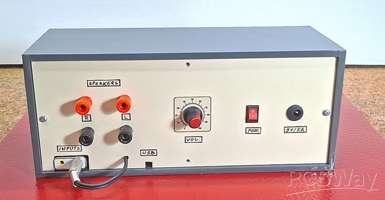
Now it's time to install the device in a suitable box and demonstrate its functionality. For this purpose, I made the box from PVC material and covered it with colored self-adhesive wallpaper. This is what the finished product looks like. Inside is the Raspberry Pi 5 plus the HDMI touch display module, and on the back panel is a small stereo amplifier module PAM8403, but of course a more powerful amplifier can be installed.
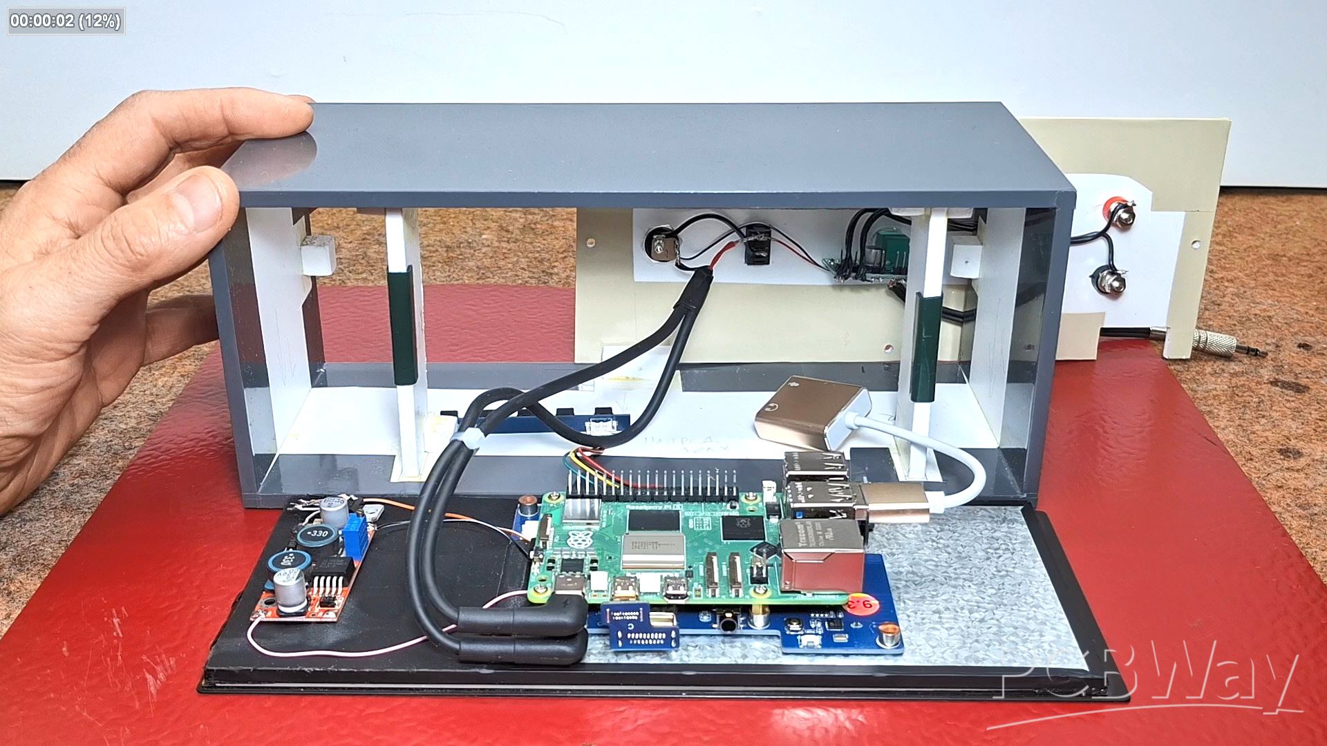
It have the 5V / 5A input voltage connector as well as a small toggle switch. The volume potentiometer is part of the amplifier module. As I mentioned earlier, for the software to work on the Raspberry Pi 5, you need to add an external USB sound card with appropriate input and output connectors. Its output is connected to the input of the audio amplifier.
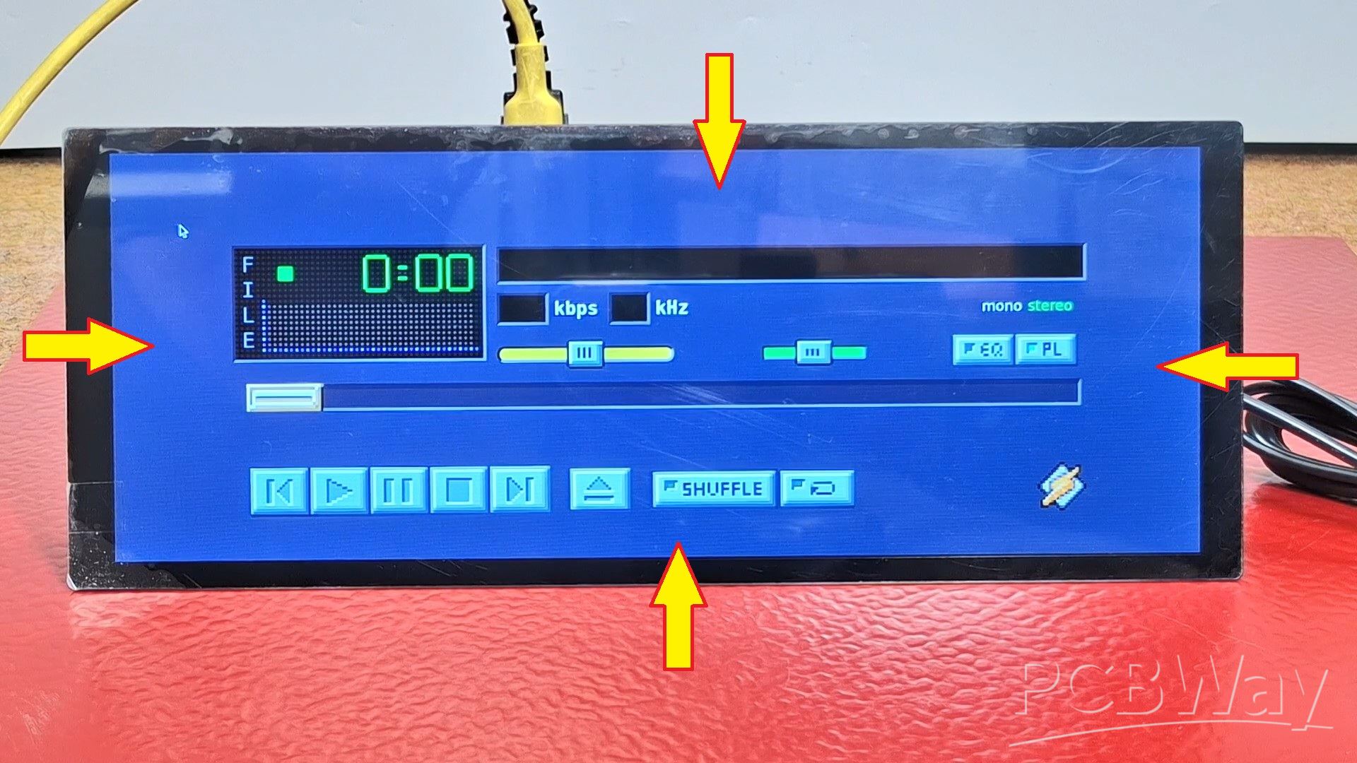
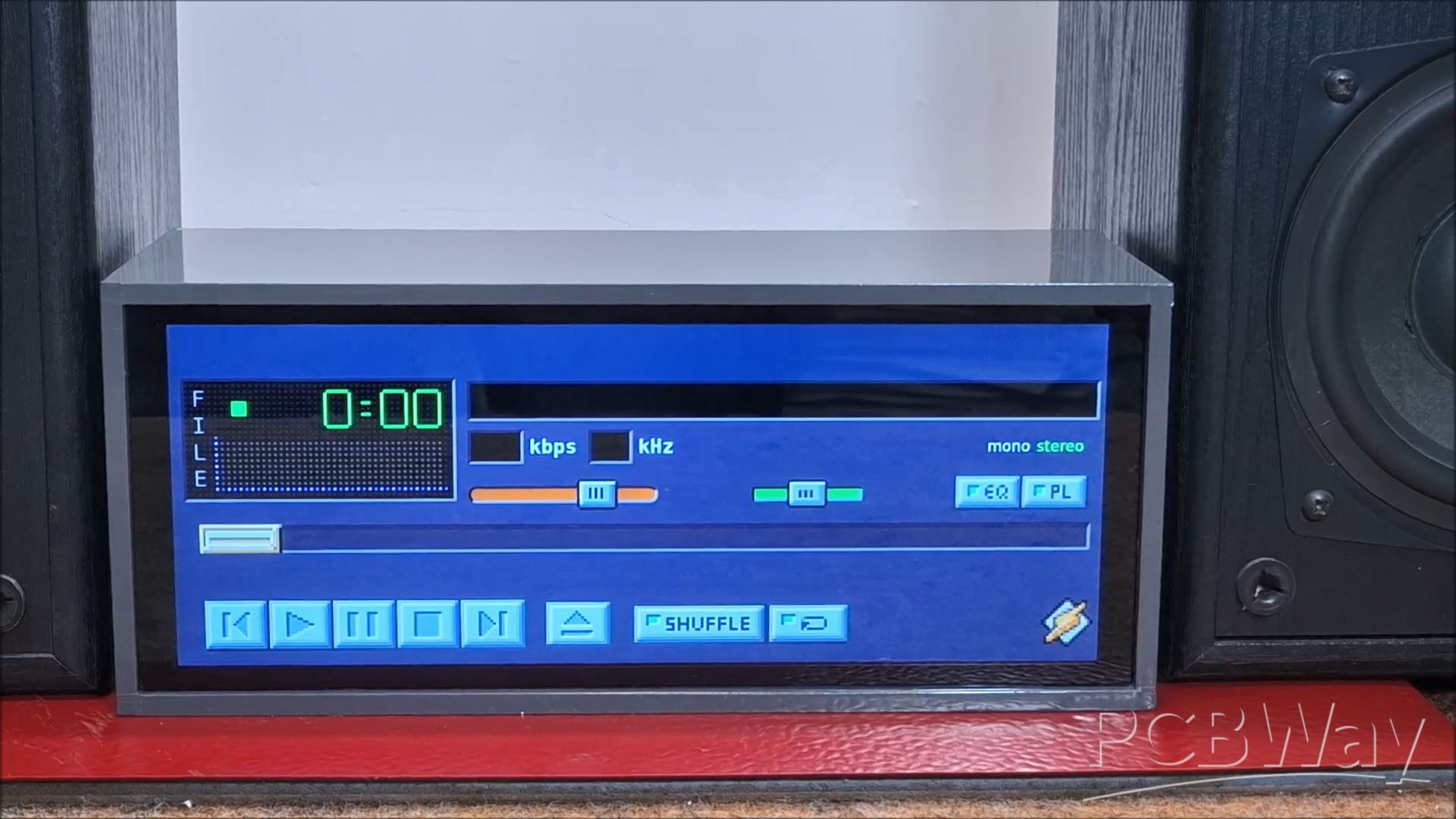
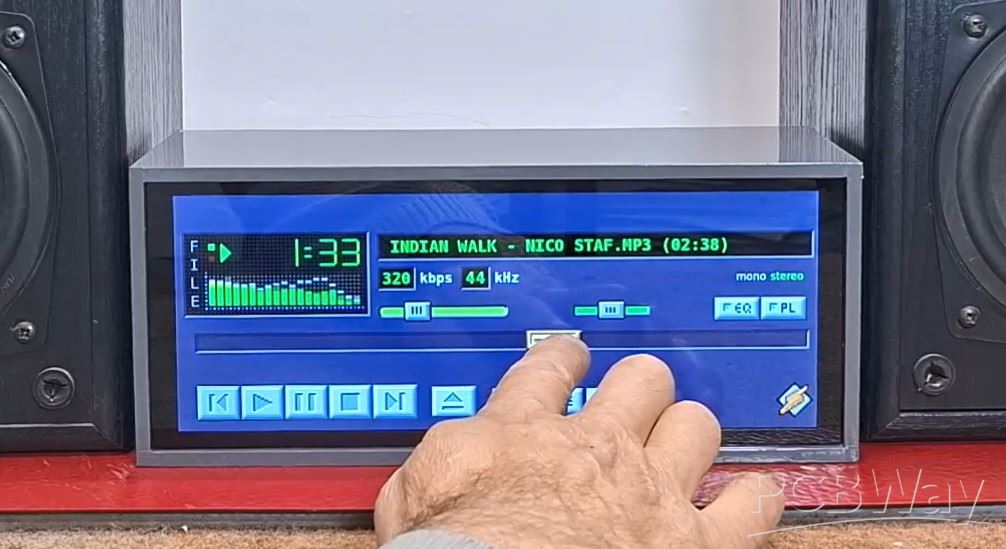
I start the device with the small switch on the back and wait for the operating system to boot. It is very easy to adjust the option for the program to start automatically, but I left that part out so that I can gradually show you how to turn it on. It is easier to go to the LiNAMP folder and start the shell script there directly. This is what the active audio amplifier looks like with the Winamp interface.
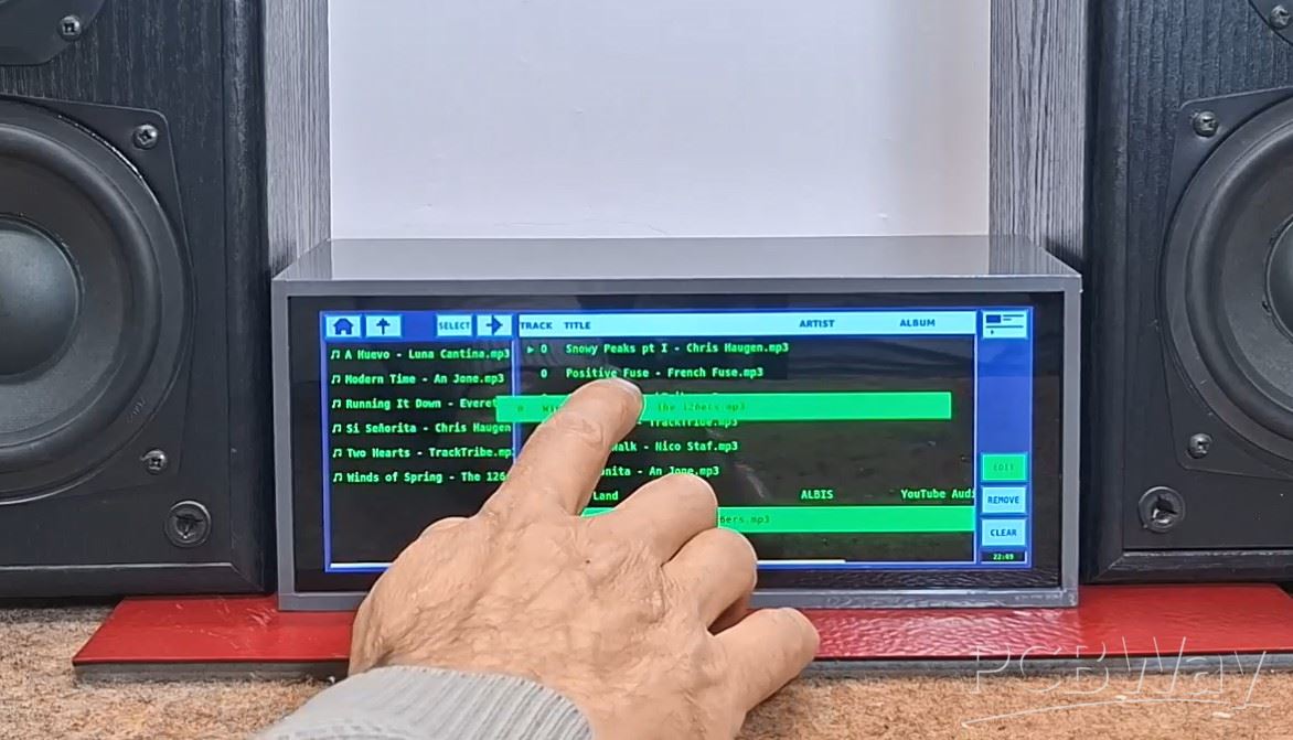
All buttons, the slider, the volume and balance potentiometer, are responsive to touch. I connected two sound boxes to the output of the audio amplifier. The playlist button opens a window for sorting the playlist, just like in the original software. We need to select the folder with music and we can edit the playlist with drag and drop.
When playing a song, the equalizer is active, and the long slider shows the duration and elapsed time of the song. Just like in the original, with this slider we can select the moment until which the song is activated.
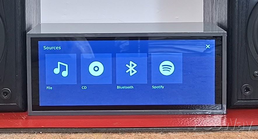
As I mentioned earlier, all other functions are activated by touching the screen. By pressing the Winamp logo, we enter a menu where we can select one of four sources from which the sound would be emitted: File (that is this particular case), external USB CD player, Bluetooth source, or Spotify.
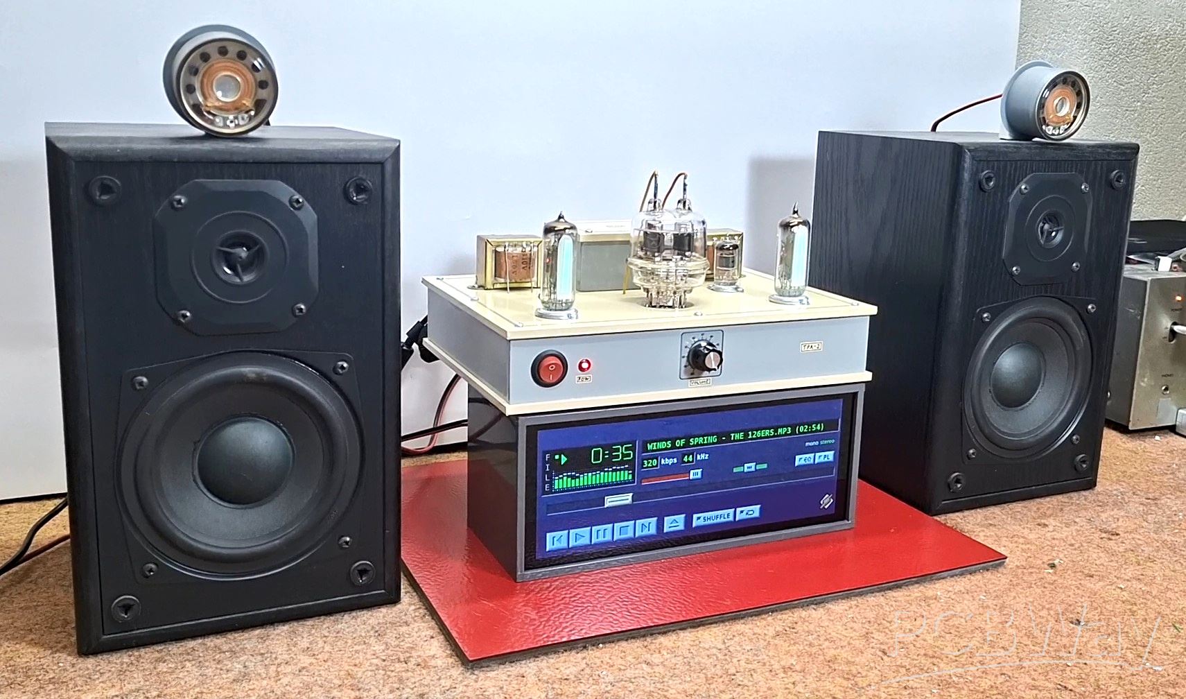
Now I will present you with a special case where I will use a Stereo Tube amplifier at the output, as a symbiosis between very old and the latest technology.
And finally a short conclusion. This project perfectly fuses the iconic Winamp software with modern Raspberry Pi functionality, where every original Winamp function is fully touch-responsive on the finished product, demonstrating a successful and practical tribute to a legendary media player.
Link to the original project where you can also get a pre-installed SD card and 3D print files: https://store.linamp.org/
LINAMP Project – Winamp-Style Audio Front Panel on Raspberry Pi 5


Raspberry Pi 5 7 Inch Touch Screen IPS 1024x600 HD LCD HDMI-compatible Display for RPI 4B 3B+ OPI 5 AIDA64 PC Secondary Screen(Without Speaker)
BUY NOW


- Comments(1)
- Likes(1)
More by Mirko Pavleski
-
 Arduino 3D Printed self Balancing Cube
Self-balancing devices are electronic devices that use sensors and motors to keep themselves balanc...
Arduino 3D Printed self Balancing Cube
Self-balancing devices are electronic devices that use sensors and motors to keep themselves balanc...
-
 ESP32-C3 Color Detector with TCS34725, Real-Time RGB Detection & Web Interface
Color detection is a fundamental task in many embedded systems – from industrial sorting machines t...
ESP32-C3 Color Detector with TCS34725, Real-Time RGB Detection & Web Interface
Color detection is a fundamental task in many embedded systems – from industrial sorting machines t...
-
 DIY ESP32 Telegram Flood Protection System - Smart Home Automation
Recently I had an unpleasant experience in my home, specifically my ground floor was flooded as a r...
DIY ESP32 Telegram Flood Protection System - Smart Home Automation
Recently I had an unpleasant experience in my home, specifically my ground floor was flooded as a r...
-
 Real-Time Air Traffic Radar using ESP32 + ADS-B Data
ADS-B, which stands for Automatic Dependent Surveillance-Broadcast, is the modern standard for trac...
Real-Time Air Traffic Radar using ESP32 + ADS-B Data
ADS-B, which stands for Automatic Dependent Surveillance-Broadcast, is the modern standard for trac...
-
 DIY Green Laser Night Sky Object Finder - Find Stars & Galaxies Instantly with great accuracy
As an amateur astronomer, especially at the beginning, the most difficult part of observing the nig...
DIY Green Laser Night Sky Object Finder - Find Stars & Galaxies Instantly with great accuracy
As an amateur astronomer, especially at the beginning, the most difficult part of observing the nig...
-
 DIY Avionics Simulator with ESP32 - Artificial Horizon, Compass & Altimeter
The inspiration for this project comes from classical aircraft cockpit instruments used for navigat...
DIY Avionics Simulator with ESP32 - Artificial Horizon, Compass & Altimeter
The inspiration for this project comes from classical aircraft cockpit instruments used for navigat...
-
 DIY Miniature X-Ray Machine using a TV Vacuum Tube DY86
An X-ray machine (or radiograph) is a quick, painless medical test that produces images of the struc...
DIY Miniature X-Ray Machine using a TV Vacuum Tube DY86
An X-ray machine (or radiograph) is a quick, painless medical test that produces images of the struc...
-
 Simple SDR Receiver Using 2x NE612 - Dual Conversion, Superheterodyne (0.1–30 MHz)
SDR (Software Defined Radio) is a radio system in which most of the functions of a classic radio (f...
Simple SDR Receiver Using 2x NE612 - Dual Conversion, Superheterodyne (0.1–30 MHz)
SDR (Software Defined Radio) is a radio system in which most of the functions of a classic radio (f...
-
 DIY Vintage TV VU Meter with peak indicators
Some time ago in one of my projects I presented you a way to turn a black and white old mini TV int...
DIY Vintage TV VU Meter with peak indicators
Some time ago in one of my projects I presented you a way to turn a black and white old mini TV int...
-
 DIY Tesla Coil based Plasma Rife Machine
In several of my previous videos, I presented you with different ways to make a Rife Machine, from ...
DIY Tesla Coil based Plasma Rife Machine
In several of my previous videos, I presented you with different ways to make a Rife Machine, from ...
-
 ESP32 Analog VU Meter – Smooth Needle, Real Audio Response (DIY Build)
In several of my previous videos I have shown you how to make analog VU meters emulated on differen...
ESP32 Analog VU Meter – Smooth Needle, Real Audio Response (DIY Build)
In several of my previous videos I have shown you how to make analog VU meters emulated on differen...
-
 The Ultimate Smartphone VFO ESP32 & Si5351 Wireless Control
Variable frequency oscillators (VFOs) are commonly used in radio transmitters and receivers, especi...
The Ultimate Smartphone VFO ESP32 & Si5351 Wireless Control
Variable frequency oscillators (VFOs) are commonly used in radio transmitters and receivers, especi...
-
 DIY Shortwave Propagation Monitor - Measure Ionosphere Conditions
Shortwave Propagation is the way radio waves in the 3 to 30 MHz range travel from point A to point ...
DIY Shortwave Propagation Monitor - Measure Ionosphere Conditions
Shortwave Propagation is the way radio waves in the 3 to 30 MHz range travel from point A to point ...
-
 Professional grade Smart Lock with ESP32, BLE and Android App Control
An electronic codelock is a security device that grants access using a numerical sequence—a PIN cod...
Professional grade Smart Lock with ESP32, BLE and Android App Control
An electronic codelock is a security device that grants access using a numerical sequence—a PIN cod...
-
 Building a 3-Input Stereo ECC83 (12AX7) Tube Preamp
Some time ago I presented you a project for a 3W stereo tube amplifier with a GU32 output vacuum t...
Building a 3-Input Stereo ECC83 (12AX7) Tube Preamp
Some time ago I presented you a project for a 3W stereo tube amplifier with a GU32 output vacuum t...
-
 ESP32 Weather Dashboard with Satellite Maps and 16-day Weather Forecast
As you can see from my previous videos, besides Electronics, my fields of experimentation and proje...
ESP32 Weather Dashboard with Satellite Maps and 16-day Weather Forecast
As you can see from my previous videos, besides Electronics, my fields of experimentation and proje...
-
 Retro Analog VU Meter on Round dispalys (ESP32 and GC9A01)
Recently, in one of my previous videos I presented you a Retro VU Meter project on round displays ...
Retro Analog VU Meter on Round dispalys (ESP32 and GC9A01)
Recently, in one of my previous videos I presented you a Retro VU Meter project on round displays ...
-
 Ultimate 2-Player Reaction Timer with WS2812B LED Strips & Arduino
Arcade reaction game is a genre of play designed to test a player's physical response time and hand...
Ultimate 2-Player Reaction Timer with WS2812B LED Strips & Arduino
Arcade reaction game is a genre of play designed to test a player's physical response time and hand...
-
Programmable Mist Maker - XIAO / QT PY Extension
952 1 0 -
RadioHAT - Raspberry Pi radio development platform
772 0 2 -
-
-
-
-
ARPS-2 – Arduino-Compatible Robot Project Shield for Arduino UNO
3230 0 6 -
A Compact Charging Breakout Board For Waveshare ESP32-C3
3857 3 8 -
AI-driven LoRa & LLM-enabled Kiosk & Food Delivery System
4208 2 2


