


|
|
Old CRT B&W TV |
x 1 | |
|
|
Arduino Nano R3 |
x 1 | |
|
|
Maxim Integrated DS3231M - ±5ppm, I2C Real-Time Clock |
x 1 | |
|
|
Resistor 1k ohm |
x 1 | |
|
|
Resistor 4.75k ohm |
x 1 |

|
Soldering Iron Kit |
|

|
arduino IDEArduino
|
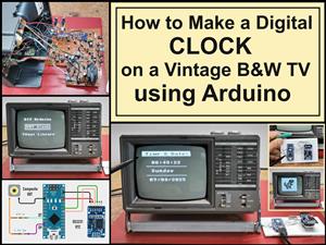
How to Make a Digital Clock on a Vintage B&W TV using Arduino
These days I accidentally came across this small retro Black and White TV with a built-in Radio, so I immediately decided to make some simple useful device with it. Of course, first I decided to check its current condition and functionality.
Let's examine the Radio receiver. As far as I can see, this part of the device is functioning normally and the only thing that needs to be cleaned is the volume potentiometer, possibly with some contactor spray.
Now let's move on to the TV receiver. In a few seconds, a white raster appears on the screen, which is a sign that this part of the device is probably completely functional. We still have to examine the tuner part, by bringing an analog signal to the antenna input. For this purpose, I will use the signal from cable television. This signal is in the VHF-III Band, so now I will start searching for channels.
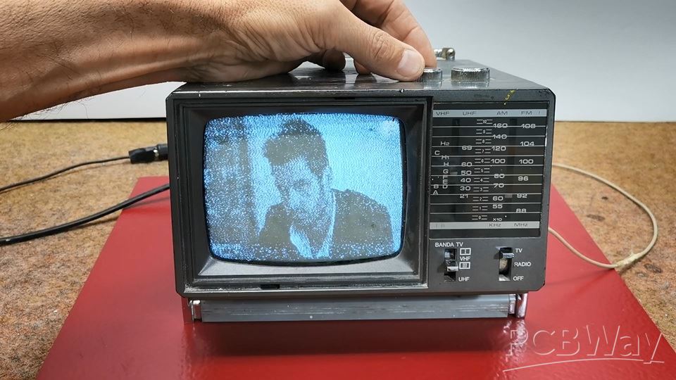
As I assumed, and the TV receiver is completely functional, but unfortunately nowadays it has no significant use value except as part of some retro TV collection.
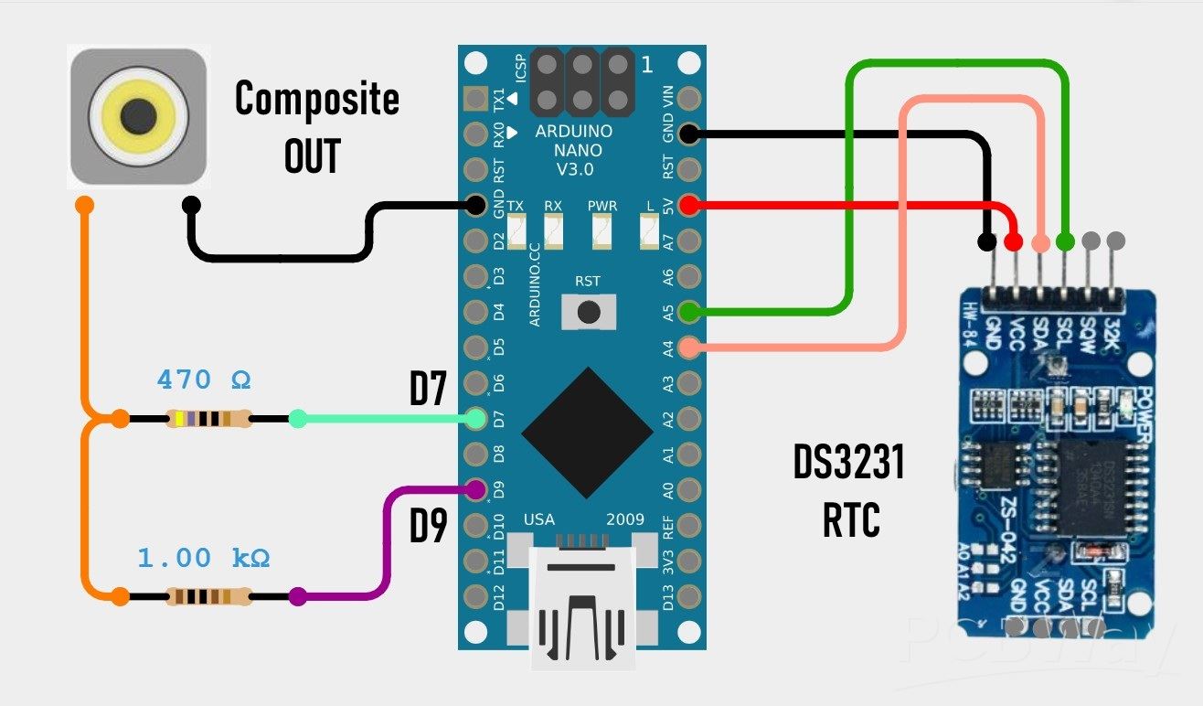
I got the idea to "bring back to life" this small cute device in a way that I would make some kind of clock that would display the time and date on the screen. And of course the most suitable for that purpose is the Arduino microcontroller together with the TVout library with the help of which a composite signal is generated through only two resistors.
The model of this device is "Inno-Hit TV128" but after a long search I was unable to find any service manual or circuit diagram. Many years ago I worked in a TV repair shop and I have relatively extensive knowledge in this area.
This project is sponsored by PCBWay . From September 1st 2025 to 31st Januarry 2026 PCBWay organize the 8th Priject Design Contest. All interested participants can compete in three categories: Electronic Project, Mechanical Project or AIoT Project. The best projects will receive valuable prizes in cash, value cupons and developement boards. Don't miss this unique opportunity and submit your project as soon as possible. PCBWay has all the services you need to create the project at the Best price.

By definition the composite input should be located somewhere between the video amplifier and the sync section. After a detailed examination of the PCB and its components I discovered that the video amplifier in this case is TA7678AP IC and the sync section is µPC1379C IC.

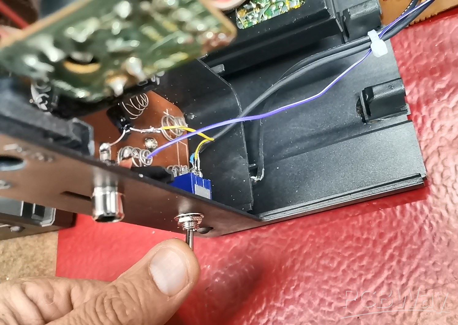
After several hours of experimentation I discovered that the composite input is located right after the video output from TA7678AP IC. That video signal passes through this jumper J112.
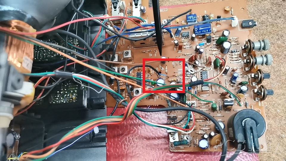
So I need to remove this jumper so that the previous tuner circuit does not affect the signal, and connect the composite input directly to the input of the sync section.
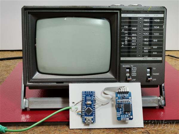
Composite signal generator consisting of an Arduino Nano and 2 resistors, and there is also the DS3231 real time clock module with a built-in battery from which the exact time is read and displayed on the TV screen.
Now for testing I will send a demo signal, actually an example from the TVout library. One important note. If you install the TVout library by default via "manage libraries" or by copying it to the library folder, you will get the error "fontALL.h: No such file or directory" when compiling.
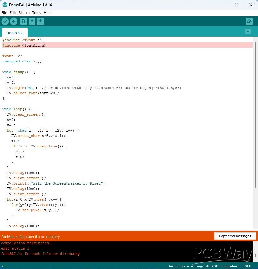
To avoid this, we need to install the two libraries "TVout" and "TVoutfonts" separately, which are given at the end of the text.
Now let's start testing. We bring the composite signal generated by the Arduino to the appropriate input which is connected in the manner explained previously. The switch should be in the "Composite" position. The content is clearly displayed on the screen.
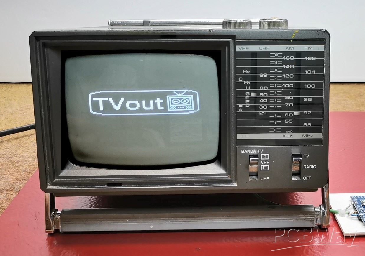
Understandably, now the BAND switch has no function because the tuner section has been omitted. Now you can adjust the brightness and contrast of the image and, if necessary, horizontal or vertical synchronization. And as I mentioned earlier, I created a relatively simple code that will display the time, day of the week and date in digital form. Initially, my idea was an analog clock but due to the extremely low resolution that can be generated by the Arduino, the image was desperately bad.
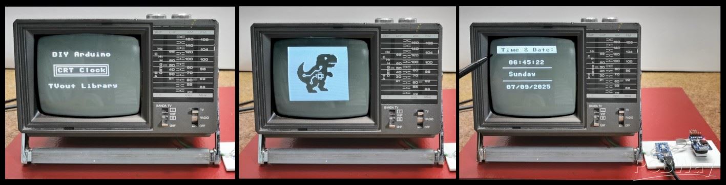
The code is mainly based on the TVout library so my goal was to introduce several different possibilities such as drawing Logos, rectangles, lines, text borders, as well as black text on a white background.
The exact time and date are read from the DS3231 Realtime Clock module which also has a built-in battery to save time when there is no power.
Otherwise, when modifying the TV, I installed a small switch that allows you to choose between standard TV mode and composite video mode.
And finally, a short conclusion. This project successfully transforms a vintage TV into a functional and stylish retro clock. It's a perfect fusion of classic hardware and modern microcontroller simplicity. Also, modifying the small TV without any documentation or schematics was a big challenge for me.
How to Make a Digital Clock on a Vintage B&W TV using Arduino


Raspberry Pi 5 7 Inch Touch Screen IPS 1024x600 HD LCD HDMI-compatible Display for RPI 4B 3B+ OPI 5 AIDA64 PC Secondary Screen(Without Speaker)
BUY NOW


- Comments(1)
- Likes(0)
More by Mirko Pavleski
-
 Arduino 3D Printed self Balancing Cube
Self-balancing devices are electronic devices that use sensors and motors to keep themselves balanc...
Arduino 3D Printed self Balancing Cube
Self-balancing devices are electronic devices that use sensors and motors to keep themselves balanc...
-
 Retro Analog VU Meter on Round dispalys (ESP32 and GC9A01)
Recently, in one of my previous videos I presented you a Retro VU Meter project on round displays ...
Retro Analog VU Meter on Round dispalys (ESP32 and GC9A01)
Recently, in one of my previous videos I presented you a Retro VU Meter project on round displays ...
-
 Ultimate 2-Player Reaction Timer with WS2812B LED Strips & Arduino
Arcade reaction game is a genre of play designed to test a player's physical response time and hand...
Ultimate 2-Player Reaction Timer with WS2812B LED Strips & Arduino
Arcade reaction game is a genre of play designed to test a player's physical response time and hand...
-
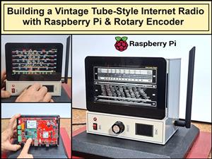 Building a Vintage Tube-Style Internet Radio with Raspberry Pi & Rotary Encoder
Internet radio (also known as web radio or net radio) is a digital audio service transmitted via th...
Building a Vintage Tube-Style Internet Radio with Raspberry Pi & Rotary Encoder
Internet radio (also known as web radio or net radio) is a digital audio service transmitted via th...
-
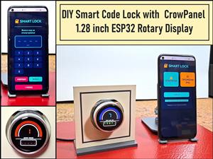 DIY Smart Code Lock with CrowPanel 1.28 ESP32 Rotary Display
A code lock is a keyless security device—either mechanical or electronic—that restricts access to d...
DIY Smart Code Lock with CrowPanel 1.28 ESP32 Rotary Display
A code lock is a keyless security device—either mechanical or electronic—that restricts access to d...
-
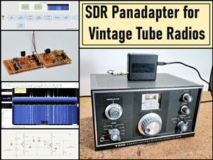 SDR Panadapter for Vintage Tube Radios – Step-by-Step Tutorial
A radio panadapter (or panoramic adapter) is a device or software tool used in amateur radio and ot...
SDR Panadapter for Vintage Tube Radios – Step-by-Step Tutorial
A radio panadapter (or panoramic adapter) is a device or software tool used in amateur radio and ot...
-
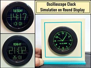 Oscilloscope Clock Simulation on a Round ESP32 Display
An oscilloscope clock is a circuit that turns an old analog oscilloscope into a stylish, retro-them...
Oscilloscope Clock Simulation on a Round ESP32 Display
An oscilloscope clock is a circuit that turns an old analog oscilloscope into a stylish, retro-them...
-
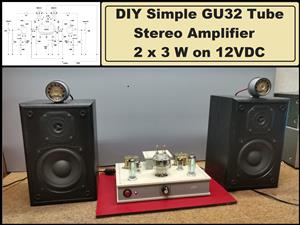 DIY Simple GU32 Tube Stereo Amplifier (2x3W on 12VDC)
Vacuum tube amplifiers are often favored for their smooth harmonic distortion, especially in the low...
DIY Simple GU32 Tube Stereo Amplifier (2x3W on 12VDC)
Vacuum tube amplifiers are often favored for their smooth harmonic distortion, especially in the low...
-
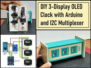 DIY 3-Display OLED Clock with Arduino and I2C Multiplexer
In this video I want to present you another unusual clock to add to my large collection of such DIY...
DIY 3-Display OLED Clock with Arduino and I2C Multiplexer
In this video I want to present you another unusual clock to add to my large collection of such DIY...
-
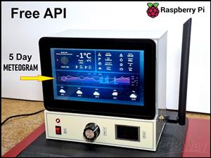 Build a 5-Day forecast Raspberry Pi Weather Dashboard (Step-by-Step)
Recently in one of my previous videos,I introduced you to the 7 inch Elecrow Pi Terminal and how to...
Build a 5-Day forecast Raspberry Pi Weather Dashboard (Step-by-Step)
Recently in one of my previous videos,I introduced you to the 7 inch Elecrow Pi Terminal and how to...
-
 ESP32 Aneroid Barometer using Squareline Studio and LVGL on CrowPanel Round display
A barometer is a scientific instrument used to measure atmospheric pressure. Rising Pressure genera...
ESP32 Aneroid Barometer using Squareline Studio and LVGL on CrowPanel Round display
A barometer is a scientific instrument used to measure atmospheric pressure. Rising Pressure genera...
-
 LINAMP Project – Winamp-Style Audio Front Panel on Raspberry Pi 5
Winamp is one of the most iconic and historically significant digital media players ever created. I...
LINAMP Project – Winamp-Style Audio Front Panel on Raspberry Pi 5
Winamp is one of the most iconic and historically significant digital media players ever created. I...
-
 Retro Style radio with CrowPanel 2.1inch round Display (TEA5767)
Some time ago I presented you a clock project with CrowPanel 2.1inch-HMI ESP32 Rotary Display 480*4...
Retro Style radio with CrowPanel 2.1inch round Display (TEA5767)
Some time ago I presented you a clock project with CrowPanel 2.1inch-HMI ESP32 Rotary Display 480*4...
-
 Pi-Pico RX - SDR Radio with New Firmware and Features
A few months ago I presented you a wonderful SDR radio project by DawsonJon 101 Things. In short, i...
Pi-Pico RX - SDR Radio with New Firmware and Features
A few months ago I presented you a wonderful SDR radio project by DawsonJon 101 Things. In short, i...
-
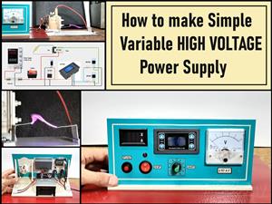 How to make simple Variable HIGH VOLTAGE Power Supply
High Voltage Power Supply is usually understood as a device that is capable of generating a voltage...
How to make simple Variable HIGH VOLTAGE Power Supply
High Voltage Power Supply is usually understood as a device that is capable of generating a voltage...
-
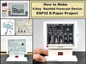 DIY 5-Day Rainfall Forecast Device - ESP32 E-Paper Project
In several of my previous projects I have presented ways to make weather stations, but this time I ...
DIY 5-Day Rainfall Forecast Device - ESP32 E-Paper Project
In several of my previous projects I have presented ways to make weather stations, but this time I ...
-
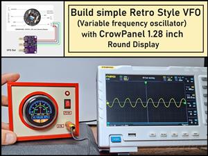 Build simple Retro Style VFO (Variable frequency oscillator) with Crowoanel 1.28 inch Round Display
Today I received a shipment with a Small round LCD display from Elecrow. The device is packed in tw...
Build simple Retro Style VFO (Variable frequency oscillator) with Crowoanel 1.28 inch Round Display
Today I received a shipment with a Small round LCD display from Elecrow. The device is packed in tw...
-
 Human vs Robot – Rock Paper Scissors with MyCobot 280 M5Stack
Today I received a package containing the few Elephant Robotics products. The shipment is well pack...
Human vs Robot – Rock Paper Scissors with MyCobot 280 M5Stack
Today I received a package containing the few Elephant Robotics products. The shipment is well pack...
-
-
ARPS-2 – Arduino-Compatible Robot Project Shield for Arduino UNO
1271 0 4 -
A Compact Charging Breakout Board For Waveshare ESP32-C3
1788 3 7 -
AI-driven LoRa & LLM-enabled Kiosk & Food Delivery System
1773 2 0 -
-
-
-
ESP32-C3 BLE Keyboard - Battery Powered with USB-C Charging
1947 0 1 -


