


|
Soldering Iron Kit |
|

|
arduino IDEArduino
|
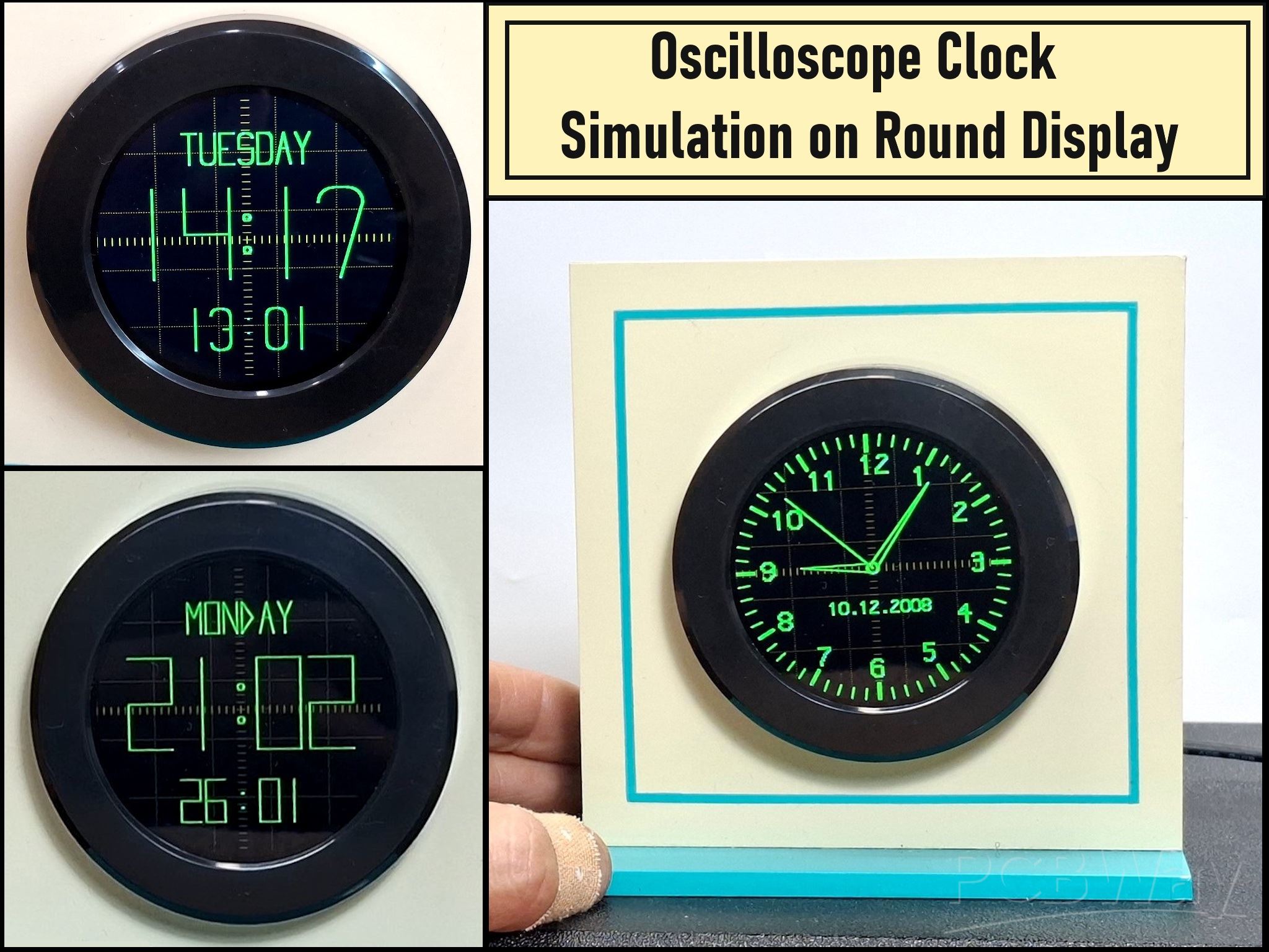
Oscilloscope Clock Simulation on a Round ESP32 Display
An oscilloscope clock is a circuit that turns an old analog oscilloscope into a stylish, retro-themed clock. Cathode Ray Tube (CRT) displays a clock face—either digital or analog—using the screen's ability to draw lines based on voltage. The "X" (horizontal) and "Y" (vertical) inputs of the oscilloscope are controlled by the circuit, and by rapidly changing these voltages, the circuit "draws" numbers or clock hands on the screen. In one of my previous videos , I presented the simplest way to make such a clock yourself.
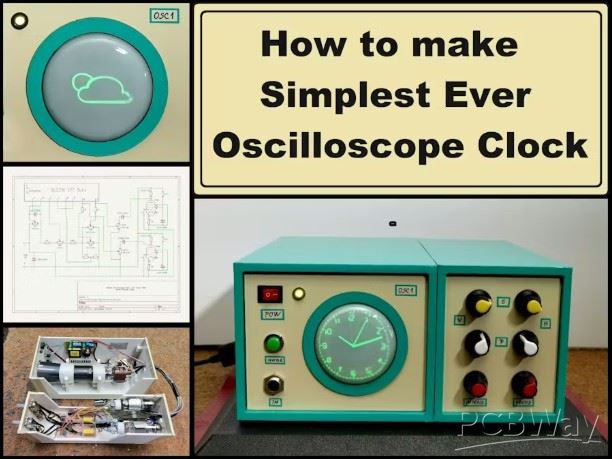
However, its construction requires relatively solid knowledge in the field of electronics and high voltage, and it's also quite expensive.
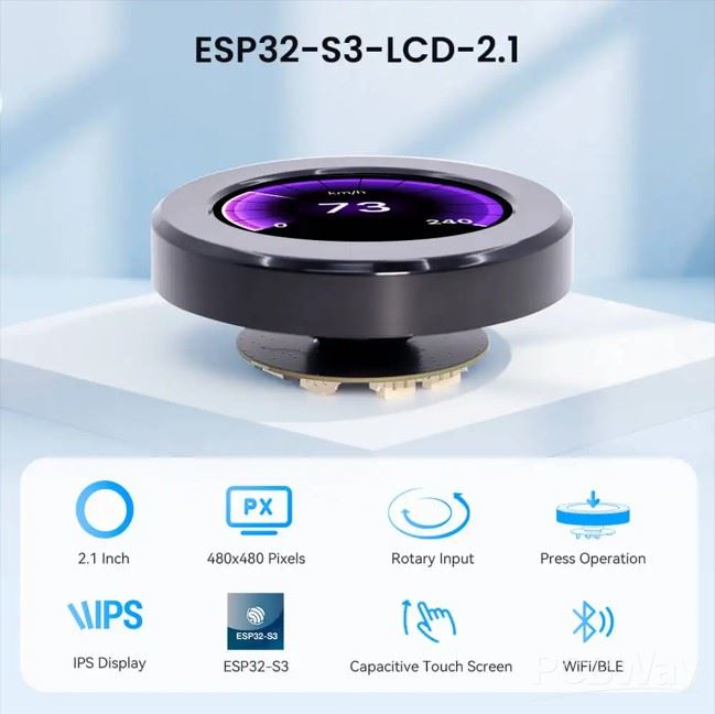
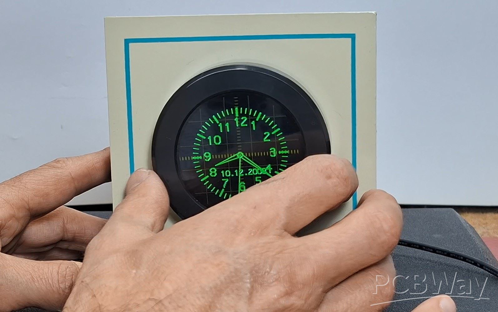
This time I will show you an extremely simple way to make an "oscilloscope clock" on a 2.1 Inch Crowpanel circular display that completely visually imitates the original. Starting from the circular shape of the Display, through the original green color, the marked scale, up to the shape, the way the lines are displayed and illuminated, irresistibly reminds of a CRT Tube.
It is also desirable to mount it in a suitable housing that would resemble a retro CRT oscilloscope for the effect to be maximum.
This project is sponsored by PCBWay . From concept to production, PCBWay provide cutting-edge electronic design solutions for global innovators, Including hardware design, software development, mechanical design, product testing and certification. PCBWay engineering team consists of experienced engineers in electronics, embedded systems, and product development. They successfully delivered hundreds of projects across industries such as medical devices, industrial automation, consumer electronics, smart home, and IoT.

So, to make this clock, no soldering or external components are required. The round display contains a built-in ESP32S3 microcontroller with Wi-Fi and Bluetooth capabilities. We only need to upload the given code, and the device is ready in a few minutes. But before that, certain settings should be noted.
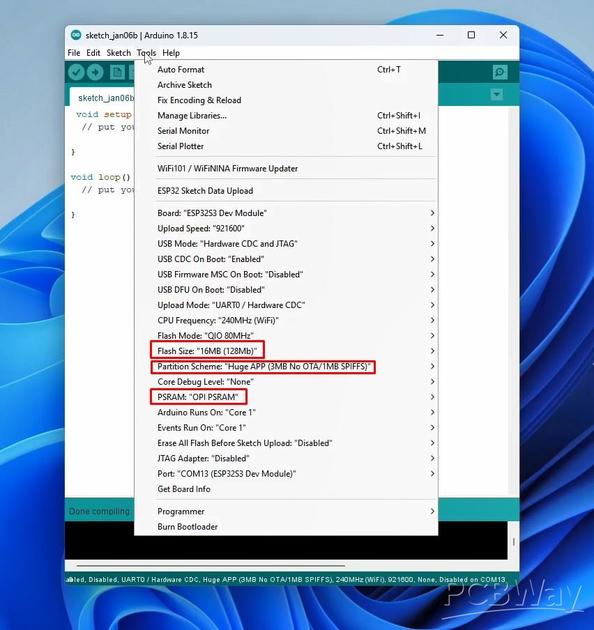
First, you need to use Arduino IDE version 1.8.15 or later. Then you need to install Newest ESP32 Core. Now in Tools-Board-ESP32 Arduino, we need to select ESP32S3 Dev Module. In this board, we need to make several changes to the properties: Flash Size 16MB, Partition scheme- Huge App, and PSRAM - OPI PSRAM.
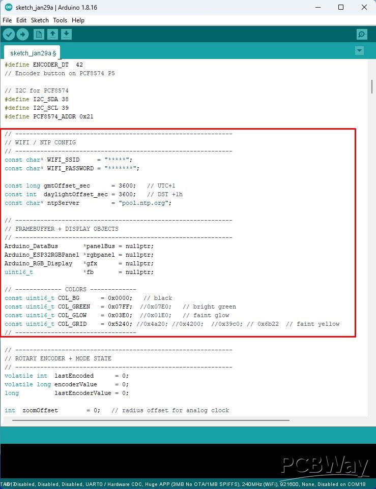
You also need to install the Arduino_GFX_Library. Now we can compile and upload the code without errors. As for the code, the basic settings are located at the beginning, here you need to insert the Wi-Fi credentials, the NTP Server, as well as the definition of the display colors.
Now let's see how the device works in real conditions. Immediately after turning on the clock connects to the Wi-Fi network and gets the correct time from the NTP server. Then an analog clock appears on the display in the style of an Oscilloscope clock with a characteristic green color. Even a "glow" effect has been added when drawing the characters, but unfortunately it is almost not noticeable in the video recording. To make it even closer to the original, I added an option to change the dimensions of the clock using the rotary encoder that is part of the display module.
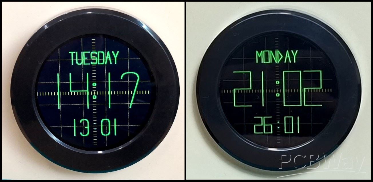
In this way is simulated a change in the amplitude of the signals fed to the X and Y inputs on the original oscilloscope. By pressing the display (the button on the rotary encoder), a digital oscilloscope clock is activated, drawn with arcs and straight lines, which is characteristic of the original oscilloscope version. Here, as before, I introduced a "glow" effect. By pressing again, we return to the analog clock. As for the digital clock, in the first version of the code, the content was formed only by drawing straight lines, which is also characteristic of these devices. At the end of the text, both versions of the code are given.
And finally a short conclusion. By combining the vintage aesthetics of a CRT oscilloscope with modern ESP32 hardware, this project proves you don't need dangerous high voltage to enjoy the classic look of a vector clock. It’s the perfect weekend project for any maker looking to add some retro flair to their desk.
/*==============================================================
   TWO-MODE NTP CLOCK – CrowPanel 2.1" ESP32-S3
   + OSCILLOSCOPE GRID OVERLAY (5x5 with faint yellow dots)

   MODE 0: Analog oscilloscope clock (zoom with encoder)
   MODE 1: Digital clock (Day / HH:MM / Date) with thin CRT lines

   - Rotary encoder CLK/DT: zoom in MODE 0
   - Encoder button on PCF8574 P5: toggle MODE 0 / MODE 1
   - Time from NTP

     by mircemk , Feb 2026
==============================================================*/

#include <Arduino.h>
#include <Arduino_GFX_Library.h>
#include <WiFi.h>
#include <time.h>
#include <Wire.h>

// -------------------------------------------------------------
// DISPLAY CONSTANTS
// -------------------------------------------------------------
#define DISPLAY_WIDTH  480
#define DISPLAY_HEIGHT 480
#define CX 240
#define CY 240

// -------- PANEL PINS (CrowPanel 2.1") --------
#define TYPE_SEL   7
#define PCLK_NEG   1
#define BL_PIN     6
#define PANEL_CS   16
#define PANEL_SCK  2
#define PANEL_SDA  1

// Rotary Encoder pins
#define ENCODER_CLK 4
#define ENCODER_DT  42
// Encoder button on PCF8574 P5

// I2C for PCF8574
#define I2C_SDA 38
#define I2C_SCL 39
#define PCF8574_ADDR 0x21

// -------------------------------------------------------------
// WIFI / NTP CONFIG
// -------------------------------------------------------------
const char* WIFI_SSID     = "*****";
const char* WIFI_PASSWORD = "*******";

const long gmtOffset_sec      = 3600;   // UTC+1
const int  daylightOffset_sec = 3600;   // DST +1h
const char* ntpServer         = "pool.ntp.org";

// -------------------------------------------------------------
// FRAMEBUFFER + DISPLAY OBJECTS
// -------------------------------------------------------------
Arduino_DataBus       *panelBus = nullptr;
Arduino_ESP32RGBPanel *rgbpanel = nullptr;
Arduino_RGB_Display   *gfx      = nullptr;
uint16_t              *fb       = nullptr;

// ------------- COLORS -------------
const uint16_t COL_BG      = 0x0000;   // black
const uint16_t COL_GREEN   = 0x07FF;  //0x07E0;   // bright green
const uint16_t COL_GLOW    = 0x03E0;  //0x01E0;   // faint glow
const uint16_t COL_GRID    = 0x5240; //0x4a20; //0x4200;  //0x39c0; // 0x6b22  // faint yellow
// ----------------------------------

// -------------------------------------------------------------
// ROTARY ENCODER + MODE STATE
// -------------------------------------------------------------
volatile int  lastEncoded      = 0;
volatile long encoderValue     = 0;
long          lastEncoderValue = 0;

int  zoomOffset        = 0;   // radius offset for analog clock
int  clockMode         = 0;   // 0 = analog, 1 = digital

bool lastButtonPressed = false;
unsigned long lastBtnChangeMs  = 0;

// -------------------------------------------------------------
// TIME STATE
// -------------------------------------------------------------
time_t lastSecond = 0;

// -------------------------------------------------------------
// PIXEL HELPERS + GLOW
// -------------------------------------------------------------
static inline void putpix(int x, int y, uint16_t c) {
  if ((unsigned)x < DISPLAY_WIDTH && (unsigned)y < DISPLAY_HEIGHT)
    fb[y * DISPLAY_WIDTH + x] = c;
}

void glow_putpix(int x, int y)
{
  putpix(x, y, COL_GREEN);      // main pixel

  putpix(x+1, y,   COL_GLOW);
  putpix(x-1, y,   COL_GLOW);
  putpix(x,   y+1, COL_GLOW);
  putpix(x,   y-1, COL_GLOW);

  putpix(x+1, y+1, COL_GLOW);
  putpix(x-1, y+1, COL_GLOW);
  putpix(x+1, y-1, COL_GLOW);
  putpix(x-1, y-1, COL_GLOW);
}

void draw_line(int x0,int y0,int x1,int y1,uint16_t col){
  int dx=abs(x1-x0), sx=x0<x1?1:-1;
  int dy=-abs(y1-y0), sy=y0<y1?1:-1;
  int err=dx+dy, e2;

  for(;;){
    glow_putpix(x0, y0);
    if(x0==x1 && y0==y1) break;
    e2 = 2 * err;
    if(e2 >= dy){ err += dy; x0 += sx; }
    if(e2 <= dx){ err += dx; y0 += sy; }
  }
}

void clearFB()
{
  memset(fb, 0, DISPLAY_WIDTH * DISPLAY_HEIGHT * 2);
}

// -------------------------------------------------------------
// OSCILLOSCOPE GRID DRAWING
// -------------------------------------------------------------
void draw_oscilloscope_grid()
{
  // 5x5 major divisions (96 pixels each)
  const int divisions = 5;
  const int spacing = DISPLAY_WIDTH / divisions; // 96 pixels

  // Draw grid with dots instead of lines
  for (int i = 0; i <= divisions; i++) {
    int pos = i * spacing;

    // Vertical grid lines (as dots)
    for (int y = 0; y < DISPLAY_HEIGHT; y += 4) {
      putpix(pos, y, COL_GRID);
    }

    // Horizontal grid lines (as dots)
    for (int x = 0; x < DISPLAY_WIDTH; x += 4) {
      putpix(x, pos, COL_GRID);
    }
  }

  // Add tick marks on center axes (X and Y)
  const int tickSize = 6;
  const int tickSpacing = 12; // Small divisions

  // X-axis tick marks (vertical center line)
  for (int x = 0; x < DISPLAY_WIDTH; x += tickSpacing) {
    for (int ty = -tickSize; ty <= tickSize; ty++) {
      putpix(x, CY + ty, COL_GRID);
    }
  }

  // Y-axis tick marks (horizontal center line)
  for (int y = 0; y < DISPLAY_HEIGHT; y += tickSpacing) {
    for (int tx = -tickSize; tx <= tickSize; tx++) {
      putpix(CX + tx, y, COL_GRID);
    }
  }
}

// -------------------------------------------------------------
// RETRO DIGIT BITMAP FONT (од твојот 0.6A MODE 0)
// -------------------------------------------------------------
const uint8_t RETRO_DIGIT[10][12] PROGMEM = {
  {0b00111100,0b01000010,0b10000001,0b10000001,0b10000001,0b10000001,0b10000001,0b10000001,0b10000001,0b01000010,0b00111100,0},
  {0b00010000,0b00110000,0b01010000,0b00010000,0b00010000,0b00010000,0b00010000,0b00010000,0b00010000,0b00010000,0b00010000,0},
  {0b00111100,0b01000010,0b00000010,0b00000100,0b00001000,0b00010000,0b00100000,0b01000000,0b10000000,0b10000000,0b11111110,0},
  {0b00111100,0b01000010,0b00000010,0b00000010,0b00111100,0b00000010,0b00000010,0b00000010,0b00000010,0b01000010,0b00111100,0},
  {0b00001000,0b00011000,0b00101000,0b01001000,0b10001000,0b11111110,0b00001000,0b00001000,0b00001000,0b00001000,0b00001000,0},
  {0b01111110,0b01000000,0b01000000,0b01000000,0b01111100,0b00000010,0b00000010,0b00000010,0b00000010,0b01000100,0b00111000,0},
  {0b00111100,0b01000010,0b10000000,0b10000000,0b11111100,0b10000010,0b10000010,0b10000010,0b10000010,0b01000010,0b00111100,0},
  {0b11111110,0b00000010,0b00000100,0b00001000,0b00010000,0b00010000,0b00100000,0b00100000,0b01000000,0b01000000,0b01000000,0},
  {0b00111100,0b01000010,0b10000001,0b10000001,0b01000010,0b00111100,0b01000010,0b10000001,0b10000001,0b01000010,0b00111100,0},
  {0b00111100,0b01000010,0b10000001,0b10000001,0b01000011,0b00111101,0b00000001,0b00000001,0b00000010,0b01000100,0b00111000,0}
};

const int GLYPH_W = 8;
const int GLYPH_H = 12;

// ---- Digit drawing with glow (your original) ----
void drawDigitsString(const char *text, int x, int y, int scale)
{
  int len = strlen(text);

  for(int d=0; d<len; d++){
    char c = text[d];

    if(c >= '0' && c <= '9'){
      int digit = c - '0';
      const uint8_t *glyph = RETRO_DIGIT[digit];
      int x0 = x + d*(GLYPH_W*scale + scale);

      for(int row=0; row<GLYPH_H; row++){
        uint8_t bits = pgm_read_byte(&glyph[row]);
        for(int col=0; col<GLYPH_W; col++){
          if(bits & (0x80 >> col)){
            for(int sx=0; sx<scale; sx++)
              for(int sy=0; sy<scale; sy++){
                glow_putpix(x0 + col*scale + sx, y + row*scale + sy);
              }
          }
        }
      }
    }

    if(c=='.'){
      int dotSize = 2*scale;
      int bx = x + d*(GLYPH_W*scale+scale) + GLYPH_W*scale/2 - dotSize/2;
      int by = y + GLYPH_H*scale - dotSize - scale;

      for(int yy=0; yy<dotSize; yy++)
        for(int xx=0; xx<dotSize; xx++)
          glow_putpix(bx+xx, by+yy);
    }
  }
}

// -------------------------------------------------------------
// MODE 0 – ANALOG OSCILLOSCOPE CLOCK (од V0.6A, логика)
// -------------------------------------------------------------
void drawDialNumber(int num, float angleDeg, int radius, int scale)
{
  char buf[4];
  sprintf(buf,"%d",num);

  float a = angleDeg * PI / 180.0f;
  int x = CX + (int)(radius * sin(a));
  int y = CY - (int)(radius * cos(a));

  int w = GLYPH_W * scale;
  drawDigitsString(buf, x - w/2, y - (GLYPH_H*scale)/2, scale);
}

void draw_ring(int cx,int cy,int rOuter,int thickness,uint16_t col)
{
  int rInner = rOuter - thickness;
  int ro2 = rOuter*rOuter;
  int ri2 = rInner*rInner;

  for(int y=-rOuter; y<=rOuter; y++){
    for(int x=-rOuter; x<=rOuter; x++){
      int rr = x*x + y*y;
      if(rr<=ro2 && rr>=ri2){
        glow_putpix(cx+x, cy+y);
      }
    }
  }
}

void draw_clock_face_osc(int zoom)
{
  clearFB();

  // DRAW GRID FIRST (as background layer)
  draw_oscilloscope_grid();

  int R_OUT = 225 + zoom;
  if(R_OUT < 180) R_OUT = 180;
  if(R_OUT > 240) R_OUT = 240;

  const int SHORT_LEN = 20;
  const int LONG_LEN  = 32;

  for(int i=0;i<60;i++){
    float a = i*6.0f * PI/180.0f;

    bool isHour = (i % 5 == 0);
    int len = isHour ? LONG_LEN : SHORT_LEN;
    int thickness = isHour ? 4 : 2;
    int half = thickness/2;

    int x1 = CX + (int)((R_OUT - len)*sin(a));
    int y1 = CY - (int)((R_OUT - len)*cos(a));
    int x2 = CX + (int)(R_OUT*sin(a));
    int y2 = CY - (int)(R_OUT*cos(a));

    float dx = x2 - x1;
    float dy = y2 - y1;

    float px = -dy;
    float py = dx;

    float inv = 1.0f / sqrt(px*px + py*py);
    px *= inv;
    py *= inv;

    for(int k=-half; k<=half; k++){
      int ox = (int)(px*k);
      int oy = (int)(py*k);
      draw_line(x1+ox, y1+oy, x2+ox, y2+oy, COL_GREEN);
    }
  }

  int numRadius = R_OUT - 57;
  for(int n=1;n<=12;n++)
    drawDialNumber(n, n*30.0f, numRadius, 3);

  // пример дата
  drawDigitsString("10.12.2008", CX-80, CY+60, 2);

  draw_ring(CX, CY, 10, 2, COL_GREEN);
}

void draw_clock_hands_osc(int hour,int minute,int second,int zoom)
{
  float secA  = second * 6.0f * PI/180.0f;
  float minA  = (minute + second/60.0f)*6.0f * PI/180.0f;
  float hourA = (hour%12 + minute/60.0f)*30.0f * PI/180.0f;

  const int HUB_R = 10;
  int R_H = 120 + (zoom/3);
  int R_M = 175 + (zoom/3);
  int R_S = 190 + (zoom/3);

  const int W_H = 8;
  const int W_M = 6;

  {   // Hour hand
    float s = sin(hourA), c = cos(hourA);

    int tipX = CX + (int)(R_H*s);
    int tipY = CY - (int)(R_H*c);

    int leftX  = CX + (int)( HUB_R*s + W_H*c );
    int leftY  = CY - (int)( HUB_R*c - W_H*s );

    int rightX = CX + (int)( HUB_R*s - W_H*c );
    int rightY = CY - (int)( HUB_R*c + W_H*s );

    draw_line(leftX, leftY, tipX, tipY, COL_GREEN);
    draw_line(rightX, rightY, tipX, tipY, COL_GREEN);
  }

  {   // Minute hand
    float s = sin(minA), c = cos(minA);

    int tipX = CX + (int)(R_M*s);
    int tipY = CY - (int)(R_M*c);

    int leftX  = CX + (int)( HUB_R*s + W_M*c );
    int leftY  = CY - (int)( HUB_R*c - W_M*s );

    int rightX = CX + (int)( HUB_R*s - W_M*c );
    int rightY = CY - (int)( HUB_R*c + W_M*s );

    draw_line(leftX, leftY, tipX, tipY, COL_GREEN);
    draw_line(rightX, rightY, tipX, tipY, COL_GREEN);
  }

  {   // Second hand
    float s = sin(secA), c = cos(secA);
    int tipX = CX + (int)(R_S*s);
    int tipY = CY - (int)(R_S*c);
    draw_line(CX, CY, tipX, tipY, COL_GREEN);
  }

  draw_ring(CX, CY, HUB_R, 2, COL_GREEN);
}

void draw_mode0_osc_clock(const tm &t)
{
  draw_clock_face_osc(zoomOffset);
  draw_clock_hands_osc(t.tm_hour, t.tm_min, t.tm_sec, zoomOffset);
  gfx->draw16bitRGBBitmap(0,0,fb,DISPLAY_WIDTH,DISPLAY_HEIGHT);
}


// -------------------------------------------------------------
// 5x7 LETTER FONT (A–Z) FOR DAY/DATE
// -------------------------------------------------------------
const uint8_t FONT5x7[26][7] PROGMEM = {
  {0b01110,0b10001,0b10001,0b11111,0b10001,0b10001,0b10001}, // A
  {0b11110,0b10001,0b10001,0b11110,0b10001,0b10001,0b11110}, // B
  {0b01110,0b10001,0b10000,0b10000,0b10000,0b10001,0b01110}, // C
  {0b11100,0b10010,0b10001,0b10001,0b10001,0b10010,0b11100}, // D
  {0b11111,0b10000,0b10000,0b11110,0b10000,0b10000,0b11111}, // E
  {0b11111,0b10000,0b10000,0b11110,0b10000,0b10000,0b10000}, // F
  {0b01110,0b10001,0b10000,0b10111,0b10001,0b10001,0b01110}, // G
  {0b10001,0b10001,0b10001,0b11111,0b10001,0b10001,0b10001}, // H
  {0b01110,0b00100,0b00100,0b00100,0b00100,0b00100,0b01110}, // I
  {0b00111,0b00010,0b00010,0b00010,0b10010,0b10010,0b01100}, // J
  {0b10001,0b10010,0b10100,0b11000,0b10100,0b10010,0b10001}, // K
  {0b10000,0b10000,0b10000,0b10000,0b10000,0b10000,0b11111}, // L
  {0b10001,0b11011,0b10101,0b10101,0b10001,0b10001,0b10001}, // M
  {0b10001,0b10001,0b11001,0b10101,0b10011,0b10001,0b10001}, // N
  {0b01110,0b10001,0b10001,0b10001,0b10001,0b10001,0b01110}, // O
  {0b11110,0b10001,0b10001,0b11110,0b10000,0b10000,0b10000}, // P
  {0b01110,0b10001,0b10001,0b10001,0b10101,0b10010,0b01101}, // Q
  {0b11110,0b10001,0b10001,0b11110,0b10100,0b10010,0b10001}, // R
  {0b01111,0b10000,0b10000,0b01110,0b00001,0b00001,0b11110}, // S
  {0b11111,0b00100,0b00100,0b00100,0b00100,0b00100,0b00100}, // T
  {0b10001,0b10001,0b10001,0b10001,0b10001,0b10001,0b01110}, // U
  {0b10001,0b10001,0b10001,0b01010,0b01010,0b00100,0b00100}, // V
  {0b10001,0b10001,0b10101,0b10101,0b10101,0b11011,0b10001}, // W
  {0b10001,0b01010,0b00100,0b00100,0b00100,0b01010,0b10001}, // X
  {0b10001,0b01010,0b00100,0b00100,0b00100,0b00100,0b00100}, // Y
  {0b11111,0b00001,0b00010,0b00100,0b01000,0b10000,0b11111}  // Z
};

int textWidth5x7(const char *s, int scale) {
  int len = strlen(s);
  if (len == 0) return 0;
  int charW = 5 * scale;
  int gap   = scale;
  return len * (charW + gap) - gap;
}

// -------------------------------------------------------------
// MODE 1 – THIN CRT-STYLE DIGITAL CLOCK (Day / HH:MM / Date)
// -------------------------------------------------------------
// -------------------------------------------------------------
// THIN VECTOR CRT DIGITS – improved spacing
// -------------------------------------------------------------

// ============================================================
// FIXED ROUNDED CRT CHARACTERS - Целосно поправена верзија
// ============================================================

// HELPER: Draw arc (четвртина круг) - ПРАВИЛНА ОРИЕНТАЦИЈА
void draw_arc(int cx, int cy, int radius, int startAngle, int endAngle)
{
  // startAngle и endAngle се во степени (0-360)
  for (int angle = startAngle; angle <= endAngle; angle += 2) {
    float rad = angle * PI / 180.0f;
    int x = cx + (int)(radius * cos(rad));
    int y = cy + (int)(radius * sin(rad));
    glow_putpix(x, y);
  }
}

// КРУЖЧИЊА ЗА ДВОТОЧКА
void draw_colon_rounded(int cx, int cy, int height) {
  int dotRadius = (int)(height * 0.04f);
  int offset = (int)(height * 0.18f);

  // Горно кружче
  for(int angle = 0; angle < 360; angle += 8) {
    float rad = angle * PI / 180.0f;
    int x = cx + (int)(dotRadius * cos(rad));
    int y = (cy - offset) + (int)(dotRadius * sin(rad));
    glow_putpix(x, y);
  }

  // Долно кружче
  for(int angle = 0; angle < 360; angle += 8) {
    float rad = angle * PI / 180.0f;
    int x = cx + (int)(dotRadius * cos(rad));
    int y = (cy + offset) + (int)(dotRadius * sin(rad));
    glow_putpix(x, y);
  }
}

// ============================================================
// ROUNDED DIGIT (0-9) - ЦЕЛОСНО РЕКОНСТРУИРАНИ
// ============================================================
void roundedDigit(int d, int cx, int cy, int h)
{
  int w = h * 0.48;
  int r = w / 3;

  int top = cy - h/2;
  int bot = cy + h/2;
  int mid = cy;

  int left = cx - w/2;
  int right = cx + w/2;

  switch(d)
  {
    case 0: // Заоблен правоаголник
      // Горни лации
      draw_arc(left + r, top + r, r, 180, 270);   // top-left
      draw_arc(right - r, top + r, r, 270, 360);  // top-right
      // Долни лации
      draw_arc(right - r, bot - r, r, 0, 90);     // bottom-right
      draw_arc(left + r, bot - r, r, 90, 180);    // bottom-left
      // Прави линии
      draw_line(left + r, top, right - r, top, COL_GREEN);
      draw_line(right, top + r, right, bot - r, COL_GREEN);
      draw_line(right - r, bot, left + r, bot, COL_GREEN);
      draw_line(left, bot - r, left, top + r, COL_GREEN);
      break;

    case 1: // Вертикална линија
      draw_line(cx, top, cx, bot, COL_GREEN);
      break;

    case 2: // S-форма
      draw_arc(left + r, top + r, r, 180, 270);
      draw_arc(right - r, top + r, r, 270, 360);
      draw_line(left + r, top, right - r, top, COL_GREEN);
      draw_line(right, top + r, right, mid, COL_GREEN);
      draw_line(right, mid, left, mid, COL_GREEN);
      draw_line(left, mid, left, bot - r, COL_GREEN);
      draw_arc(left + r, bot - r, r, 90, 180);
      draw_arc(right - r, bot - r, r, 0, 90);
      draw_line(left + r, bot, right - r, bot, COL_GREEN);
      break;

    case 3: // Десно заоблена
      draw_arc(left + r, top + r, r, 180, 270);
      draw_arc(right - r, top + r, r, 270, 360);
      draw_line(left + r, top, right - r, top, COL_GREEN);
      draw_line(right, top + r, right, mid, COL_GREEN);
      draw_line(right - w/3, mid, right, mid, COL_GREEN);
      draw_line(right, mid, right, bot - r, COL_GREEN);
      draw_arc(right - r, bot - r, r, 0, 90);
      draw_arc(left + r, bot - r, r, 90, 180);
      draw_line(right - r, bot, left + r, bot, COL_GREEN);
      break;

    case 4: // 4
      draw_line(left, top, left, mid, COL_GREEN);
      draw_line(left, mid, right, mid, COL_GREEN);
      draw_line(right, top, right, bot, COL_GREEN);
      break;

    case 5: // S-обратно
      draw_arc(right - r, top + r, r, 270, 360);
      draw_arc(left + r, top + r, r, 180, 270);
      draw_line(right - r, top, left + r, top, COL_GREEN);
      draw_line(left, top + r, left, mid, COL_GREEN);
      draw_line(left, mid, right, mid, COL_GREEN);
      draw_line(right, mid, right, bot - r, COL_GREEN);
      draw_arc(right - r, bot - r, r, 0, 90);
      draw_arc(left + r, bot - r, r, 90, 180);
      draw_line(right - r, bot, left + r, bot, COL_GREEN);
      break;

    case 6: // 6
      draw_arc(right - r, top + r, r, 270, 360);
      draw_line(right - r, top, left + r, top, COL_GREEN);
      draw_arc(left + r, top + r, r, 180, 270);
      draw_line(left, top + r, left, bot - r, COL_GREEN);
      draw_arc(left + r, bot - r, r, 90, 180);
      draw_line(left + r, bot, right - r, bot, COL_GREEN);
      draw_arc(right - r, bot - r, r, 0, 90);
      draw_line(right, bot - r, right, mid, COL_GREEN);
      draw_line(right, mid, left, mid, COL_GREEN);
      break;

    case 7: // 7
      draw_arc(left + r, top + r, r, 180, 270);
      draw_line(left + r, top, right - r, top, COL_GREEN);
      draw_arc(right - r, top + r, r, 270, 360);
      draw_line(right, top + r, cx, bot, COL_GREEN);
      break;

    case 8: // 8 - две петли
      // Горна петла
      draw_arc(left + r, top + r, r, 180, 270);
      draw_line(left + r, top, right - r, top, COL_GREEN);
      draw_arc(right - r, top + r, r, 270, 360);
      draw_line(right, top + r, right, mid, COL_GREEN);
      draw_line(right, mid, left, mid, COL_GREEN);
      draw_line(left, mid, left, top + r, COL_GREEN);
      // Долна петла
      draw_line(left, mid, left, bot - r, COL_GREEN);
      draw_arc(left + r, bot - r, r, 90, 180);
      draw_line(left + r, bot, right - r, bot, COL_GREEN);
      draw_arc(right - r, bot - r, r, 0, 90);
      draw_line(right, bot - r, right, mid, COL_GREEN);
      break;

    case 9: // 9
      draw_arc(left + r, top + r, r, 180, 270);
      draw_line(left + r, top, right - r, top, COL_GREEN);
      draw_arc(right - r, top + r, r, 270, 360);
      draw_line(right, top + r, right, bot - r, COL_GREEN);
      draw_line(right, mid, left, mid, COL_GREEN);
      draw_line(left, mid, left, top + r, COL_GREEN);
      draw_arc(left + r, bot - r, r, 90, 180);
      draw_line(left + r, bot, right - r, bot, COL_GREEN);
      draw_arc(right - r, bot - r, r, 0, 90);
      break;
  }
}


// ============================================================
// ROUNDED LETTER (потребни букви)
// ============================================================
void roundedLetter(char c, int cx, int cy, int h)
{
  int w = h * 0.45;
  int r = w / 3;

  int top = cy - h/2;
  int bot = cy + h/2;
  int mid = cy;

  int left = cx - w/2;
  int right = cx + w/2;

  switch(c)
  {
    case 'O': // Како 0
      draw_arc(left + r, top + r, r, 180, 270);
      draw_arc(right - r, top + r, r, 270, 360);
      draw_line(left + r, top, right - r, top, COL_GREEN);
      draw_line(right, top + r, right, bot - r, COL_GREEN);
      draw_arc(right - r, bot - r, r, 0, 90);
      draw_line(right - r, bot, left + r, bot, COL_GREEN);
      draw_arc(left + r, bot - r, r, 90, 180);
      draw_line(left, bot - r, left, top + r, COL_GREEN);
      break;

    case 'A':
      draw_line(left, bot, cx, top, COL_GREEN);
      draw_line(cx, top, right, bot, COL_GREEN);
      draw_line(left + w/4, mid, right - w/4, mid, COL_GREEN);
      break;

    case 'D':
      draw_line(left, top, left, bot, COL_GREEN);
      draw_line(left, top, cx + r, top, COL_GREEN);
      draw_arc(right - r, top + r, r, 270, 360);
      draw_line(right, top + r, right, bot - r, COL_GREEN);
      draw_arc(right - r, bot - r, r, 0, 90);
      draw_line(cx + r, bot, left, bot, COL_GREEN);
      break;

    case 'F':
      draw_line(left, top, left, bot, COL_GREEN);
      draw_line(left, top, right, top, COL_GREEN);
      draw_line(left, mid, cx, mid, COL_GREEN);
      break;

    case 'I':
      draw_line(cx, top, cx, bot, COL_GREEN);
      break;

    case 'M':
      draw_line(left, bot, left, top, COL_GREEN);
      draw_line(left, top, cx, mid, COL_GREEN);
      draw_line(cx, mid, right, top, COL_GREEN);
      draw_line(right, top, right, bot, COL_GREEN);
      break;

    case 'N':
      draw_line(left, bot, left, top, COL_GREEN);
      draw_line(left, top, right, bot, COL_GREEN);
      draw_line(right, bot, right, top, COL_GREEN);
      break;

    case 'R':
      draw_line(left, bot, left, top, COL_GREEN);
      draw_line(left, top, right - r, top, COL_GREEN);
      draw_arc(right - r, top + r, r, 270, 360);
      draw_line(right, top + r, right, mid - r, COL_GREEN);
      draw_arc(right - r, mid - r, r, 0, 90);
      draw_line(right - r, mid, left, mid, COL_GREEN);
      draw_line(cx, mid, right, bot, COL_GREEN);
      break;

    case 'S': // Како 5
      draw_arc(right - r, top + r, r, 270, 360);
      draw_line(right - r, top, left + r, top, COL_GREEN);
      draw_arc(left + r, top + r, r, 180, 270);
      draw_line(left, top + r, left, mid, COL_GREEN);
      draw_line(left, mid, right, mid, COL_GREEN);
      draw_line(right, mid, right, bot - r, COL_GREEN);
      draw_arc(right - r, bot - r, r, 0, 90);
      draw_line(right - r, bot, left + r, bot, COL_GREEN);
      draw_arc(left + r, bot - r, r, 90, 180);
      break;

    case 'T':
      draw_line(left, top, right, top, COL_GREEN);
      draw_line(cx, top, cx, bot, COL_GREEN);
      break;

    case 'U':
      draw_line(left, top, left, bot - r, COL_GREEN);
      draw_arc(left + r, bot - r, r, 90, 180);
      draw_line(left + r, bot, right - r, bot, COL_GREEN);
      draw_arc(right - r, bot - r, r, 0, 90);
      draw_line(right, bot - r, right, top, COL_GREEN);
      break;

    case 'E':
      draw_line(left, top, left, bot, COL_GREEN);
      draw_line(left, top, right, top, COL_GREEN);
      draw_line(left, mid, cx, mid, COL_GREEN);
      draw_line(left, bot, right, bot, COL_GREEN);
      break;

    case 'Y':
      draw_line(left, top, cx, mid, COL_GREEN);
      draw_line(right, top, cx, mid, COL_GREEN);
      draw_line(cx, mid, cx, bot, COL_GREEN);
      break;

    case 'W':
      draw_line(left, top, left, bot, COL_GREEN);
      draw_line(left, bot, cx, mid, COL_GREEN);
      draw_line(cx, mid, right, bot, COL_GREEN);
      draw_line(right, bot, right, top, COL_GREEN);
      break;

    case 'H':
      draw_line(left, top, left, bot, COL_GREEN);
      draw_line(left, mid, right, mid, COL_GREEN);
      draw_line(right, top, right, bot, COL_GREEN);
      break;
  }
}
// -------------------------------------------------------------
// DRAW DAY OF THE WEEK (Vector Thin) - CENTERED
// -------------------------------------------------------------
void drawWeekday_VectorThin(const char* name, int centerY, int height) {
  int len = strlen(name);
  int step = height * 0.6;

  // 1. Calculate the character width 'w' (as defined in thinLetter: w = h * 0.45)
  int w = (int)(height * 0.45);

  // 2. Calculate the total visual width of the word.
  // Total Width = (len - 1 gaps * step) + (1 character width)
  int total_width = (len - 1) * step + w;

  // 3. Calculate the X coordinate of the center of the first letter (startX).
  // The goal is to set the center of the *entire word* at CX (240).
  // startX = (Center of screen CX) - (Half of total width) + (Half of first character width)
  // This correctly positions the center of the first letter.
  int startX = CX - total_width / 2 + w / 2;

  for (int i = 0; i < len; i++) {
   roundedLetter(name[i], startX + i * step, centerY, height);
  }
}

// -------------------------------------------------------------
// Draw HH:MM with improved spacing and adjusted position
// -------------------------------------------------------------
void drawTimeHHMM_VectorThin(int hour, int minute, int centerY, int height)
{
  int w = height * 0.48;
  int spacing = height * 0.1;
  const int OFFSET_X = 20;

  int cxH1 = CX - (w * 1.5 + spacing * 1.5) - OFFSET_X;
  int cxH2 = CX - (w * 0.5 + spacing * 0.5) - OFFSET_X;
  int cxM1 = CX + (w * 0.5 + spacing * 0.5) + OFFSET_X;
  int cxM2 = CX + (w * 1.5 + spacing * 1.5) + OFFSET_X;

  roundedDigit(hour/10, cxH1, centerY, height);
  roundedDigit(hour%10, cxH2, centerY, height);

  // КРУЖЧИЊА НАМЕСТО ТОЧКИ
  draw_colon_rounded(CX, centerY, height);

  roundedDigit(minute/10, cxM1, centerY, height);
  roundedDigit(minute%10, cxM2, centerY, height);
}
void drawDateDDMM_VectorThin(int day, int month, int centerY, int height)
{
  // digit "visual width" used by thinDigit()
  int w = (int)(height * 0.48f);
  int digitStep = w + (int)(height * 0.12f);

  // bigger separation between DD and MM (you asked "a little further apart")
  int colonGap = (int)(height * 0.65f);

  // positions (FORCED symmetry around CX)
  int cxD1 = CX - (digitStep + colonGap);
  int cxD2 = CX - (colonGap);
  int cxM1 = CX + (colonGap);
  int cxM2 = CX + (digitStep + colonGap);

  // draw digits
   roundedDigit((day / 10) % 10, cxD1, centerY, height);
   roundedDigit(day % 10, cxD2, centerY, height);

  // dots: SAME X as time (CX), and a bit higher as you requested
  int colonCenterY = centerY - (int)(height * 0.08f);
  int dotOff = (int)(height * 0.18f);
  glow_putpix(CX, colonCenterY - dotOff);
  glow_putpix(CX, colonCenterY + dotOff);

   roundedDigit((month / 10) % 10, cxM1, centerY, height);
   roundedDigit(month % 10, cxM2, centerY, height);
}

void draw_mode1_digital_clock(const tm &t)
{
  clearFB();

  // DRAW GRID FIRST (as background layer)
  draw_oscilloscope_grid();

  // ----- Day name (top) -----
  static const char* days[] =
  {
    "SUNDAY", "MONDAY", "TUESDAY",
    "WEDNESDAY", "THURSDAY", "FRIDAY", "SATURDAY"
  };

  int dayY = CY - 150;     // same vertical region you already use
  int dayH = 50;           // thin size

  drawWeekday_VectorThin(days[t.tm_wday], dayY, dayH);

  // ----- Time HH:MM (center) -----
  drawTimeHHMM_VectorThin(t.tm_hour, t.tm_min, CY - 10, 150);

  // ----- Date (thin CRT, numeric) -----
  drawDateDDMM_VectorThin(
    t.tm_mday,
    t.tm_mon + 1,
    (CY - 10) + 160,   // +10 / -10 можеш тука да си играш
    70                // height на цифри (препорачано 60–80)
  );

  gfx->draw16bitRGBBitmap(0, 0, fb, DISPLAY_WIDTH, DISPLAY_HEIGHT);
}

// -------------------------------------------------------------
// DRAW FRAME: PICK MODE
// -------------------------------------------------------------
void drawClockFrame() {
  struct tm timeinfo;
  if (!getLocalTime(&timeinfo)) {
    return;
  }

  if (clockMode == 0)
    draw_mode0_osc_clock(timeinfo);
  else
    draw_mode1_digital_clock(timeinfo);
}

// -------------------------------------------------------------
// DISPLAY INIT – SAME STYLE AS YOUR WORKING PANEL
// -------------------------------------------------------------
extern const uint8_t st7701_type7_init_operations[];

void init_display() {
  pinMode(BL_PIN, OUTPUT);
  digitalWrite(BL_PIN, HIGH);

  // исто како во твојот 0.6A
  panelBus = new Arduino_SWSPI(
    GFX_NOT_DEFINED, PANEL_CS, PANEL_SCK, PANEL_SDA, GFX_NOT_DEFINED
  );

  rgbpanel = new Arduino_ESP32RGBPanel(
      40,7,15,41,
      46,3,8,18,17,
      14,13,12,11,10,9,
      5,45,48,47,21,
      1,50,10,50,
      1,30,10,30,
      PCLK_NEG,8000000UL
  );

  // КЛУЧОТ: користи го ST7701 TYPE7 init од библиотеката
  gfx = new Arduino_RGB_Display(
    DISPLAY_WIDTH, DISPLAY_HEIGHT, rgbpanel, 0, true,
    panelBus, GFX_NOT_DEFINED,
    st7701_type7_init_operations, sizeof(st7701_type7_init_operations)
  );

  gfx->begin(16000000);

  fb = (uint16_t*)ps_malloc(DISPLAY_WIDTH * DISPLAY_HEIGHT * 2);
}

// -------------------------------------------------------------
// PCF8574: INIT + READ + BUTTON
// -------------------------------------------------------------
void pcf8574_init() {
  Wire.begin(I2C_SDA, I2C_SCL);
  Wire.beginTransmission(PCF8574_ADDR);
  Wire.write(0xFF);        // all high → inputs with weak pull-ups
  Wire.endTransmission();
}

uint8_t pcf8574_read() {
  Wire.requestFrom(PCF8574_ADDR, (uint8_t)1);
  if (Wire.available())
    return Wire.read();
  return 0xFF;
}

bool isEncoderButtonPressed() {
  uint8_t state = pcf8574_read();
  return !(state & (1 << 5));   // P5 low = pressed
}

// -------------------------------------------------------------
// ROTARY ENCODER ISR + HANDLER
// -------------------------------------------------------------
void IRAM_ATTR updateEncoder() {
  int MSB = digitalRead(ENCODER_CLK);
  int LSB = digitalRead(ENCODER_DT);

  int encoded = (MSB << 1) | LSB;
  int sum = (lastEncoded << 2) | encoded;

  if (sum == 0b1101 || sum == 0b0100 || sum == 0b0010 || sum == 0b1011)
    encoderValue++;
  if (sum == 0b1110 || sum == 0b0111 || sum == 0b0001 || sum == 0b1000)
    encoderValue--;

  lastEncoded = encoded;
}

bool handleEncoderAndButtons() {
  bool needRedraw = false;

  noInterrupts();
  long currentValue = encoderValue;
  interrupts();

  if (currentValue != lastEncoderValue && clockMode == 0) {
    long diff = currentValue - lastEncoderValue;
    zoomOffset += (int)diff;
    if (zoomOffset < -40) zoomOffset = -40;
    if (zoomOffset >  40) zoomOffset =  40;
    lastEncoderValue = currentValue;
    needRedraw = true;
  }

  bool pressed = isEncoderButtonPressed();
  unsigned long nowMs = millis();

  if (pressed && !lastButtonPressed && (nowMs - lastBtnChangeMs) > 200) {
    clockMode ^= 1;            // toggle 0/1
    lastBtnChangeMs = nowMs;
    needRedraw = true;
  }

  lastButtonPressed = pressed;
  return needRedraw;
}

// -------------------------------------------------------------
// WIFI + NTP INIT
// -------------------------------------------------------------
void connectWiFiAndTime() {
  WiFi.mode(WIFI_STA);
  WiFi.begin(WIFI_SSID, WIFI_PASSWORD);
  Serial.print("Connecting to WiFi");
  while (WiFi.status() != WL_CONNECTED) {
    Serial.print(".");
    delay(500);
  }
  Serial.println("\nWiFi connected");

  configTime(gmtOffset_sec, daylightOffset_sec, ntpServer);

  struct tm timeinfo;
  for (int i = 0; i < 30; i++) {
    if (getLocalTime(&timeinfo)) {
      Serial.println("Time acquired from NTP");
      return;
    }
    delay(500);
  }
  Serial.println("Failed to get time from NTP (will still try in loop).");
}

// -------------------------------------------------------------
// SETUP / LOOP
// -------------------------------------------------------------
void setup() {
  Serial.begin(115200);

  pinMode(ENCODER_CLK, INPUT_PULLUP);
  pinMode(ENCODER_DT,  INPUT_PULLUP);

  attachInterrupt(digitalPinToInterrupt(ENCODER_CLK), updateEncoder, CHANGE);
  attachInterrupt(digitalPinToInterrupt(ENCODER_DT),  updateEncoder, CHANGE);

  init_display();
  pcf8574_init();
  connectWiFiAndTime();

  clearFB();
  drawClockFrame();
}

void loop() {
  bool needRedraw = false;

  if (handleEncoderAndButtons()) {
    needRedraw = true;
  }

  time_t nowSec = time(nullptr);
  if (nowSec != lastSecond && nowSec > 100000) {
    lastSecond = nowSec;
    needRedraw = true;
  }

  if (needRedraw) {
    drawClockFrame();
  }

  delay(10);
}
/*==============================================================
   TWO-MODE NTP CLOCK – CrowPanel 2.1" ESP32-S3
   + OSCILLOSCOPE GRID OVERLAY (5x5 with faint yellow dots)

   MODE 0: Analog oscilloscope clock (zoom with encoder)
   MODE 1: Digital clock (Day / HH:MM / Date) with thin CRT lines

   - Rotary encoder CLK/DT: zoom in MODE 0
   - Encoder button on PCF8574 P5: toggle MODE 0 / MODE 1
   - Time from NTP

    by mircemk , Feb 2026
==============================================================*/

#include <Arduino.h>
#include <Arduino_GFX_Library.h>
#include <WiFi.h>
#include <time.h>
#include <Wire.h>

// -------------------------------------------------------------
// DISPLAY CONSTANTS
// -------------------------------------------------------------
#define DISPLAY_WIDTH  480
#define DISPLAY_HEIGHT 480
#define CX 240
#define CY 240

// -------- PANEL PINS (CrowPanel 2.1") --------
#define TYPE_SEL   7
#define PCLK_NEG   1
#define BL_PIN     6
#define PANEL_CS   16
#define PANEL_SCK  2
#define PANEL_SDA  1

// Rotary Encoder pins
#define ENCODER_CLK 4
#define ENCODER_DT  42
// Encoder button on PCF8574 P5

// I2C for PCF8574
#define I2C_SDA 38
#define I2C_SCL 39
#define PCF8574_ADDR 0x21

// -------------------------------------------------------------
// WIFI / NTP CONFIG
// -------------------------------------------------------------
const char* WIFI_SSID     = "Infobiro";
const char* WIFI_PASSWORD = "CfmaWmsIb1991!";

const long gmtOffset_sec      = 3600;   // UTC+1
const int  daylightOffset_sec = 3600;   // DST +1h
const char* ntpServer         = "pool.ntp.org";

// -------------------------------------------------------------
// FRAMEBUFFER + DISPLAY OBJECTS
// -------------------------------------------------------------
Arduino_DataBus       *panelBus = nullptr;
Arduino_ESP32RGBPanel *rgbpanel = nullptr;
Arduino_RGB_Display   *gfx      = nullptr;
uint16_t              *fb       = nullptr;

// ------------- COLORS -------------
const uint16_t COL_BG      = 0x0000;   // black
const uint16_t COL_GREEN   = 0x07FF;  //0x07E0;   // bright green
const uint16_t COL_GLOW    = 0x03E0;  //0x01E0;   // faint glow
const uint16_t COL_GRID    = 0x5240; //0x4a20; //0x4200;  //0x39c0;  // faint yellow
// ----------------------------------

// -------------------------------------------------------------
// ROTARY ENCODER + MODE STATE
// -------------------------------------------------------------
volatile int  lastEncoded      = 0;
volatile long encoderValue     = 0;
long          lastEncoderValue = 0;

int  zoomOffset        = 0;   // radius offset for analog clock
int  clockMode         = 0;   // 0 = analog, 1 = digital

bool lastButtonPressed = false;
unsigned long lastBtnChangeMs  = 0;

// -------------------------------------------------------------
// TIME STATE
// -------------------------------------------------------------
time_t lastSecond = 0;

// -------------------------------------------------------------
// PIXEL HELPERS + GLOW
// -------------------------------------------------------------
static inline void putpix(int x, int y, uint16_t c) {
  if ((unsigned)x < DISPLAY_WIDTH && (unsigned)y < DISPLAY_HEIGHT)
    fb[y * DISPLAY_WIDTH + x] = c;
}

void glow_putpix(int x, int y)
{
  putpix(x, y, COL_GREEN);      // main pixel

  putpix(x+1, y,   COL_GLOW);
  putpix(x-1, y,   COL_GLOW);
  putpix(x,   y+1, COL_GLOW);
  putpix(x,   y-1, COL_GLOW);

  putpix(x+1, y+1, COL_GLOW);
  putpix(x-1, y+1, COL_GLOW);
  putpix(x+1, y-1, COL_GLOW);
  putpix(x-1, y-1, COL_GLOW);
}

void draw_line(int x0,int y0,int x1,int y1,uint16_t col){
  int dx=abs(x1-x0), sx=x0<x1?1:-1;
  int dy=-abs(y1-y0), sy=y0<y1?1:-1;
  int err=dx+dy, e2;

  for(;;){
    glow_putpix(x0, y0);
    if(x0==x1 && y0==y1) break;
    e2 = 2 * err;
    if(e2 >= dy){ err += dy; x0 += sx; }
    if(e2 <= dx){ err += dx; y0 += sy; }
  }
}

void clearFB()
{
  memset(fb, 0, DISPLAY_WIDTH * DISPLAY_HEIGHT * 2);
}

// -------------------------------------------------------------
// OSCILLOSCOPE GRID DRAWING
// -------------------------------------------------------------
void draw_oscilloscope_grid()
{
  // 5x5 major divisions (96 pixels each)
  const int divisions = 5;
  const int spacing = DISPLAY_WIDTH / divisions; // 96 pixels

  // Draw grid with dots instead of lines
  for (int i = 0; i <= divisions; i++) {
    int pos = i * spacing;

    // Vertical grid lines (as dots)
    for (int y = 0; y < DISPLAY_HEIGHT; y += 4) {
      putpix(pos, y, COL_GRID);
    }

    // Horizontal grid lines (as dots)
    for (int x = 0; x < DISPLAY_WIDTH; x += 4) {
      putpix(x, pos, COL_GRID);
    }
  }

  // Add tick marks on center axes (X and Y)
  const int tickSize = 6;
  const int tickSpacing = 12; // Small divisions

  // X-axis tick marks (vertical center line)
  for (int x = 0; x < DISPLAY_WIDTH; x += tickSpacing) {
    for (int ty = -tickSize; ty <= tickSize; ty++) {
      putpix(x, CY + ty, COL_GRID);
    }
  }

  // Y-axis tick marks (horizontal center line)
  for (int y = 0; y < DISPLAY_HEIGHT; y += tickSpacing) {
    for (int tx = -tickSize; tx <= tickSize; tx++) {
      putpix(CX + tx, y, COL_GRID);
    }
  }
}

// -------------------------------------------------------------
// RETRO DIGIT BITMAP FONT (од твојот 0.6A MODE 0)
// -------------------------------------------------------------
const uint8_t RETRO_DIGIT[10][12] PROGMEM = {
  {0b00111100,0b01000010,0b10000001,0b10000001,0b10000001,0b10000001,0b10000001,0b10000001,0b10000001,0b01000010,0b00111100,0},
  {0b00010000,0b00110000,0b01010000,0b00010000,0b00010000,0b00010000,0b00010000,0b00010000,0b00010000,0b00010000,0b00010000,0},
  {0b00111100,0b01000010,0b00000010,0b00000100,0b00001000,0b00010000,0b00100000,0b01000000,0b10000000,0b10000000,0b11111110,0},
  {0b00111100,0b01000010,0b00000010,0b00000010,0b00111100,0b00000010,0b00000010,0b00000010,0b00000010,0b01000010,0b00111100,0},
  {0b00001000,0b00011000,0b00101000,0b01001000,0b10001000,0b11111110,0b00001000,0b00001000,0b00001000,0b00001000,0b00001000,0},
  {0b01111110,0b01000000,0b01000000,0b01000000,0b01111100,0b00000010,0b00000010,0b00000010,0b00000010,0b01000100,0b00111000,0},
  {0b00111100,0b01000010,0b10000000,0b10000000,0b11111100,0b10000010,0b10000010,0b10000010,0b10000010,0b01000010,0b00111100,0},
  {0b11111110,0b00000010,0b00000100,0b00001000,0b00010000,0b00010000,0b00100000,0b00100000,0b01000000,0b01000000,0b01000000,0},
  {0b00111100,0b01000010,0b10000001,0b10000001,0b01000010,0b00111100,0b01000010,0b10000001,0b10000001,0b01000010,0b00111100,0},
  {0b00111100,0b01000010,0b10000001,0b10000001,0b01000011,0b00111101,0b00000001,0b00000001,0b00000010,0b01000100,0b00111000,0}
};

const int GLYPH_W = 8;
const int GLYPH_H = 12;

// ---- Digit drawing with glow (your original) ----
void drawDigitsString(const char *text, int x, int y, int scale)
{
  int len = strlen(text);

  for(int d=0; d<len; d++){
    char c = text[d];

    if(c >= '0' && c <= '9'){
      int digit = c - '0';
      const uint8_t *glyph = RETRO_DIGIT[digit];
      int x0 = x + d*(GLYPH_W*scale + scale);

      for(int row=0; row<GLYPH_H; row++){
        uint8_t bits = pgm_read_byte(&glyph[row]);
        for(int col=0; col<GLYPH_W; col++){
          if(bits & (0x80 >> col)){
            for(int sx=0; sx<scale; sx++)
              for(int sy=0; sy<scale; sy++){
                glow_putpix(x0 + col*scale + sx, y + row*scale + sy);
              }
          }
        }
      }
    }

    if(c=='.'){
      int dotSize = 2*scale;
      int bx = x + d*(GLYPH_W*scale+scale) + GLYPH_W*scale/2 - dotSize/2;
      int by = y + GLYPH_H*scale - dotSize - scale;

      for(int yy=0; yy<dotSize; yy++)
        for(int xx=0; xx<dotSize; xx++)
          glow_putpix(bx+xx, by+yy);
    }
  }
}

// -------------------------------------------------------------
// MODE 0 – ANALOG OSCILLOSCOPE CLOCK (од V0.6A, логика)
// -------------------------------------------------------------
void drawDialNumber(int num, float angleDeg, int radius, int scale)
{
  char buf[4];
  sprintf(buf,"%d",num);

  float a = angleDeg * PI / 180.0f;
  int x = CX + (int)(radius * sin(a));
  int y = CY - (int)(radius * cos(a));

  int w = GLYPH_W * scale;
  drawDigitsString(buf, x - w/2, y - (GLYPH_H*scale)/2, scale);
}

void draw_ring(int cx,int cy,int rOuter,int thickness,uint16_t col)
{
  int rInner = rOuter - thickness;
  int ro2 = rOuter*rOuter;
  int ri2 = rInner*rInner;

  for(int y=-rOuter; y<=rOuter; y++){
    for(int x=-rOuter; x<=rOuter; x++){
      int rr = x*x + y*y;
      if(rr<=ro2 && rr>=ri2){
        glow_putpix(cx+x, cy+y);
      }
    }
  }
}

void draw_clock_face_osc(int zoom)
{
  clearFB();

  // DRAW GRID FIRST (as background layer)
  draw_oscilloscope_grid();

  int R_OUT = 225 + zoom;
  if(R_OUT < 180) R_OUT = 180;
  if(R_OUT > 240) R_OUT = 240;

  const int SHORT_LEN = 20;
  const int LONG_LEN  = 32;

  for(int i=0;i<60;i++){
    float a = i*6.0f * PI/180.0f;

    bool isHour = (i % 5 == 0);
    int len = isHour ? LONG_LEN : SHORT_LEN;
    int thickness = isHour ? 4 : 2;
    int half = thickness/2;

    int x1 = CX + (int)((R_OUT - len)*sin(a));
    int y1 = CY - (int)((R_OUT - len)*cos(a));
    int x2 = CX + (int)(R_OUT*sin(a));
    int y2 = CY - (int)(R_OUT*cos(a));

    float dx = x2 - x1;
    float dy = y2 - y1;

    float px = -dy;
    float py = dx;

    float inv = 1.0f / sqrt(px*px + py*py);
    px *= inv;
    py *= inv;

    for(int k=-half; k<=half; k++){
      int ox = (int)(px*k);
      int oy = (int)(py*k);
      draw_line(x1+ox, y1+oy, x2+ox, y2+oy, COL_GREEN);
    }
  }

  int numRadius = R_OUT - 57;
  for(int n=1;n<=12;n++)
    drawDialNumber(n, n*30.0f, numRadius, 3);

  // пример дата
  drawDigitsString("10.12.2008", CX-80, CY+60, 2);

  draw_ring(CX, CY, 10, 2, COL_GREEN);
}

void draw_clock_hands_osc(int hour,int minute,int second,int zoom)
{
  float secA  = second * 6.0f * PI/180.0f;
  float minA  = (minute + second/60.0f)*6.0f * PI/180.0f;
  float hourA = (hour%12 + minute/60.0f)*30.0f * PI/180.0f;

  const int HUB_R = 10;
  int R_H = 120 + (zoom/3);
  int R_M = 175 + (zoom/3);
  int R_S = 190 + (zoom/3);

  const int W_H = 8;
  const int W_M = 6;

  {   // Hour hand
    float s = sin(hourA), c = cos(hourA);

    int tipX = CX + (int)(R_H*s);
    int tipY = CY - (int)(R_H*c);

    int leftX  = CX + (int)( HUB_R*s + W_H*c );
    int leftY  = CY - (int)( HUB_R*c - W_H*s );

    int rightX = CX + (int)( HUB_R*s - W_H*c );
    int rightY = CY - (int)( HUB_R*c + W_H*s );

    draw_line(leftX, leftY, tipX, tipY, COL_GREEN);
    draw_line(rightX, rightY, tipX, tipY, COL_GREEN);
  }

  {   // Minute hand
    float s = sin(minA), c = cos(minA);

    int tipX = CX + (int)(R_M*s);
    int tipY = CY - (int)(R_M*c);

    int leftX  = CX + (int)( HUB_R*s + W_M*c );
    int leftY  = CY - (int)( HUB_R*c - W_M*s );

    int rightX = CX + (int)( HUB_R*s - W_M*c );
    int rightY = CY - (int)( HUB_R*c + W_M*s );

    draw_line(leftX, leftY, tipX, tipY, COL_GREEN);
    draw_line(rightX, rightY, tipX, tipY, COL_GREEN);
  }

  {   // Second hand
    float s = sin(secA), c = cos(secA);
    int tipX = CX + (int)(R_S*s);
    int tipY = CY - (int)(R_S*c);
    draw_line(CX, CY, tipX, tipY, COL_GREEN);
  }

  draw_ring(CX, CY, HUB_R, 2, COL_GREEN);
}

void draw_mode0_osc_clock(const tm &t)
{
  draw_clock_face_osc(zoomOffset);
  draw_clock_hands_osc(t.tm_hour, t.tm_min, t.tm_sec, zoomOffset);
  gfx->draw16bitRGBBitmap(0,0,fb,DISPLAY_WIDTH,DISPLAY_HEIGHT);
}


// -------------------------------------------------------------
// 5x7 LETTER FONT (A–Z) FOR DAY/DATE
// -------------------------------------------------------------
const uint8_t FONT5x7[26][7] PROGMEM = {
  {0b01110,0b10001,0b10001,0b11111,0b10001,0b10001,0b10001}, // A
  {0b11110,0b10001,0b10001,0b11110,0b10001,0b10001,0b11110}, // B
  {0b01110,0b10001,0b10000,0b10000,0b10000,0b10001,0b01110}, // C
  {0b11100,0b10010,0b10001,0b10001,0b10001,0b10010,0b11100}, // D
  {0b11111,0b10000,0b10000,0b11110,0b10000,0b10000,0b11111}, // E
  {0b11111,0b10000,0b10000,0b11110,0b10000,0b10000,0b10000}, // F
  {0b01110,0b10001,0b10000,0b10111,0b10001,0b10001,0b01110}, // G
  {0b10001,0b10001,0b10001,0b11111,0b10001,0b10001,0b10001}, // H
  {0b01110,0b00100,0b00100,0b00100,0b00100,0b00100,0b01110}, // I
  {0b00111,0b00010,0b00010,0b00010,0b10010,0b10010,0b01100}, // J
  {0b10001,0b10010,0b10100,0b11000,0b10100,0b10010,0b10001}, // K
  {0b10000,0b10000,0b10000,0b10000,0b10000,0b10000,0b11111}, // L
  {0b10001,0b11011,0b10101,0b10101,0b10001,0b10001,0b10001}, // M
  {0b10001,0b10001,0b11001,0b10101,0b10011,0b10001,0b10001}, // N
  {0b01110,0b10001,0b10001,0b10001,0b10001,0b10001,0b01110}, // O
  {0b11110,0b10001,0b10001,0b11110,0b10000,0b10000,0b10000}, // P
  {0b01110,0b10001,0b10001,0b10001,0b10101,0b10010,0b01101}, // Q
  {0b11110,0b10001,0b10001,0b11110,0b10100,0b10010,0b10001}, // R
  {0b01111,0b10000,0b10000,0b01110,0b00001,0b00001,0b11110}, // S
  {0b11111,0b00100,0b00100,0b00100,0b00100,0b00100,0b00100}, // T
  {0b10001,0b10001,0b10001,0b10001,0b10001,0b10001,0b01110}, // U
  {0b10001,0b10001,0b10001,0b01010,0b01010,0b00100,0b00100}, // V
  {0b10001,0b10001,0b10101,0b10101,0b10101,0b11011,0b10001}, // W
  {0b10001,0b01010,0b00100,0b00100,0b00100,0b01010,0b10001}, // X
  {0b10001,0b01010,0b00100,0b00100,0b00100,0b00100,0b00100}, // Y
  {0b11111,0b00001,0b00010,0b00100,0b01000,0b10000,0b11111}  // Z
};

int textWidth5x7(const char *s, int scale) {
  int len = strlen(s);
  if (len == 0) return 0;
  int charW = 5 * scale;
  int gap   = scale;
  return len * (charW + gap) - gap;
}

// -------------------------------------------------------------
// MODE 1 – THIN CRT-STYLE DIGITAL CLOCK (Day / HH:MM / Date)
// -------------------------------------------------------------
// -------------------------------------------------------------
// THIN VECTOR CRT DIGITS – improved spacing
// -------------------------------------------------------------

void thinDigit(int d, int cx, int cy, int h)
{
  int w = h * 0.48;   // little narrower
  int top = cy - h/2;
  int bot = cy + h/2;
  int mid = cy;

  switch(d)
  {
    case 0:
      draw_line(cx-w/2, top, cx+w/2, top, COL_GREEN);
      draw_line(cx-w/2, bot, cx+w/2, bot, COL_GREEN);
      draw_line(cx-w/2, top, cx-w/2, bot, COL_GREEN);
      draw_line(cx+w/2, top, cx+w/2, bot, COL_GREEN);
      break;

    case 1:
      draw_line(cx, top, cx, bot, COL_GREEN);
      break;

    case 2:
      draw_line(cx-w/2, top, cx+w/2, top, COL_GREEN);
      draw_line(cx+w/2, top, cx+w/2, mid, COL_GREEN);
      draw_line(cx+w/2, mid, cx-w/2, mid, COL_GREEN);
      draw_line(cx-w/2, mid, cx-w/2, bot, COL_GREEN);
      draw_line(cx-w/2, bot, cx+w/2, bot, COL_GREEN);
      break;

    case 3:
      draw_line(cx-w/2, top, cx+w/2, top, COL_GREEN);
      draw_line(cx+w/2, top, cx+w/2, mid, COL_GREEN);
      draw_line(cx-w/2, mid, cx+w/2, mid, COL_GREEN);
      draw_line(cx+w/2, mid, cx+w/2, bot, COL_GREEN);
      draw_line(cx-w/2, bot, cx+w/2, bot, COL_GREEN);
      break;

    case 4:
      draw_line(cx-w/2, top, cx-w/2, mid, COL_GREEN);
      draw_line(cx-w/2, mid, cx+w/2, mid, COL_GREEN);
      draw_line(cx+w/2, top, cx+w/2, bot, COL_GREEN);
      break;

    case 5:
      draw_line(cx+w/2, top, cx-w/2, top, COL_GREEN);
      draw_line(cx-w/2, top, cx-w/2, mid, COL_GREEN);
      draw_line(cx-w/2, mid, cx+w/2, mid, COL_GREEN);
      draw_line(cx+w/2, mid, cx+w/2, bot, COL_GREEN);
      draw_line(cx-w/2, bot, cx+w/2, bot, COL_GREEN);
      break;

    case 6:
      draw_line(cx+w/2, top, cx-w/2, top, COL_GREEN);
      draw_line(cx-w/2, top, cx-w/2, bot, COL_GREEN);
      draw_line(cx-w/2, mid, cx+w/2, mid, COL_GREEN);
      draw_line(cx-w/2, bot, cx+w/2, bot, COL_GREEN);
      // ➕ FIX: missing right-side vertical
      draw_line(cx+w/2, mid, cx+w/2, bot, COL_GREEN);
      break;

    case 7:
      draw_line(cx-w/2, top, cx+w/2, top, COL_GREEN);
      draw_line(cx+w/2, top, cx+w/2, bot, COL_GREEN);
      break;

    case 8:
      thinDigit(0, cx, cy, h);
      draw_line(cx-w/2, mid, cx+w/2, mid, COL_GREEN);
      break;

    case 9:
      thinDigit(3, cx, cy, h);  // reuse perfect 3 shape
      draw_line(cx-w/2, top, cx+w/2, top, COL_GREEN);
      // ➕ FIX: missing left upper vertical
      draw_line(cx-w/2, top, cx-w/2, mid, COL_GREEN);
      break;
  }
}

void thinLetter(char c, int cx, int cy, int h)
{
  int w = h * 0.45;
  int top = cy - h/2;
  int bot = cy + h/2;
  int mid = cy;

  switch (c)
  {
    case 'O': // Додадено за Monday, Tuesday...
    case '0':
      draw_line(cx - w / 2, top, cx + w / 2, top, COL_GREEN); // горе
      draw_line(cx - w / 2, bot, cx + w / 2, bot, COL_GREEN); // долу
      draw_line(cx - w / 2, top, cx - w / 2, bot, COL_GREEN); // лево
      draw_line(cx + w / 2, top, cx + w / 2, bot, COL_GREEN); // десно
      break;

    case 'A':
      draw_line(cx-w/2, bot, cx, top, COL_GREEN);
      draw_line(cx, top, cx+w/2, bot, COL_GREEN);
      draw_line(cx-w/4, mid, cx+w/4, mid, COL_GREEN);
      break;

    case 'D':
      draw_line(cx-w/2, top, cx-w/2, bot, COL_GREEN);
      draw_line(cx-w/2, top, cx+w/3, mid, COL_GREEN);
      draw_line(cx+w/3, mid, cx-w/2, bot, COL_GREEN);
      break;

    case 'F':
      draw_line(cx-w/2, top, cx-w/2, bot, COL_GREEN);
      draw_line(cx-w/2, top, cx+w/2, top, COL_GREEN);
      draw_line(cx-w/2, mid, cx+w/4, mid, COL_GREEN);
      break;

    case 'I':
      draw_line(cx, top, cx, bot, COL_GREEN);
      break;

    case 'M':
      draw_line(cx-w/2, bot, cx-w/2, top, COL_GREEN);
      draw_line(cx-w/2, top, cx, mid, COL_GREEN);
      draw_line(cx, mid, cx+w/2, top, COL_GREEN);
      draw_line(cx+w/2, top, cx+w/2, bot, COL_GREEN);
      break;

    case 'N':
      draw_line(cx-w/2, bot, cx-w/2, top, COL_GREEN);
      draw_line(cx-w/2, top, cx+w/2, bot, COL_GREEN);
      draw_line(cx+w/2, top, cx+w/2, bot, COL_GREEN);
      break;

    case 'R':
      draw_line(cx-w/2, bot, cx-w/2, top, COL_GREEN);
      draw_line(cx-w/2, top, cx+w/3, mid, COL_GREEN);
      draw_line(cx+w/3, mid, cx-w/2, mid, COL_GREEN);
      draw_line(cx-w/2, mid, cx+w/2, bot, COL_GREEN);
      break;

    case 'S':
      draw_line(cx+w/2, top, cx-w/2, top, COL_GREEN);
      draw_line(cx-w/2, top, cx-w/2, mid, COL_GREEN);
      draw_line(cx-w/2, mid, cx+w/2, mid, COL_GREEN);
      draw_line(cx+w/2, mid, cx+w/2, bot, COL_GREEN);
      draw_line(cx+w/2, bot, cx-w/2, bot, COL_GREEN);
      break;

    case 'T':
      draw_line(cx-w/2, top, cx+w/2, top, COL_GREEN);
      draw_line(cx, top, cx, bot, COL_GREEN);
      break;

    case 'U':
      draw_line(cx-w/2, top, cx-w/2, bot, COL_GREEN);
      draw_line(cx+w/2, top, cx+w/2, bot, COL_GREEN);
      draw_line(cx-w/2, bot, cx+w/2, bot, COL_GREEN);
      break;

    case 'E':
      draw_line(cx-w/2, top, cx-w/2, bot, COL_GREEN);  // лева вертикала
      draw_line(cx-w/2, top, cx+w/2, top, COL_GREEN);  // горна хоризонтала
      draw_line(cx-w/2, mid, cx+w/4, mid, COL_GREEN);  // средна хоризонтала
      draw_line(cx-w/2, bot, cx+w/2, bot, COL_GREEN);  // долна хоризонтала
      break;

    case 'Y':
      draw_line(cx-w/2, top, cx, mid, COL_GREEN);
      draw_line(cx+w/2, top, cx, mid, COL_GREEN);
      draw_line(cx, mid, cx, bot, COL_GREEN);
      break;
  }
}

// -------------------------------------------------------------
// DRAW DAY OF THE WEEK (Vector Thin) - CENTERED
// -------------------------------------------------------------
void drawWeekday_VectorThin(const char* name, int centerY, int height) {
  int len = strlen(name);
  int step = height * 0.6;

  // 1. Calculate the character width 'w' (as defined in thinLetter: w = h * 0.45)
  int w = (int)(height * 0.45);

  // 2. Calculate the total visual width of the word.
  // Total Width = (len - 1 gaps * step) + (1 character width)
  int total_width = (len - 1) * step + w;

  // 3. Calculate the X coordinate of the center of the first letter (startX).
  // The goal is to set the center of the *entire word* at CX (240).
  // startX = (Center of screen CX) - (Half of total width) + (Half of first character width)
  // This correctly positions the center of the first letter.
  int startX = CX - total_width / 2 + w / 2;

  for (int i = 0; i < len; i++) {
    thinLetter(name[i], startX + i * step, centerY, height);
  }
}


void draw_colon_rounded(int cx, int cy, int height) {
  int dotRadius = (int)(height * 0.04f);  // радиус на кружчињата
  int offset = (int)(height * 0.18f);     // растојание од центарот

  // Горно кружче
  for(int angle = 0; angle < 360; angle += 8) {
    float rad = angle * PI / 180.0f;
    int x = cx + (int)(dotRadius * cos(rad));
    int y = (cy - offset) + (int)(dotRadius * sin(rad));
    glow_putpix(x, y);
  }

  // Долно кружче
  for(int angle = 0; angle < 360; angle += 8) {
    float rad = angle * PI / 180.0f;
    int x = cx + (int)(dotRadius * cos(rad));
    int y = (cy + offset) + (int)(dotRadius * sin(rad));
    glow_putpix(x, y);
  }
}

// -------------------------------------------------------------
// Draw HH:MM with improved spacing and adjusted position
// -------------------------------------------------------------
void drawTimeHHMM_VectorThin(int hour, int minute, int centerY, int height)
{
  // Constants for digit size and inner spacing
  int w = height * 0.48; // Digit width (from thinDigit function)
  int spacing = height * 0.1; // Reduced spacing between digits

  // NEW OFFSET
  const int OFFSET_X = 20; // Move hours left and minutes right by 20 pixels

  // Digit centers calculation:
  // 1. Calculate the base center positions (as before)
  // 2. Apply the OFFSET_X

  // Hour Digit 1 (e.g., '1' in 15:25)
  // Base: CX - (1.5 * w + 1.5 * spacing)
  // Adjusted: CX - (1.5 * w + 1.5 * spacing) - OFFSET_X
  int cxH1 = CX - (w * 1.5 + spacing * 1.5) - OFFSET_X;

  // Hour Digit 2 (e.g., '5' in 15:25)
  // Base: CX - (0.5 * w + 0.5 * spacing)
  // Adjusted: CX - (0.5 * w + 0.5 * spacing) - OFFSET_X
  int cxH2 = CX - (w * 0.5 + spacing * 0.5) - OFFSET_X;

  // Minute Digit 1 (e.g., '2' in 15:25)
  // Base: CX + (0.5 * w + 0.5 * spacing)
  // Adjusted: CX + (0.5 * w + 0.5 * spacing) + OFFSET_X
  int cxM1 = CX + (w * 0.5 + spacing * 0.5) + OFFSET_X;

  // Minute Digit 2 (e.g., '5' in 15:25)
  // Base: CX + (1.5 * w + 1.5 * spacing)
  // Adjusted: CX + (1.5 * w + 1.5 * spacing) + OFFSET_X
  int cxM2 = CX + (w * 1.5 + spacing * 1.5) + OFFSET_X;

  // Draw digits
  thinDigit(hour/10, cxH1, centerY, height);
  thinDigit(hour%10, cxH2, centerY, height);

  // Colon (Stays centered at CX)
 // glow_putpix(CX, centerY - height * 0.18);
 // glow_putpix(CX, centerY + height * 0.18);

 draw_colon_rounded(CX, centerY, height);

  thinDigit(minute/10, cxM1, centerY, height);
  thinDigit(minute%10, cxM2, centerY, height);
}

void drawDateDDMM_VectorThin(int day, int month, int centerY, int height)
{
  // digit "visual width" used by thinDigit()
  int w = (int)(height * 0.48f);
  int digitStep = w + (int)(height * 0.12f);

  // bigger separation between DD and MM (you asked "a little further apart")
  int colonGap = (int)(height * 0.65f);

  // positions (FORCED symmetry around CX)
  int cxD1 = CX - (digitStep + colonGap);
  int cxD2 = CX - (colonGap);
  int cxM1 = CX + (colonGap);
  int cxM2 = CX + (digitStep + colonGap);

  // draw digits
  thinDigit((day / 10) % 10, cxD1, centerY, height);
  thinDigit(day % 10,         cxD2, centerY, height);

  // dots: SAME X as time (CX), and a bit higher as you requested
  int colonCenterY = centerY - (int)(height * 0.08f);
  int dotOff = (int)(height * 0.18f);

//  glow_putpix(CX, colonCenterY - dotOff);
 // glow_putpix(CX, colonCenterY + dotOff);

 draw_colon_rounded(CX, centerY, height);

  thinDigit((month / 10) % 10, cxM1, centerY, height);
  thinDigit(month % 10,         cxM2, centerY, height);
}

void draw_mode1_digital_clock(const tm &t)
{
  clearFB();

  // DRAW GRID FIRST (as background layer)
  draw_oscilloscope_grid();

  // ----- Day name (top) -----
  static const char* days[] =
  {
    "SUNDAY", "MONDAY", "TUESDAY",
    "WEDNESDAY", "THURSDAY", "FRIDAY", "SATURDAY"
  };

  int dayY = CY - 150;     // same vertical region you already use
  int dayH = 50;           // thin size

  drawWeekday_VectorThin(days[t.tm_wday], dayY, dayH);

  // ----- Time HH:MM (center) -----
  drawTimeHHMM_VectorThin(t.tm_hour, t.tm_min, CY - 10, 150);

  // ----- Date (thin CRT, numeric) -----
  drawDateDDMM_VectorThin(
    t.tm_mday,
    t.tm_mon + 1,
    (CY - 10) + 160,   // +10 / -10 можеш тука да си играш
    70                // height на цифри (препорачано 60–80)
  );

  gfx->draw16bitRGBBitmap(0, 0, fb, DISPLAY_WIDTH, DISPLAY_HEIGHT);
}

// -------------------------------------------------------------
// DRAW FRAME: PICK MODE
// -------------------------------------------------------------
void drawClockFrame() {
  struct tm timeinfo;
  if (!getLocalTime(&timeinfo)) {
    return;
  }

  if (clockMode == 0)
    draw_mode0_osc_clock(timeinfo);
  else
    draw_mode1_digital_clock(timeinfo);
}

// -------------------------------------------------------------
// DISPLAY INIT – SAME STYLE AS YOUR WORKING PANEL
// -------------------------------------------------------------
extern const uint8_t st7701_type7_init_operations[];

void init_display() {
  pinMode(BL_PIN, OUTPUT);
  digitalWrite(BL_PIN, HIGH);

  // исто како во твојот 0.6A
  panelBus = new Arduino_SWSPI(
    GFX_NOT_DEFINED, PANEL_CS, PANEL_SCK, PANEL_SDA, GFX_NOT_DEFINED
  );

  rgbpanel = new Arduino_ESP32RGBPanel(
      40,7,15,41,
      46,3,8,18,17,
      14,13,12,11,10,9,
      5,45,48,47,21,
      1,50,10,50,
      1,30,10,30,
      PCLK_NEG,8000000UL
  );

  // КЛУЧОТ: користи го ST7701 TYPE7 init од библиотеката
  gfx = new Arduino_RGB_Display(
    DISPLAY_WIDTH, DISPLAY_HEIGHT, rgbpanel, 0, true,
    panelBus, GFX_NOT_DEFINED,
    st7701_type7_init_operations, sizeof(st7701_type7_init_operations)
  );

  gfx->begin(16000000);

  fb = (uint16_t*)ps_malloc(DISPLAY_WIDTH * DISPLAY_HEIGHT * 2);
}

// -------------------------------------------------------------
// PCF8574: INIT + READ + BUTTON
// -------------------------------------------------------------
void pcf8574_init() {
  Wire.begin(I2C_SDA, I2C_SCL);
  Wire.beginTransmission(PCF8574_ADDR);
  Wire.write(0xFF);        // all high → inputs with weak pull-ups
  Wire.endTransmission();
}

uint8_t pcf8574_read() {
  Wire.requestFrom(PCF8574_ADDR, (uint8_t)1);
  if (Wire.available())
    return Wire.read();
  return 0xFF;
}

bool isEncoderButtonPressed() {
  uint8_t state = pcf8574_read();
  return !(state & (1 << 5));   // P5 low = pressed
}

// -------------------------------------------------------------
// ROTARY ENCODER ISR + HANDLER
// -------------------------------------------------------------
void IRAM_ATTR updateEncoder() {
  int MSB = digitalRead(ENCODER_CLK);
  int LSB = digitalRead(ENCODER_DT);

  int encoded = (MSB << 1) | LSB;
  int sum = (lastEncoded << 2) | encoded;

  if (sum == 0b1101 || sum == 0b0100 || sum == 0b0010 || sum == 0b1011)
    encoderValue++;
  if (sum == 0b1110 || sum == 0b0111 || sum == 0b0001 || sum == 0b1000)
    encoderValue--;

  lastEncoded = encoded;
}

bool handleEncoderAndButtons() {
  bool needRedraw = false;

  noInterrupts();
  long currentValue = encoderValue;
  interrupts();

  if (currentValue != lastEncoderValue && clockMode == 0) {
    long diff = currentValue - lastEncoderValue;
    zoomOffset += (int)diff;
    if (zoomOffset < -40) zoomOffset = -40;
    if (zoomOffset >  40) zoomOffset =  40;
    lastEncoderValue = currentValue;
    needRedraw = true;
  }

  bool pressed = isEncoderButtonPressed();
  unsigned long nowMs = millis();

  if (pressed && !lastButtonPressed && (nowMs - lastBtnChangeMs) > 200) {
    clockMode ^= 1;            // toggle 0/1
    lastBtnChangeMs = nowMs;
    needRedraw = true;
  }

  lastButtonPressed = pressed;
  return needRedraw;
}

// -------------------------------------------------------------
// WIFI + NTP INIT
// -------------------------------------------------------------
void connectWiFiAndTime() {
  WiFi.mode(WIFI_STA);
  WiFi.begin(WIFI_SSID, WIFI_PASSWORD);
  Serial.print("Connecting to WiFi");
  while (WiFi.status() != WL_CONNECTED) {
    Serial.print(".");
    delay(500);
  }
  Serial.println("\nWiFi connected");

  configTime(gmtOffset_sec, daylightOffset_sec, ntpServer);

  struct tm timeinfo;
  for (int i = 0; i < 30; i++) {
    if (getLocalTime(&timeinfo)) {
      Serial.println("Time acquired from NTP");
      return;
    }
    delay(500);
  }
  Serial.println("Failed to get time from NTP (will still try in loop).");
}

// -------------------------------------------------------------
// SETUP / LOOP
// -------------------------------------------------------------
void setup() {
  Serial.begin(115200);

  pinMode(ENCODER_CLK, INPUT_PULLUP);
  pinMode(ENCODER_DT,  INPUT_PULLUP);

  attachInterrupt(digitalPinToInterrupt(ENCODER_CLK), updateEncoder, CHANGE);
  attachInterrupt(digitalPinToInterrupt(ENCODER_DT),  updateEncoder, CHANGE);

  init_display();
  pcf8574_init();
  connectWiFiAndTime();

  clearFB();
  drawClockFrame();
}

void loop() {
  bool needRedraw = false;

  if (handleEncoderAndButtons()) {
    needRedraw = true;
  }

  time_t nowSec = time(nullptr);
  if (nowSec != lastSecond && nowSec > 100000) {
    lastSecond = nowSec;
    needRedraw = true;
  }

  if (needRedraw) {
    drawClockFrame();
  }

  delay(10);
}
Oscilloscope Clock Simulation on a Round ESP32 Display


Raspberry Pi 5 7 Inch Touch Screen IPS 1024x600 HD LCD HDMI-compatible Display for RPI 4B 3B+ OPI 5 AIDA64 PC Secondary Screen(Without Speaker)
BUY NOW


- Comments(1)
- Likes(0)
More by Mirko Pavleski
-
 Arduino 3D Printed self Balancing Cube
Self-balancing devices are electronic devices that use sensors and motors to keep themselves balanc...
Arduino 3D Printed self Balancing Cube
Self-balancing devices are electronic devices that use sensors and motors to keep themselves balanc...
-
 DIY ESP32 Telegram Flood Protection System - Smart Home Automation
Recently I had an unpleasant experience in my home, specifically my ground floor was flooded as a r...
DIY ESP32 Telegram Flood Protection System - Smart Home Automation
Recently I had an unpleasant experience in my home, specifically my ground floor was flooded as a r...
-
 Real-Time Air Traffic Radar using ESP32 + ADS-B Data
ADS-B, which stands for Automatic Dependent Surveillance-Broadcast, is the modern standard for trac...
Real-Time Air Traffic Radar using ESP32 + ADS-B Data
ADS-B, which stands for Automatic Dependent Surveillance-Broadcast, is the modern standard for trac...
-
 DIY Green Laser Night Sky Object Finder - Find Stars & Galaxies Instantly with great accuracy
As an amateur astronomer, especially at the beginning, the most difficult part of observing the nig...
DIY Green Laser Night Sky Object Finder - Find Stars & Galaxies Instantly with great accuracy
As an amateur astronomer, especially at the beginning, the most difficult part of observing the nig...
-
 DIY Avionics Simulator with ESP32 - Artificial Horizon, Compass & Altimeter
The inspiration for this project comes from classical aircraft cockpit instruments used for navigat...
DIY Avionics Simulator with ESP32 - Artificial Horizon, Compass & Altimeter
The inspiration for this project comes from classical aircraft cockpit instruments used for navigat...
-
 DIY Miniature X-Ray Machine using a TV Vacuum Tube DY86
An X-ray machine (or radiograph) is a quick, painless medical test that produces images of the struc...
DIY Miniature X-Ray Machine using a TV Vacuum Tube DY86
An X-ray machine (or radiograph) is a quick, painless medical test that produces images of the struc...
-
 Simple SDR Receiver Using 2x NE612 - Dual Conversion, Superheterodyne (0.1–30 MHz)
SDR (Software Defined Radio) is a radio system in which most of the functions of a classic radio (f...
Simple SDR Receiver Using 2x NE612 - Dual Conversion, Superheterodyne (0.1–30 MHz)
SDR (Software Defined Radio) is a radio system in which most of the functions of a classic radio (f...
-
 DIY Vintage TV VU Meter with peak indicators
Some time ago in one of my projects I presented you a way to turn a black and white old mini TV int...
DIY Vintage TV VU Meter with peak indicators
Some time ago in one of my projects I presented you a way to turn a black and white old mini TV int...
-
 DIY Tesla Coil based Plasma Rife Machine
In several of my previous videos, I presented you with different ways to make a Rife Machine, from ...
DIY Tesla Coil based Plasma Rife Machine
In several of my previous videos, I presented you with different ways to make a Rife Machine, from ...
-
 ESP32 Analog VU Meter – Smooth Needle, Real Audio Response (DIY Build)
In several of my previous videos I have shown you how to make analog VU meters emulated on differen...
ESP32 Analog VU Meter – Smooth Needle, Real Audio Response (DIY Build)
In several of my previous videos I have shown you how to make analog VU meters emulated on differen...
-
 The Ultimate Smartphone VFO ESP32 & Si5351 Wireless Control
Variable frequency oscillators (VFOs) are commonly used in radio transmitters and receivers, especi...
The Ultimate Smartphone VFO ESP32 & Si5351 Wireless Control
Variable frequency oscillators (VFOs) are commonly used in radio transmitters and receivers, especi...
-
 DIY Shortwave Propagation Monitor - Measure Ionosphere Conditions
Shortwave Propagation is the way radio waves in the 3 to 30 MHz range travel from point A to point ...
DIY Shortwave Propagation Monitor - Measure Ionosphere Conditions
Shortwave Propagation is the way radio waves in the 3 to 30 MHz range travel from point A to point ...
-
 Professional grade Smart Lock with ESP32, BLE and Android App Control
An electronic codelock is a security device that grants access using a numerical sequence—a PIN cod...
Professional grade Smart Lock with ESP32, BLE and Android App Control
An electronic codelock is a security device that grants access using a numerical sequence—a PIN cod...
-
 Building a 3-Input Stereo ECC83 (12AX7) Tube Preamp
Some time ago I presented you a project for a 3W stereo tube amplifier with a GU32 output vacuum t...
Building a 3-Input Stereo ECC83 (12AX7) Tube Preamp
Some time ago I presented you a project for a 3W stereo tube amplifier with a GU32 output vacuum t...
-
 ESP32 Weather Dashboard with Satellite Maps and 16-day Weather Forecast
As you can see from my previous videos, besides Electronics, my fields of experimentation and proje...
ESP32 Weather Dashboard with Satellite Maps and 16-day Weather Forecast
As you can see from my previous videos, besides Electronics, my fields of experimentation and proje...
-
 Retro Analog VU Meter on Round dispalys (ESP32 and GC9A01)
Recently, in one of my previous videos I presented you a Retro VU Meter project on round displays ...
Retro Analog VU Meter on Round dispalys (ESP32 and GC9A01)
Recently, in one of my previous videos I presented you a Retro VU Meter project on round displays ...
-
 Ultimate 2-Player Reaction Timer with WS2812B LED Strips & Arduino
Arcade reaction game is a genre of play designed to test a player's physical response time and hand...
Ultimate 2-Player Reaction Timer with WS2812B LED Strips & Arduino
Arcade reaction game is a genre of play designed to test a player's physical response time and hand...
-
 Building a Vintage Tube-Style Internet Radio with Raspberry Pi & Rotary Encoder
Internet radio (also known as web radio or net radio) is a digital audio service transmitted via th...
Building a Vintage Tube-Style Internet Radio with Raspberry Pi & Rotary Encoder
Internet radio (also known as web radio or net radio) is a digital audio service transmitted via th...
-
Programmable Mist Maker - XIAO / QT PY Extension
864 1 0 -
RadioHAT - Raspberry Pi radio development platform
691 0 2 -
-
-
-
-
ARPS-2 – Arduino-Compatible Robot Project Shield for Arduino UNO
3151 0 6 -
A Compact Charging Breakout Board For Waveshare ESP32-C3
3779 3 8 -
AI-driven LoRa & LLM-enabled Kiosk & Food Delivery System
4118 2 2


