


|
|
ARDUINO NANO |
x 1 | |
|
|
Oled 0,96 |
x 3 | |
|
|
TCA9548ADGSR |
x 1 | |
|
|
DS3231 Realtime Clock Module |
x 1 |

|
Soldering Iron Kit |
|

|
arduino IDEArduino
|
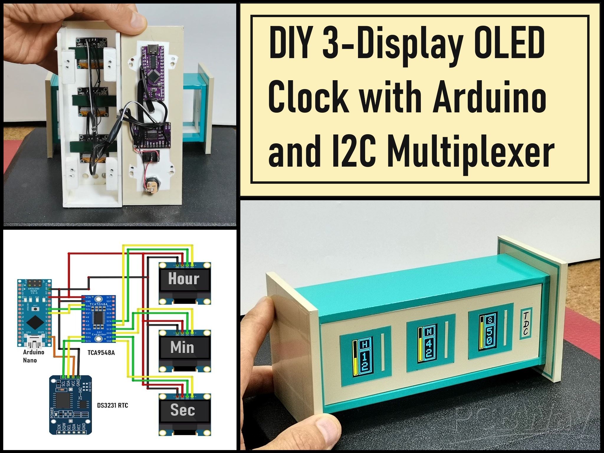
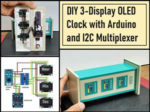
DIY 3-Display OLED Clock with Arduino and I2C Multiplexer
In this video I want to present you another unusual clock to add to my large collection of such DIY devices. Characteristic for this project is the fact that are used three displays on which appears different content.
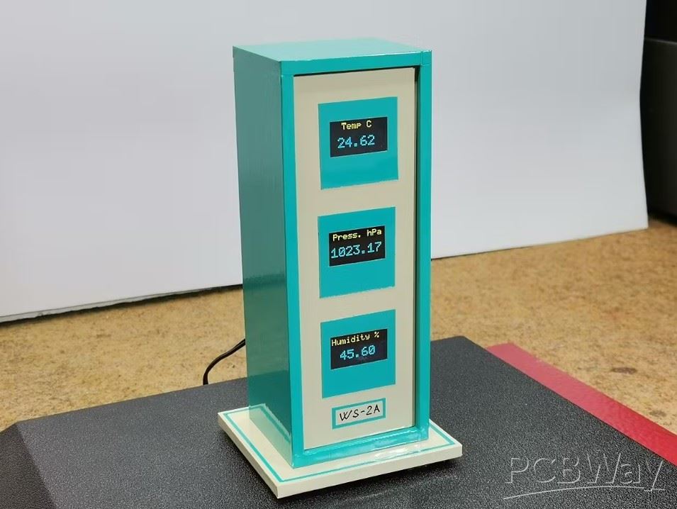
The three displays are with I2C communication protocol and are controlled by a single microcontroller, but with the help of an I2C multiplexer module. I used similar hardware in one of my previous projects , but now instead of a BME280 module I use a Real Time Clock module.
The device is really simple to operate and consists of only a few components:
- LGT8F328P microcontroller board (here I would like to emphasize that without any changes in the code in the project, you can use Arduino Nano or Arduino UNO board)
- TCA9548A I2C multiplexer module
- Three OLED displays SSD1306 (Specifically in this project I am using a Blue-Yellow display, but another color or combination of colors can be used without modification.)
- and DS3231 Realtime clock module
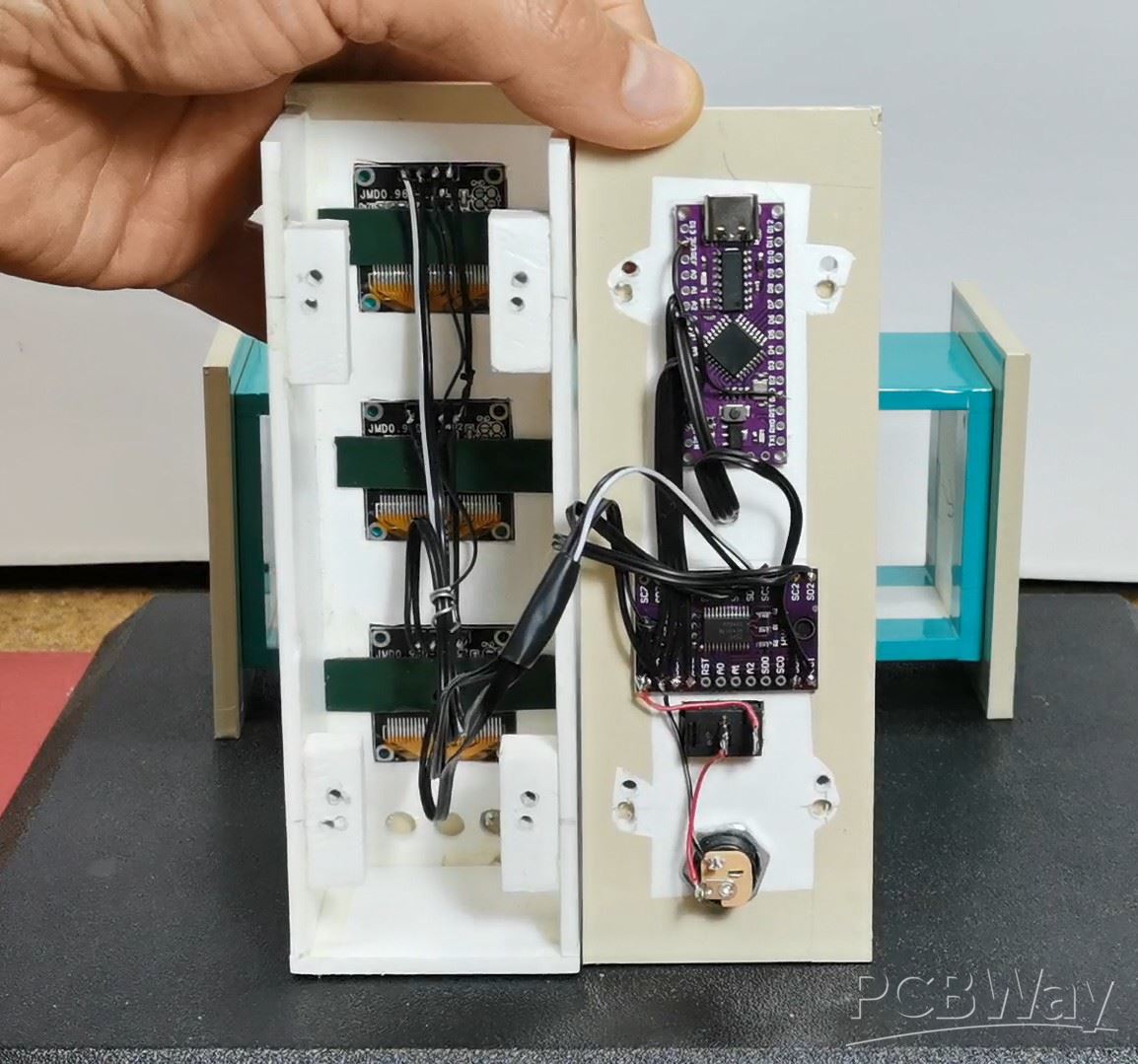
This time I also use the case from the previous project, which, unlike then, is now placed in a horizontal position.
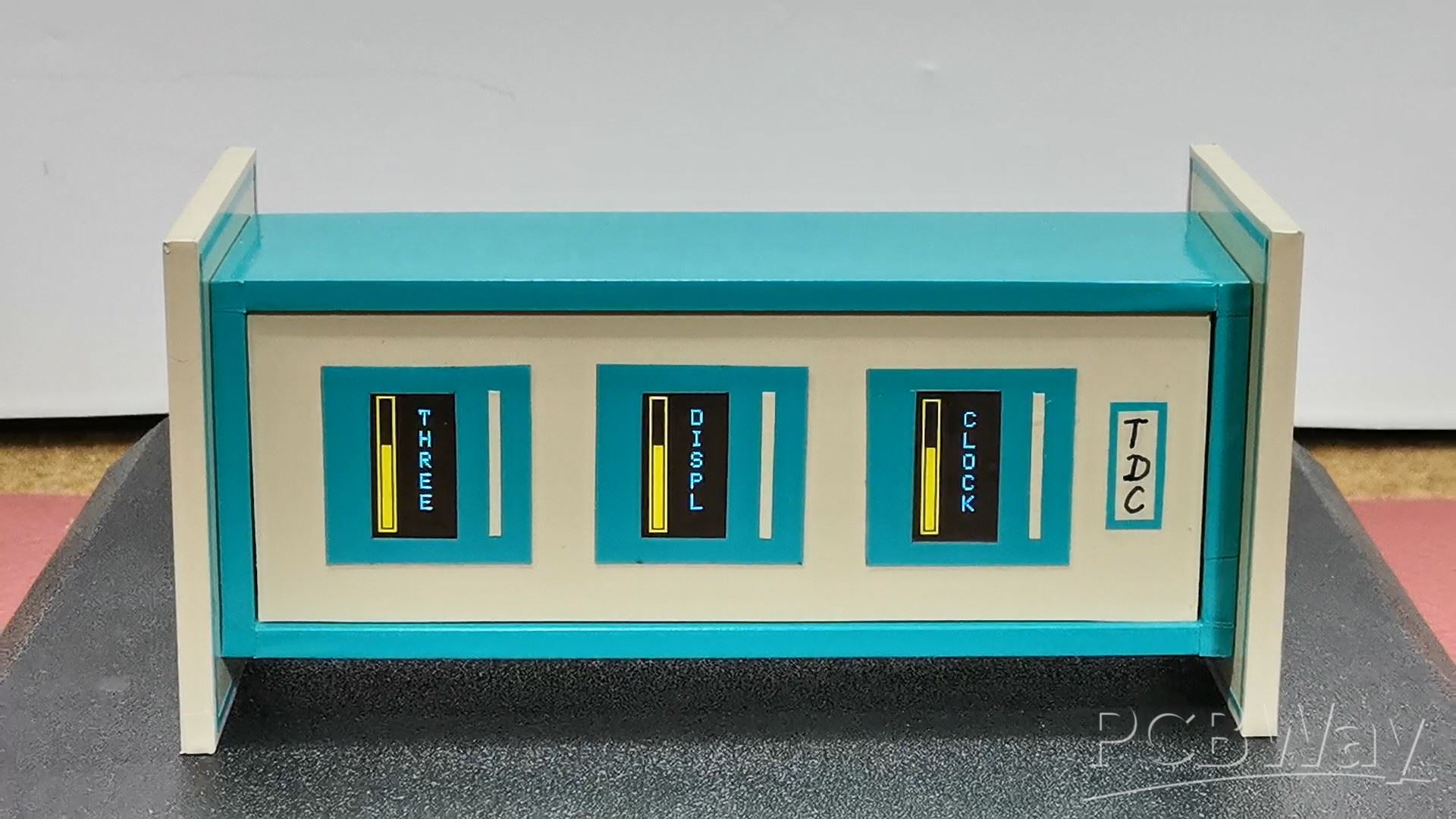
Now I propose to see how the clock works in real conditions. After switching on, the text "three display clock" appears sequentially on the three displays, an appropriate animation when writing the text, as well as rising and falling bars on the sides. Let's see how it works.
After this, the clock starts working. On the first display, in the blue field, the hour is displayed, on the second the minutes and on the third the seconds, which are marked on the top with "H", "M" and "S". On the bottom blue part the tens are displayed and below them the units respectively.
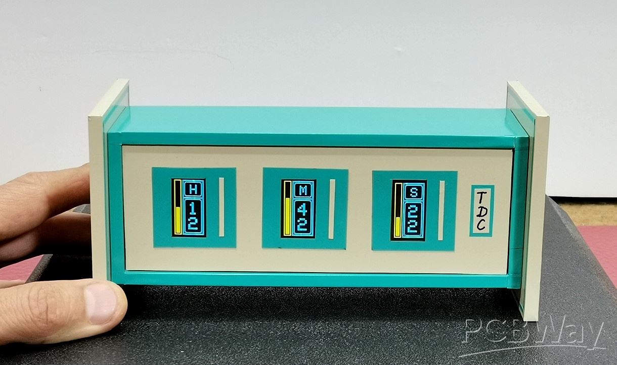
On the left yellow part of the screen there are three bars. The first one displays the elapsed time of the current Day in Hours (from 0 to 24), then the second one displays the elapsed time of the current Hour in Minutes (from 0 to 60 minutes), and similarly the third bar displays the elapsed time of the current Minute in Seconds (also from 0 to 60). Unfortunately, on video it's hard to capture the original image, which is crystal clear and without any flickering.
Let me mention that the exact time is downloaded from the personal computer automatically when uploading the code, but there is also an option to enter it into the code yourself.
And now a few words about the code.
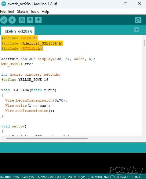
It is relatively simple and uses only two libraries, one is support for OLED displays, and the other controls the Realtime Clock module.
At the beginning, the three displays are initialized and the exact time is downloaded from the PC. Then we have the showIntro function, which is intended for displaying the intro at the beginning. And finally the basic drawDisplay function, which draws the content of the three displays. Here we can easily change the parameters such as the font, size and borders, so the visual part of the clock can be easily modified.
And finally a short conclusion. This DIY clock successfully uses an I2C multiplexer to show the time across three OLED displays, complete with clever progress bars that visually track the elapsed time for the current minute, hour, and day. Code can be easy modified to customize the visual look of the OLED screens.
#include <Wire.h>
#include <Adafruit_SSD1306.h>
#include <RTClib.h>

Adafruit_SSD1306 display(128, 64, &Wire, 4);
RTC_DS3231 rtc;

int hours, minutes, seconds;
#define YELLOW_ZONE 16

void TCA9548A(uint8_t bus)
{
  Wire.beginTransmission(0x70);
  Wire.write(1 << bus);
  Wire.endTransmission();
}

void setup()
{
  // Initialize RTC on channel 1
  TCA9548A(1);
  rtc.begin();

  if (rtc.lostPower()) {
    rtc.adjust(DateTime(F(__DATE__), F(__TIME__)));
  }

    // --- OPTIONAL MANUAL TIME SET (only enable when needed) ---
  // To set time manually, remove the comment marks from the lines below,
  // adjust the DateTime parameters (Year, Month, Day, Hour, Minute, Second),
  // upload once, then comment them out again to prevent overwriting the RTC each boot.

 // rtc.adjust(DateTime(2025, 10, 22, 12, 15, 00));  // YYYY, MM, DD, HH, MM, SS


  // Initialize displays with rotated orientation
  // Display 1: Seconds (leftmost) - Channel 2
  TCA9548A(2);
  display.begin(SSD1306_SWITCHCAPVCC, 0x3C);
  display.setRotation(1); // Rotate 90 degrees for portrait mode
  display.clearDisplay();
  display.display();

  // Display 2: Minutes (middle) - Channel 3
  TCA9548A(3);
  display.begin(SSD1306_SWITCHCAPVCC, 0x3C);
  display.setRotation(1); // Rotate 90 degrees for portrait mode
  display.clearDisplay();
  display.display();

  // Display 3: Hours (rightmost) - Channel 4
  TCA9548A(4);
  display.begin(SSD1306_SWITCHCAPVCC, 0x3C);
  display.setRotation(1); // Rotate 90 degrees for portrait mode
  display.clearDisplay();
  display.display();

   delay(500);
  showIntro();

 // delay(1000);
}

void showIntro() {
  int screenH = 128;
  const char* words[3] = {"CLOCK", "DISPL", "THREE"};

  // --- STEP 1: Loading animation + falling letters ---
  for (int h = 0; h <= 120; h += 6) {
    for (int idx = 0; idx < 3; idx++) {
      int ch = 2 + idx;
      TCA9548A(ch);
      display.clearDisplay();

      // --- Yellow frame (16x128, 2-px border) ---
      for (int i = 0; i < 2; i++) {
        display.drawRect(i, i, YELLOW_ZONE - 2 * i, screenH - 2 * i, WHITE);
      }

      // --- Filling bar ---
      int fillX = 4;
      int fillW = YELLOW_ZONE - 8;
      int fillY = 124 - h;
      display.fillRect(fillX, fillY, fillW, h, WHITE);

      // --- Falling letters ---
      display.setTextColor(WHITE);
      display.setTextSize(2);
      int textX = YELLOW_ZONE + 20;
      int textY = 12;
      const char* w = words[idx];

      // Determine how many letters to show depending on progress
      int totalLetters = strlen(w);
      int visibleLetters = map(h, 0, 120, 0, totalLetters);
      if (visibleLetters > totalLetters) visibleLetters = totalLetters;

      // Draw visible letters vertically, one by one
      for (int k = 0; k < visibleLetters; k++) {
        display.setCursor(textX, textY + k * 20);
        display.write(w[k]);
      }

      display.display();
    }
    delay(80);
  }

  delay(1000); // pause 1 s at full bar

  // --- STEP 2: Fade-out animation (bars emptying downward) ---
  for (int h = 120; h >= 0; h -= 6) {
    for (int idx = 0; idx < 3; idx++) {
      int ch = 2 + idx;
      TCA9548A(ch);
      display.clearDisplay();

      // --- Yellow frame ---
      for (int i = 0; i < 2; i++) {
        display.drawRect(i, i, YELLOW_ZONE - 2 * i, screenH - 2 * i, WHITE);
      }

      // --- Emptying bar ---
      int fillX = 4;
      int fillW = YELLOW_ZONE - 8;
      int fillY = 124 - h;
      display.fillRect(fillX, fillY, fillW, h, WHITE);

      // --- Keep all letters visible during fade ---
      display.setTextColor(WHITE);
      display.setTextSize(2);
      int textX = YELLOW_ZONE + 20;
      int textY = 12;
      const char* w = words[idx];
      for (int k = 0; w[k]; k++) {
        display.setCursor(textX, textY + k * 20);
        display.write(w[k]);
      }

      display.display();
    }
    delay(60);
  }

  // --- STEP 3: Clear all displays ---
  for (int ch = 2; ch <= 4; ch++) {
    TCA9548A(ch);
    display.clearDisplay();
    display.display();
  }
}

void loop()
{
  // Read time from RTC
  TCA9548A(1);
  DateTime now = rtc.now();
  hours = now.hour();
  minutes = now.minute();
  seconds = now.second();

  // Update Seconds Display (Left) - Channel 2
  TCA9548A(2);
  display.clearDisplay();
  drawDisplay(seconds, 'S', 60, seconds);
  display.display();

  // Update Minute Display (Middle) - Channel 3
  TCA9548A(3);
  display.clearDisplay();
  drawDisplay(minutes, 'M', 60, minutes);
  display.display();

  // Update Hours Display (Right) - Channel 4
  TCA9548A(4);
  display.clearDisplay();
  drawDisplay(hours, 'H', 24, hours);
  display.display();

  delay(200); // Update 5 times per second
}

void drawDisplay(int value, char unit, int maxValue, int barValue) {
  // NOTE: In portrait rotation, display.width() = 64, display.height() = 128
  int screenW = 64;
  int screenH = 128;

  // --- Bargraph container ---
  int barX = 0;
  int barW = YELLOW_ZONE;  // 16 px
  int barY = 0;
  int barH = screenH;

  // Outer rectangle (frame, 2-px thick)
  for (int i = 0; i < 2; i++) {
    display.drawRect(barX + i, barY + i, barW - 2 * i, barH - 2 * i, WHITE);
  }

  // --- Calculate bar height (usable area = 120 px: from y=4 to y=124) ---
  int innerTop = 4;
  int innerBottom = screenH - 4;
  int usableHeight = innerBottom - innerTop;  // 120 px

  int barHeight = map(barValue, 0, maxValue, 0, usableHeight);

  // --- Fill the bar inside the container ---
  int fillX = barX + 2 + 2;        // 2-px frame + 2-px gap
  int fillW = barW - 8;            // 2+2 margin each side → 8 total
  int fillY = innerBottom - barHeight;  // fill upward from bottom
  display.fillRect(fillX, fillY, fillW, barHeight, WHITE);

  // --- Blue field dimensions (right side) ---
  int frameX1 = YELLOW_ZONE;
  int frameW  = screenW - YELLOW_ZONE;
  int frameY1 = 0;
  int frameH  = screenH;

  // --- Outer frame (3 px) ---
  for (int i = 0; i < 3; i++) {
    display.drawRect(frameX1 + i, frameY1 + i, frameW - 2 * i, frameH - 2 * i, WHITE);
  }

  // --- Divider between letter and digits ---
  int dividerY = 40;
  display.fillRect(frameX1 + 3, dividerY, frameW - 6, 3, WHITE);

  // --- Text ---
  display.setTextColor(WHITE);
  display.setTextSize(3);

  // Upper: unit letter (H / M / S)
  int unitX = frameX1 + 17;
  int unitY = 11;
  display.setCursor(unitX, unitY);
  display.print(unit);

  display.setTextSize(4);

  // Lower: digits
  int tens = value / 10;
  int units = value % 10;

  int tensX = frameX1 + 13;
  int tensY = 52;
  display.setCursor(tensX, tensY);
  display.print(tens);

  int unitsX = frameX1 + 13;
  int unitsY = 87;
  display.setCursor(unitsX, unitsY);
  display.print(units);

  // --- Inner rounded frames ---
  // Top rectangle (letters)
  int innerTopX = frameX1 + 4;
  int innerTopY = 4;
  int innerTopW = frameW - 8;
  int innerTopH = dividerY - innerTopY - 2; // 1px gap to divider
  for (int i = 0; i < 2; i++) {
    display.drawRoundRect(innerTopX + i, innerTopY + i, innerTopW - 2 * i, innerTopH - 2 * i, 4, WHITE);
  }

  // Bottom rectangle (digits)
  int innerBotX = frameX1 + 4;
  int innerBotY = dividerY + 4; // 1px gap below divider
  int innerBotW = frameW - 8;
  int innerBotH = frameH - innerBotY - 4;
  for (int i = 0; i < 2; i++) {
    display.drawRoundRect(innerBotX + i, innerBotY + i, innerBotW - 2 * i, innerBotH - 2 * i, 4, WHITE);
  }
}
DIY 3-Display OLED Clock with Arduino and I2C Multiplexer


Raspberry Pi 5 7 Inch Touch Screen IPS 1024x600 HD LCD HDMI-compatible Display for RPI 4B 3B+ OPI 5 AIDA64 PC Secondary Screen(Without Speaker)
BUY NOW


- Comments(1)
- Likes(0)
More by Mirko Pavleski
-
 Arduino 3D Printed self Balancing Cube
Self-balancing devices are electronic devices that use sensors and motors to keep themselves balanc...
Arduino 3D Printed self Balancing Cube
Self-balancing devices are electronic devices that use sensors and motors to keep themselves balanc...
-
 Retro Analog VU Meter on Round dispalys (ESP32 and GC9A01)
Recently, in one of my previous videos I presented you a Retro VU Meter project on round displays ...
Retro Analog VU Meter on Round dispalys (ESP32 and GC9A01)
Recently, in one of my previous videos I presented you a Retro VU Meter project on round displays ...
-
 Ultimate 2-Player Reaction Timer with WS2812B LED Strips & Arduino
Arcade reaction game is a genre of play designed to test a player's physical response time and hand...
Ultimate 2-Player Reaction Timer with WS2812B LED Strips & Arduino
Arcade reaction game is a genre of play designed to test a player's physical response time and hand...
-
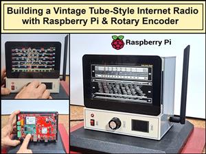 Building a Vintage Tube-Style Internet Radio with Raspberry Pi & Rotary Encoder
Internet radio (also known as web radio or net radio) is a digital audio service transmitted via th...
Building a Vintage Tube-Style Internet Radio with Raspberry Pi & Rotary Encoder
Internet radio (also known as web radio or net radio) is a digital audio service transmitted via th...
-
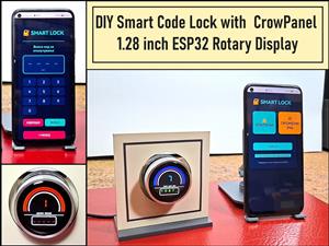 DIY Smart Code Lock with CrowPanel 1.28 ESP32 Rotary Display
A code lock is a keyless security device—either mechanical or electronic—that restricts access to d...
DIY Smart Code Lock with CrowPanel 1.28 ESP32 Rotary Display
A code lock is a keyless security device—either mechanical or electronic—that restricts access to d...
-
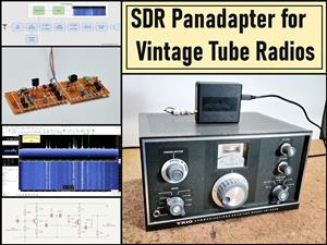 SDR Panadapter for Vintage Tube Radios – Step-by-Step Tutorial
A radio panadapter (or panoramic adapter) is a device or software tool used in amateur radio and ot...
SDR Panadapter for Vintage Tube Radios – Step-by-Step Tutorial
A radio panadapter (or panoramic adapter) is a device or software tool used in amateur radio and ot...
-
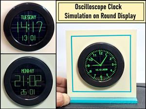 Oscilloscope Clock Simulation on a Round ESP32 Display
An oscilloscope clock is a circuit that turns an old analog oscilloscope into a stylish, retro-them...
Oscilloscope Clock Simulation on a Round ESP32 Display
An oscilloscope clock is a circuit that turns an old analog oscilloscope into a stylish, retro-them...
-
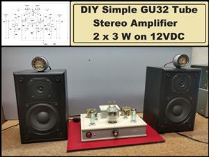 DIY Simple GU32 Tube Stereo Amplifier (2x3W on 12VDC)
Vacuum tube amplifiers are often favored for their smooth harmonic distortion, especially in the low...
DIY Simple GU32 Tube Stereo Amplifier (2x3W on 12VDC)
Vacuum tube amplifiers are often favored for their smooth harmonic distortion, especially in the low...
-
 DIY 3-Display OLED Clock with Arduino and I2C Multiplexer
In this video I want to present you another unusual clock to add to my large collection of such DIY...
DIY 3-Display OLED Clock with Arduino and I2C Multiplexer
In this video I want to present you another unusual clock to add to my large collection of such DIY...
-
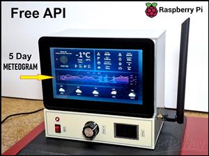 Build a 5-Day forecast Raspberry Pi Weather Dashboard (Step-by-Step)
Recently in one of my previous videos,I introduced you to the 7 inch Elecrow Pi Terminal and how to...
Build a 5-Day forecast Raspberry Pi Weather Dashboard (Step-by-Step)
Recently in one of my previous videos,I introduced you to the 7 inch Elecrow Pi Terminal and how to...
-
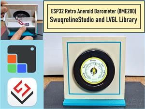 ESP32 Aneroid Barometer using Squareline Studio and LVGL on CrowPanel Round display
A barometer is a scientific instrument used to measure atmospheric pressure. Rising Pressure genera...
ESP32 Aneroid Barometer using Squareline Studio and LVGL on CrowPanel Round display
A barometer is a scientific instrument used to measure atmospheric pressure. Rising Pressure genera...
-
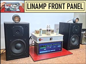 LINAMP Project – Winamp-Style Audio Front Panel on Raspberry Pi 5
Winamp is one of the most iconic and historically significant digital media players ever created. I...
LINAMP Project – Winamp-Style Audio Front Panel on Raspberry Pi 5
Winamp is one of the most iconic and historically significant digital media players ever created. I...
-
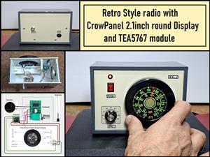 Retro Style radio with CrowPanel 2.1inch round Display (TEA5767)
Some time ago I presented you a clock project with CrowPanel 2.1inch-HMI ESP32 Rotary Display 480*4...
Retro Style radio with CrowPanel 2.1inch round Display (TEA5767)
Some time ago I presented you a clock project with CrowPanel 2.1inch-HMI ESP32 Rotary Display 480*4...
-
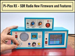 Pi-Pico RX - SDR Radio with New Firmware and Features
A few months ago I presented you a wonderful SDR radio project by DawsonJon 101 Things. In short, i...
Pi-Pico RX - SDR Radio with New Firmware and Features
A few months ago I presented you a wonderful SDR radio project by DawsonJon 101 Things. In short, i...
-
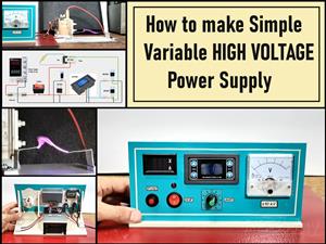 How to make simple Variable HIGH VOLTAGE Power Supply
High Voltage Power Supply is usually understood as a device that is capable of generating a voltage...
How to make simple Variable HIGH VOLTAGE Power Supply
High Voltage Power Supply is usually understood as a device that is capable of generating a voltage...
-
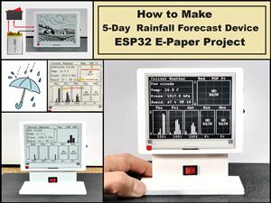 DIY 5-Day Rainfall Forecast Device - ESP32 E-Paper Project
In several of my previous projects I have presented ways to make weather stations, but this time I ...
DIY 5-Day Rainfall Forecast Device - ESP32 E-Paper Project
In several of my previous projects I have presented ways to make weather stations, but this time I ...
-
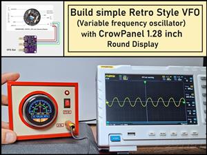 Build simple Retro Style VFO (Variable frequency oscillator) with Crowoanel 1.28 inch Round Display
Today I received a shipment with a Small round LCD display from Elecrow. The device is packed in tw...
Build simple Retro Style VFO (Variable frequency oscillator) with Crowoanel 1.28 inch Round Display
Today I received a shipment with a Small round LCD display from Elecrow. The device is packed in tw...
-
 Human vs Robot – Rock Paper Scissors with MyCobot 280 M5Stack
Today I received a package containing the few Elephant Robotics products. The shipment is well pack...
Human vs Robot – Rock Paper Scissors with MyCobot 280 M5Stack
Today I received a package containing the few Elephant Robotics products. The shipment is well pack...
-
-
ARPS-2 – Arduino-Compatible Robot Project Shield for Arduino UNO
1290 0 4 -
A Compact Charging Breakout Board For Waveshare ESP32-C3
1807 3 7 -
AI-driven LoRa & LLM-enabled Kiosk & Food Delivery System
1795 2 0 -
-
-
-
ESP32-C3 BLE Keyboard - Battery Powered with USB-C Charging
1971 0 1 -


