


|
|
SDRPlay SDR radio |
x 1 | |
|
|
J310 FET |
x 1 | |
|
|
BF199 Transistor |
x 1 | |
|
|
Capacitors, Resistors |
x 1 |

|
Soldering Iron Kit |
|
|
|
SDRPLAY Software |
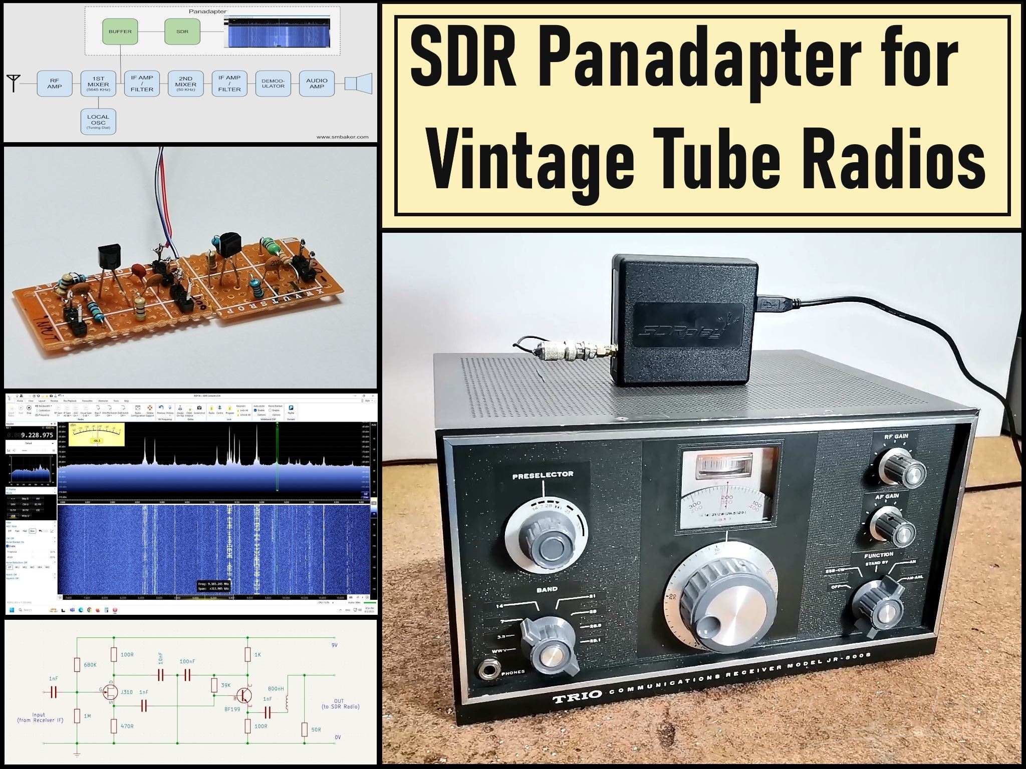
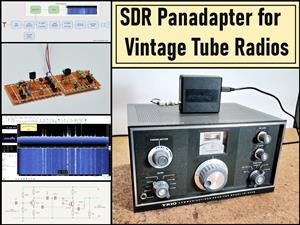
SDR Panadapter for Vintage Tube Radios – Step-by-Step Tutorial
A radio panadapter (or panoramic adapter) is a device or software tool used in amateur radio and other radio communications to display a wideband spectrum view of signals around a selected frequency. It allows operators to visually monitor a range of frequencies in real time, rather than just listening to a single frequency. Panadapter shows a graphical representation of signal strength across a range of frequencies and helps identify active signals, interference, or unused frequencies.
There are generally two types of Panadapters :
- Hardware-Based: Dedicated external devices that connect to a radio's IF output.
- and Software-Based Panadapters that use SDR receivers (like RTL-SDR, SDRplay, or KiwiSDR) to display spectrum data on a computer.
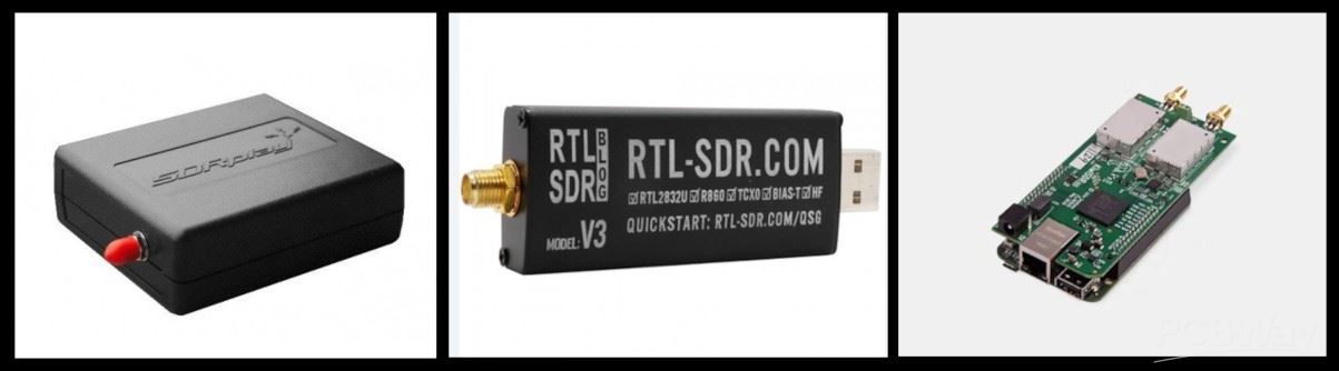
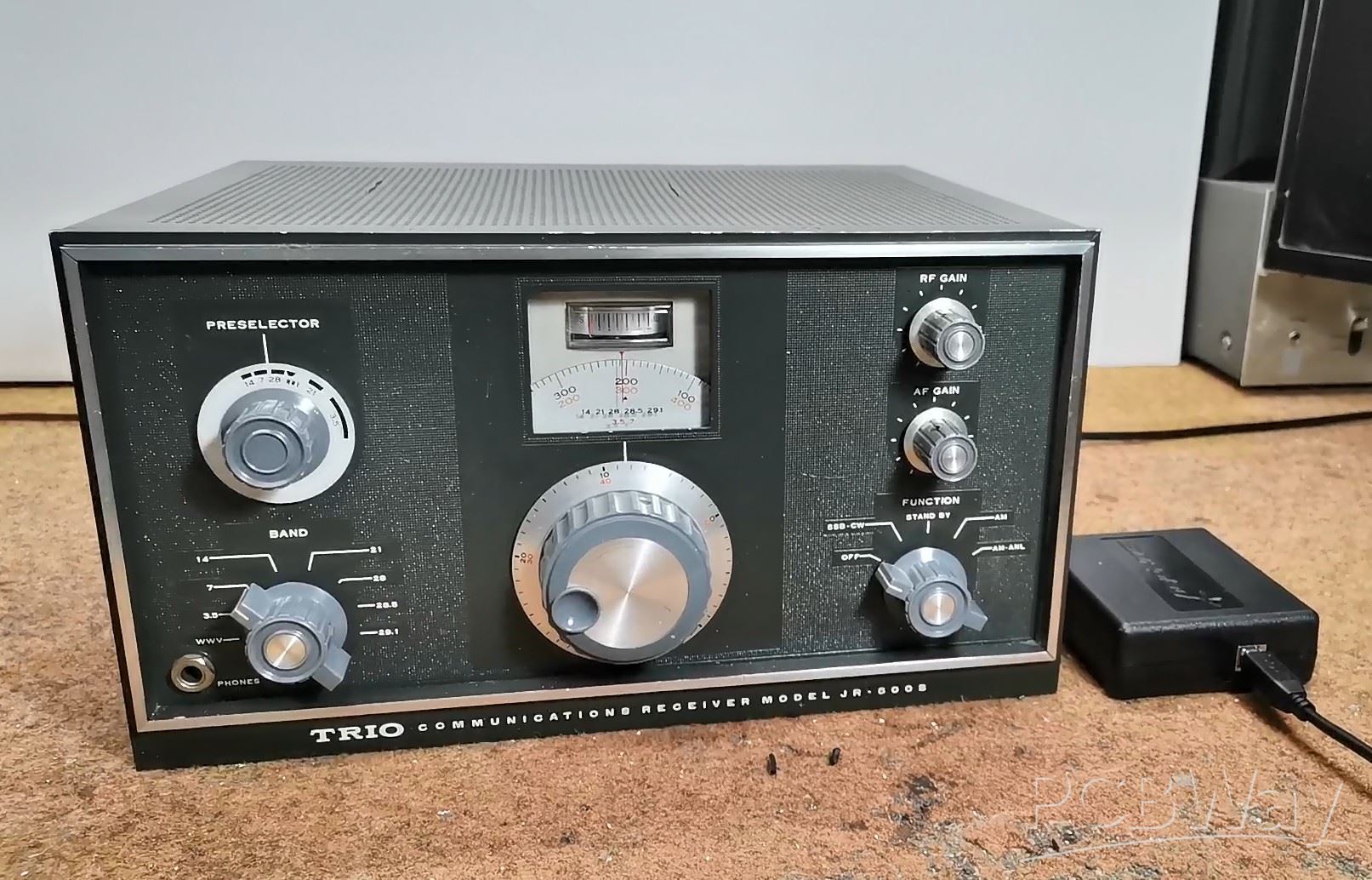
Specifically, in this project, I developed software based Panadapter, using my SDRPlay SDR radio receiver, but as I mentioned earlier, another type of SDR radio can also be used, such as an cheap RTLSDR dongle with appropriate software. This time I decided to modernize my old vacuum tube HF receiver model Trio JR 500S.
This project is sponsored by PCBWay . From concept to production, PCBWay provide cutting-edge electronic design solutions for global innovators, Including hardware design, software development, mechanical design, product testing and certification. PCBWay engineering team consists of experienced engineers in electronics, embedded systems, and product development. They successfully delivered hundreds of projects across industries such as medical devices, industrial automation, consumer electronics, smart home, and IoT.

An excellent explanation of how to install and how the Panadapter works can be found on Scott Baker's website , from where I took the input part of the buffer and some pictures.
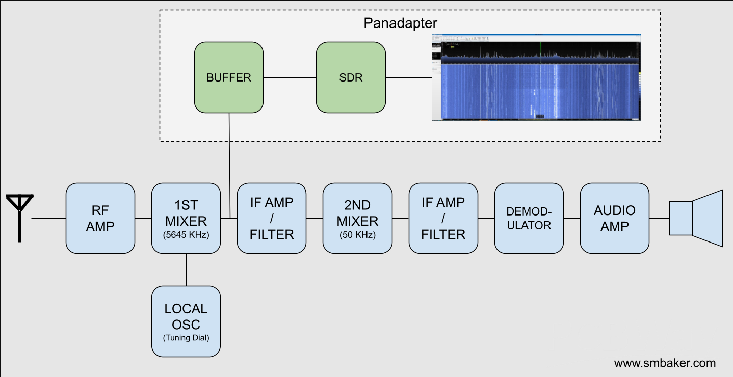
Most old tube and transistor receivers are of the super heterodyne type. The incoming RF signal mixes with a desired frequency from a local oscillator, to center that frequency around an intermediate frequency (IF). In our case, this IF is 8.9 - 9.5 MHz. So we should place the buffer amplifier immediately after the first mixer as shown in the diagram below.
The SDR receiver needs to be able to handle the intermediate frequency from your radio. My Trio JR500S has a 9 MHz intermediate frequency, but your radio may differ. It’s important to notice that the frequency on your SDR receiver will be centered around the IF, in my case 9MHz, wich is no problem for my SDRPlay. Regarding the connection point of the panadapter, this is the schematic of my radio, and the board should be connected immediately after the first IF transformer, i.e. at the point marked with the yellow arrow.
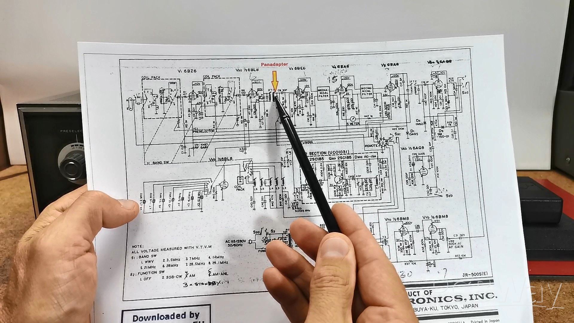
The board should be mounted as close as possible to this point so that there is no additional interference due to the length of the cable. In almost all superheterodyne receivers the panadapter should be connected immediately after the first IF transformer.
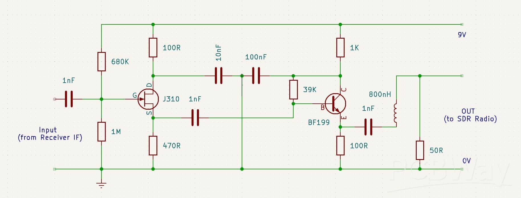
And now a few words about the buffer board. Tube radios are often very high impedance signals. They’re meant to drive loads into the hundreds of kiloohms or even into the megaohms. If you take a regular amplifier designed for a 50 Ohm input impedance, you’ll suck the signal right out of your radio and there will be nothing. You’ll completely load down the receiver. Therefore, the buffer amplifier shown in the diagram below has a very high input impedance, and a low output impedance, so it does not affect the received signal at all. The buffer has two active stages - a JFET source follower to present a high impedance to the IF filter, and therefore minimise any loading on the main signal path of the radio.
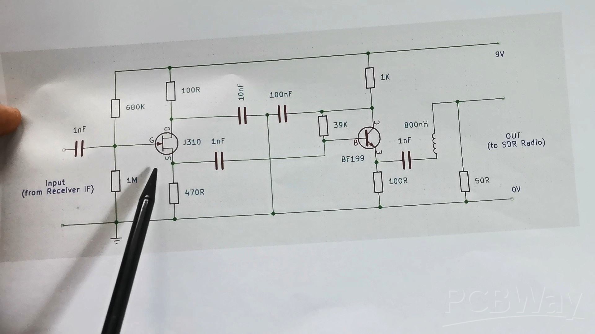
Then followsa BJT Transistor as an emitter follower to provide impedance transformation for a following filter stage. And finally, I added a very simple 10MHz / 3dB Lowpass filter consisting of a single inductor and a resistor.
Here's what the PCB looks like mounted in the radio
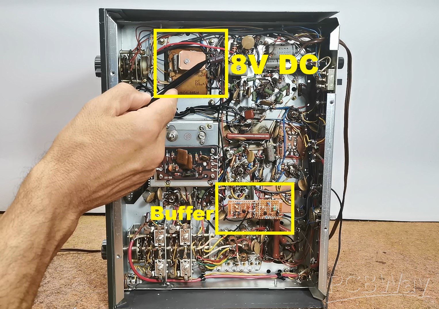
I took power from the mains transformer through a rectifier, and the output signal from the buffer comes out through this hole and should be connected to the Antenna input of the SDR receiver. Now we will look at the signal spectrum of the entire 41m Broadcast band, as well as the 40m Amateur band. In fact, these are the frequencies on which I had the best reception at the time of recording this video. First of all, on the SDR Uno software, we need to set the first IF frequency of the radio receiver, and in this case it is about 9.1 MHz and start SDRUno software. Now, we need to set the preselector knob of the radio to the position where we have the best reception. This is the spectrum of the entire 40m and 41m band.
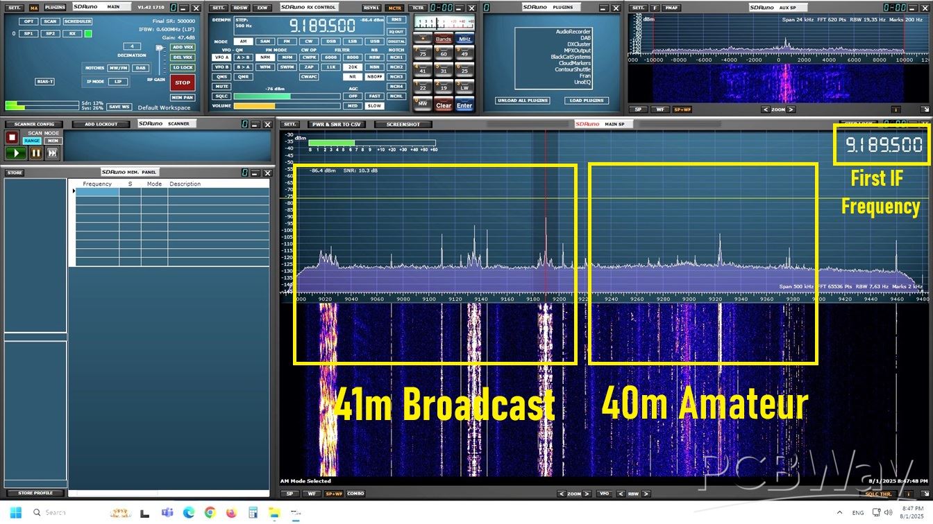
We can select the desired signal, and with the help of the software, we can set many different parameters, which are almost impossible to change directly on the radio hardware. So in this case, we use only the input part of the radio up to the first IF transformer, and then all the electronics of the radio are replaced with the SDRPlay SDR radio and the appropriate software.
And finally a short conclusion. By integrating an SDR-based panadapter into my Trio JR500S, I’ve brought modern spectrum visualization to this classic tube radio. This upgrade enhances functionality while preserving the vintage charm of the receiver. If I now go back to the original tube receiver, we will see that I receive the same stations directly on the receiver, which is confirmation of the fact that the Buffer Amplifier does not affect the original input signal at all.

SDR Panadapter for Vintage Tube Radios – Step-by-Step Tutorial


Raspberry Pi 5 7 Inch Touch Screen IPS 1024x600 HD LCD HDMI-compatible Display for RPI 4B 3B+ OPI 5 AIDA64 PC Secondary Screen(Without Speaker)
BUY NOW


- Comments(1)
- Likes(1)
More by Mirko Pavleski
-
 Arduino 3D Printed self Balancing Cube
Self-balancing devices are electronic devices that use sensors and motors to keep themselves balanc...
Arduino 3D Printed self Balancing Cube
Self-balancing devices are electronic devices that use sensors and motors to keep themselves balanc...
-
 Retro Analog VU Meter on Round dispalys (ESP32 and GC9A01)
Recently, in one of my previous videos I presented you a Retro VU Meter project on round displays ...
Retro Analog VU Meter on Round dispalys (ESP32 and GC9A01)
Recently, in one of my previous videos I presented you a Retro VU Meter project on round displays ...
-
 Ultimate 2-Player Reaction Timer with WS2812B LED Strips & Arduino
Arcade reaction game is a genre of play designed to test a player's physical response time and hand...
Ultimate 2-Player Reaction Timer with WS2812B LED Strips & Arduino
Arcade reaction game is a genre of play designed to test a player's physical response time and hand...
-
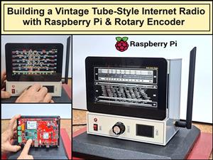 Building a Vintage Tube-Style Internet Radio with Raspberry Pi & Rotary Encoder
Internet radio (also known as web radio or net radio) is a digital audio service transmitted via th...
Building a Vintage Tube-Style Internet Radio with Raspberry Pi & Rotary Encoder
Internet radio (also known as web radio or net radio) is a digital audio service transmitted via th...
-
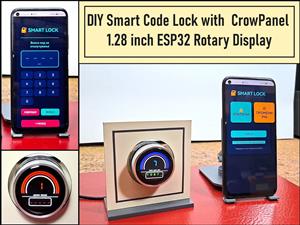 DIY Smart Code Lock with CrowPanel 1.28 ESP32 Rotary Display
A code lock is a keyless security device—either mechanical or electronic—that restricts access to d...
DIY Smart Code Lock with CrowPanel 1.28 ESP32 Rotary Display
A code lock is a keyless security device—either mechanical or electronic—that restricts access to d...
-
 SDR Panadapter for Vintage Tube Radios – Step-by-Step Tutorial
A radio panadapter (or panoramic adapter) is a device or software tool used in amateur radio and ot...
SDR Panadapter for Vintage Tube Radios – Step-by-Step Tutorial
A radio panadapter (or panoramic adapter) is a device or software tool used in amateur radio and ot...
-
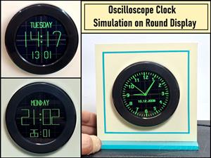 Oscilloscope Clock Simulation on a Round ESP32 Display
An oscilloscope clock is a circuit that turns an old analog oscilloscope into a stylish, retro-them...
Oscilloscope Clock Simulation on a Round ESP32 Display
An oscilloscope clock is a circuit that turns an old analog oscilloscope into a stylish, retro-them...
-
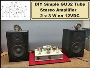 DIY Simple GU32 Tube Stereo Amplifier (2x3W on 12VDC)
Vacuum tube amplifiers are often favored for their smooth harmonic distortion, especially in the low...
DIY Simple GU32 Tube Stereo Amplifier (2x3W on 12VDC)
Vacuum tube amplifiers are often favored for their smooth harmonic distortion, especially in the low...
-
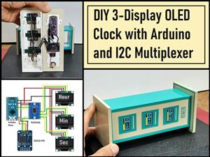 DIY 3-Display OLED Clock with Arduino and I2C Multiplexer
In this video I want to present you another unusual clock to add to my large collection of such DIY...
DIY 3-Display OLED Clock with Arduino and I2C Multiplexer
In this video I want to present you another unusual clock to add to my large collection of such DIY...
-
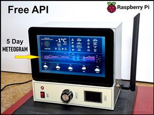 Build a 5-Day forecast Raspberry Pi Weather Dashboard (Step-by-Step)
Recently in one of my previous videos,I introduced you to the 7 inch Elecrow Pi Terminal and how to...
Build a 5-Day forecast Raspberry Pi Weather Dashboard (Step-by-Step)
Recently in one of my previous videos,I introduced you to the 7 inch Elecrow Pi Terminal and how to...
-
 ESP32 Aneroid Barometer using Squareline Studio and LVGL on CrowPanel Round display
A barometer is a scientific instrument used to measure atmospheric pressure. Rising Pressure genera...
ESP32 Aneroid Barometer using Squareline Studio and LVGL on CrowPanel Round display
A barometer is a scientific instrument used to measure atmospheric pressure. Rising Pressure genera...
-
 LINAMP Project – Winamp-Style Audio Front Panel on Raspberry Pi 5
Winamp is one of the most iconic and historically significant digital media players ever created. I...
LINAMP Project – Winamp-Style Audio Front Panel on Raspberry Pi 5
Winamp is one of the most iconic and historically significant digital media players ever created. I...
-
 Retro Style radio with CrowPanel 2.1inch round Display (TEA5767)
Some time ago I presented you a clock project with CrowPanel 2.1inch-HMI ESP32 Rotary Display 480*4...
Retro Style radio with CrowPanel 2.1inch round Display (TEA5767)
Some time ago I presented you a clock project with CrowPanel 2.1inch-HMI ESP32 Rotary Display 480*4...
-
 Pi-Pico RX - SDR Radio with New Firmware and Features
A few months ago I presented you a wonderful SDR radio project by DawsonJon 101 Things. In short, i...
Pi-Pico RX - SDR Radio with New Firmware and Features
A few months ago I presented you a wonderful SDR radio project by DawsonJon 101 Things. In short, i...
-
 How to make simple Variable HIGH VOLTAGE Power Supply
High Voltage Power Supply is usually understood as a device that is capable of generating a voltage...
How to make simple Variable HIGH VOLTAGE Power Supply
High Voltage Power Supply is usually understood as a device that is capable of generating a voltage...
-
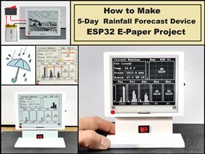 DIY 5-Day Rainfall Forecast Device - ESP32 E-Paper Project
In several of my previous projects I have presented ways to make weather stations, but this time I ...
DIY 5-Day Rainfall Forecast Device - ESP32 E-Paper Project
In several of my previous projects I have presented ways to make weather stations, but this time I ...
-
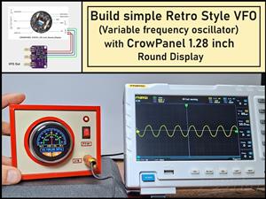 Build simple Retro Style VFO (Variable frequency oscillator) with Crowoanel 1.28 inch Round Display
Today I received a shipment with a Small round LCD display from Elecrow. The device is packed in tw...
Build simple Retro Style VFO (Variable frequency oscillator) with Crowoanel 1.28 inch Round Display
Today I received a shipment with a Small round LCD display from Elecrow. The device is packed in tw...
-
 Human vs Robot – Rock Paper Scissors with MyCobot 280 M5Stack
Today I received a package containing the few Elephant Robotics products. The shipment is well pack...
Human vs Robot – Rock Paper Scissors with MyCobot 280 M5Stack
Today I received a package containing the few Elephant Robotics products. The shipment is well pack...
-
-
ARPS-2 – Arduino-Compatible Robot Project Shield for Arduino UNO
1293 0 4 -
A Compact Charging Breakout Board For Waveshare ESP32-C3
1811 3 7 -
AI-driven LoRa & LLM-enabled Kiosk & Food Delivery System
1802 2 0 -
-
-
-
ESP32-C3 BLE Keyboard - Battery Powered with USB-C Charging
1975 0 1 -


