


|
|
ZK-PP1K PWM generator |
x 1 | |
|
|
MOSFET Switch Driver Module |
x 4 | |
|
|
LEDGeneric
|
x 4 | |
|
|
Through Hole Resistor, 6.8 kohm |
x 4 | |
|
|
Coil |
x 4 | |
|
|
power supply 12V/10A |
x 1 | |
|
|
Rotary potentiometer |
x 1 |

|
Soldering Iron Kit |
How to make Multichannel PEMF Therapy device for PEMF Bed
PEMF therapy, or Pulsed Electromagnetic Field therapy, is a type of therapy that uses electromagnetic fields to promote health and well-being. PEMF therapy is based on the idea that electromagnetic fields can influence the cells and tissues in our bodies. Exposure to these pulsating fields can stimulate cellular activity, improve circulation, reduce inflammation, enhance tissue repair, and support overall healing processes. This therapy has been used for various purposes, including
- pain management,
- promoting bone healing,
- improving sleep quality,
- reducing inflammation,
- enhancing wound healing,
- reducing the effects of stress,
- Improving blood oxygenation, and much more.

In several of my previous videos, which you can view in the given Playlist , are described several simple ways of making such devices.
This time I will describe a simple way to make a multi-channel PEMF device that is used to make a special therapeutic bed, or therapeutic chair.
In this case, the coils are placed inside the mattress, usually distributed in three to four different places, so that when we lie down or sit down, the whole body is exposed to magnetic radiation.

The device is very simple to build, and contains components that are easily available online and are also very inexpensive. The electronic part without coils and power supply costs about $10 total. I used ready-made modules for construction, so it can be made relatively easily by builders who do not have extensive knowledge in this area.

The device contains several components
- ZK-PP1K signal generator module,
- High-Power MOSFET Switch Driver Module, one for each channel,
- 4 Coils,
- and power supply 12V / minimum 10A (power supply from PC can be used for this purpose)

The modules are interconnected with a conductor with a diameter of 1.5 mm or more, due to the large current that passes through them, while the diameter of the wire for the pulsating signal that is brought to their inputs is not important. I am using a 12V/4A power supply for this demonstration because I am only connecting one coil at a time. In real conditions, all four channels would be used, and it is cheaper and more practical to use a PC power supply.
At the output of each channel, I placed an LED diode that signals whether the channel is functioning. These diodes can be freely omitted. In the appendix at the end you can see that there are two similar circuits. In one, a potentiometer has been added, which can be used to continuously regulate the flux from zero to maximum. In my practical device, I have omitted the potentiometer for simplicity, and the intensity of the magnetic field can be partially changed by changing the duty cycle in the range of 5 to 30 percent. Otherwise, the standard value of the duty cycle should be around 10 percent.
I would like to suggest a very important note. Namely, very often on my channel I receive requests for advice on how to make a PEMF device that would output a very strong magnetic flux of 200 Gauss and much more. According to NASA's extensive research in this therapeutic method, the best results are obtained at magnetic flux strengths in the range of 0.5 to 4 Gauss. By increasing the strength of the flux, the effect of the therapy remains unchanged. So the rule "stronger magnetic field - stronger therapy" does not apply here. In this device, the magnetic flux strength is between 10 and 20 Gauss per channel, which is more than enough.
Also various "Exotic" coil shapes with "Magical" properties are definitely a scam and avoid even reading about them at all.

I still can't believe that they are sold at fantastic high prices. Unfortunately, it is a fact that there is a great demand for this type of coils, but only by people who do not understand the way this therapy works. Sellers invent countless silly theories to try to convince you of the effectiveness of their product.
We can test the functionality of this device, as well as other such devices, using an ordinary magnet. If we bring the magnet closer to the coil and if the device works, we should feel vibrations with a frequency set by the signal generator module.
And now a few sentences about making the coils. Coils should meet several conditions:
- The ohmic resistance of the coil (that is the resistance value measured with a standard ohmmeter) should be 4 Ohms or more. At higher resistance, the field is weaker and vice versa.
- The diameter of the wire with which the coil is wound should be greater than 0.5mm (cross-sectional area 0.2mm^2).
- The inductance of the coil is not critical and should be in the range of approximately 10 to 40 mH
- The dimensions of the coil are arbitrary:
A coil with a smaller diameter gives a stronger magnetic field, but over a smaller area, and a coil with a larger cross-section gives a weaker magnetic field over a larger area.
- You can easily make the necessary calculations for sizing the coil using online calculators, and for example I use the(given calculators) following:
https://www.omnicalculator.com/physics/wire-resistance
https://www.eeweb.com/tools/coil-inductance/

And finally, a short conclusion: I am not a medical person and I can not discuss the effect of the device, although I personally have many positive experiences from using it. I can also say with certainty that low frequency magnetic fields definitely have no negative impact, except in people where it is contraindicated(Pregnancy, Pacemakers, bleeding, Active tuberculosis, Malignancies). In fact, MRI imaging uses magnetic fields that are thousands of times stronger than those at PEMF and we all know that this imaging is completely harmless. It is always advisable to consult with a healthcare professional or a qualified practitioner before starting any new therapeutic intervention.
The device is installed in a suitable box made of PVC material with a thickness of 3 and 5 mm and covered with self-adhesive wallpaper


How to make Multichannel PEMF Therapy device for PEMF Bed


Raspberry Pi 5 7 Inch Touch Screen IPS 1024x600 HD LCD HDMI-compatible Display for RPI 4B 3B+ OPI 5 AIDA64 PC Secondary Screen(Without Speaker)
BUY NOW


- Comments(0)
- Likes(0)
More by Mirko Pavleski
-
 Arduino 3D Printed self Balancing Cube
Self-balancing devices are electronic devices that use sensors and motors to keep themselves balanc...
Arduino 3D Printed self Balancing Cube
Self-balancing devices are electronic devices that use sensors and motors to keep themselves balanc...
-
 DIY Avionics Simulator with ESP32 - Artificial Horizon, Compass & Altimeter
The inspiration for this project comes from classical aircraft cockpit instruments used for navigat...
DIY Avionics Simulator with ESP32 - Artificial Horizon, Compass & Altimeter
The inspiration for this project comes from classical aircraft cockpit instruments used for navigat...
-
 DIY Miniature X-Ray Machine using a TV Vacuum Tube DY86
An X-ray machine (or radiograph) is a quick, painless medical test that produces images of the struc...
DIY Miniature X-Ray Machine using a TV Vacuum Tube DY86
An X-ray machine (or radiograph) is a quick, painless medical test that produces images of the struc...
-
 Simple SDR Receiver Using 2x NE612 - Dual Conversion, Superheterodyne (0.1–30 MHz)
SDR (Software Defined Radio) is a radio system in which most of the functions of a classic radio (f...
Simple SDR Receiver Using 2x NE612 - Dual Conversion, Superheterodyne (0.1–30 MHz)
SDR (Software Defined Radio) is a radio system in which most of the functions of a classic radio (f...
-
 DIY Vintage TV VU Meter with peak indicators
Some time ago in one of my projects I presented you a way to turn a black and white old mini TV int...
DIY Vintage TV VU Meter with peak indicators
Some time ago in one of my projects I presented you a way to turn a black and white old mini TV int...
-
 DIY Tesla Coil based Plasma Rife Machine
In several of my previous videos, I presented you with different ways to make a Rife Machine, from ...
DIY Tesla Coil based Plasma Rife Machine
In several of my previous videos, I presented you with different ways to make a Rife Machine, from ...
-
 ESP32 Analog VU Meter – Smooth Needle, Real Audio Response (DIY Build)
In several of my previous videos I have shown you how to make analog VU meters emulated on differen...
ESP32 Analog VU Meter – Smooth Needle, Real Audio Response (DIY Build)
In several of my previous videos I have shown you how to make analog VU meters emulated on differen...
-
 The Ultimate Smartphone VFO ESP32 & Si5351 Wireless Control
Variable frequency oscillators (VFOs) are commonly used in radio transmitters and receivers, especi...
The Ultimate Smartphone VFO ESP32 & Si5351 Wireless Control
Variable frequency oscillators (VFOs) are commonly used in radio transmitters and receivers, especi...
-
 DIY Shortwave Propagation Monitor - Measure Ionosphere Conditions
Shortwave Propagation is the way radio waves in the 3 to 30 MHz range travel from point A to point ...
DIY Shortwave Propagation Monitor - Measure Ionosphere Conditions
Shortwave Propagation is the way radio waves in the 3 to 30 MHz range travel from point A to point ...
-
 Professional grade Smart Lock with ESP32, BLE and Android App Control
An electronic codelock is a security device that grants access using a numerical sequence—a PIN cod...
Professional grade Smart Lock with ESP32, BLE and Android App Control
An electronic codelock is a security device that grants access using a numerical sequence—a PIN cod...
-
 Building a 3-Input Stereo ECC83 (12AX7) Tube Preamp
Some time ago I presented you a project for a 3W stereo tube amplifier with a GU32 output vacuum t...
Building a 3-Input Stereo ECC83 (12AX7) Tube Preamp
Some time ago I presented you a project for a 3W stereo tube amplifier with a GU32 output vacuum t...
-
 ESP32 Weather Dashboard with Satellite Maps and 16-day Weather Forecast
As you can see from my previous videos, besides Electronics, my fields of experimentation and proje...
ESP32 Weather Dashboard with Satellite Maps and 16-day Weather Forecast
As you can see from my previous videos, besides Electronics, my fields of experimentation and proje...
-
 Retro Analog VU Meter on Round dispalys (ESP32 and GC9A01)
Recently, in one of my previous videos I presented you a Retro VU Meter project on round displays ...
Retro Analog VU Meter on Round dispalys (ESP32 and GC9A01)
Recently, in one of my previous videos I presented you a Retro VU Meter project on round displays ...
-
 Ultimate 2-Player Reaction Timer with WS2812B LED Strips & Arduino
Arcade reaction game is a genre of play designed to test a player's physical response time and hand...
Ultimate 2-Player Reaction Timer with WS2812B LED Strips & Arduino
Arcade reaction game is a genre of play designed to test a player's physical response time and hand...
-
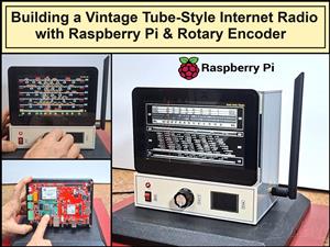 Building a Vintage Tube-Style Internet Radio with Raspberry Pi & Rotary Encoder
Internet radio (also known as web radio or net radio) is a digital audio service transmitted via th...
Building a Vintage Tube-Style Internet Radio with Raspberry Pi & Rotary Encoder
Internet radio (also known as web radio or net radio) is a digital audio service transmitted via th...
-
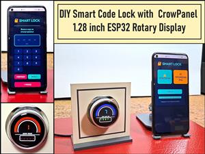 DIY Smart Code Lock with CrowPanel 1.28 ESP32 Rotary Display
A code lock is a keyless security device—either mechanical or electronic—that restricts access to d...
DIY Smart Code Lock with CrowPanel 1.28 ESP32 Rotary Display
A code lock is a keyless security device—either mechanical or electronic—that restricts access to d...
-
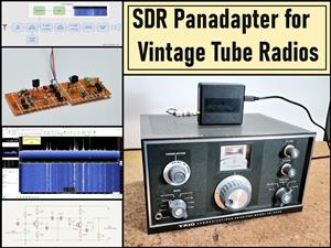 SDR Panadapter for Vintage Tube Radios – Step-by-Step Tutorial
A radio panadapter (or panoramic adapter) is a device or software tool used in amateur radio and ot...
SDR Panadapter for Vintage Tube Radios – Step-by-Step Tutorial
A radio panadapter (or panoramic adapter) is a device or software tool used in amateur radio and ot...
-
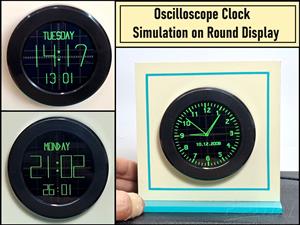 Oscilloscope Clock Simulation on a Round ESP32 Display
An oscilloscope clock is a circuit that turns an old analog oscilloscope into a stylish, retro-them...
Oscilloscope Clock Simulation on a Round ESP32 Display
An oscilloscope clock is a circuit that turns an old analog oscilloscope into a stylish, retro-them...
-
Programmable Mist Maker - XIAO / QT PY Extension
404 0 0 -
RadioHAT - Raspberry Pi radio development platform
316 0 1 -
-
-
-
-
ARPS-2 – Arduino-Compatible Robot Project Shield for Arduino UNO
2867 0 6 -
A Compact Charging Breakout Board For Waveshare ESP32-C3
3370 3 8 -
AI-driven LoRa & LLM-enabled Kiosk & Food Delivery System
3689 2 2


