


|
|
Tesla coil Driver Board |
x 1 | |
|
|
Primary coil |
x 1 | |
|
|
Secondary coil |
x 1 | |
|
|
12V 5A Power Supply |
x 1 |

|
Soldering Iron Kit |
Exploring the Tesla Coil Driver Board, Full Review & Test Results
Some time ago I presented you a video in which I analyzed a super cheap Tesla Coil driver that cost less than $20. This time I will also present you a relatively cheap other type of driver that costs about $50, but is complete and contains a half-bridge circuit with two power mosfets with appropriate heat sinks, as well as a full-wave rectifier.

In short, in this case I only need the coils, the primary and the secondary to assemble a functional Tesla Coil. In this particular example, I'm using a factory-made primary and secondary coil with top load, so it only took me a few minutes to get the device up and running.
First, let's examine the board itself and the elements on it. It is immediately clear that it is quality made on a double-sided laminated PCB. It has the low-voltage part, which is separated from the high-voltage part by white border.

Unlike the previously mentioned module, in this case SMD components are used, which reduces the required board space and cost, and also simplifies the manufacturing process. Low voltage part is powered by an external 12V DC source. Switch selects the operating mode between interrupted or audio modulated. Componets used in interrupter and audio modulator part are two 555 timer ICs, LM393 comparator, and a 74HC14. With the two potentiometers, independent pulse width and frequency can be adjusted in interrupter mode.

This project is sponsored by PCBWay. They has all the services you need to create your project at the best price, whether is a scool project, or complex professional project. On PCBWay you can share your experiences, or get inspiration for your next project. They also provide completed Surface mount SMT PCB assemblY service at a best price, and ISO9001 quality control. Visit pcbway.com for more services.

In music mode only the pulse width can be adjusted, because the frequency is controlled by the music. The small magnetic loop feedbacks the ground wire of the secondary coil. Depending on the direction of the wire, the position of this miniature switch changes. The other part consists of a UCC 37324 dual channel gate driver chip, followed by two complementary MOSFETs of the AO4606 type. In this way, overloading of the gate driver chip is avoided. There is a gate driver transformer to which are connected two power MOSFETs of the type W20NM60, mounted on relatively massive heat sinks, which in terms of characteristics correspond to the well-known IRFP460. The high-voltage section consists of a fuse, a Gretz bridge, and a filter capacitor with a large capacity of 220 microfarads, providing power for the half-bridge MOSFET configuration. The primary winding of the Tesla coil is connected to green terminal, and on other terminal a voltage of maximum 220V. Before I start testing, let me warn you that this experiment will use high voltages that are dangerous to life and health, so I do not recommend repeating it at home unless you have extensive prior knowledge in this area. According to the manufacturer's recommendations, the inductance of the primary coil is recommended to be at least about 7uH, and the resonant frequency of the secondary to range between 200 and 800 Kilohertz.

Specifically in this case, the inductance of this primary coil is 7µH, which is the minimum allowed value, in order to obtain the best possible results. The secondary has a resonant frequency of about 240KHz (about 1200 turns on 7cm diameter body) calculated together with the top load. Now let's see how this device works in real conditions. First we connect the primary coil to the appropriate place, then we pass the beginning of the secondary through this magnetic loop, then to ground. Then we connect a 12V DC source to the appropriate connector, and finally a mains power supply which is good to connect via a variac if you have one. We set the switch to interrupter mode. Now gradually increase the voltage to approximately 50 volts. I bring the CFL bulb closer to the secondary, and if it does not light up, we need to switch the micro switch to the other position.

The lamp should be activated and this is a sign that everything is well connected, and I can start increasing the voltage.

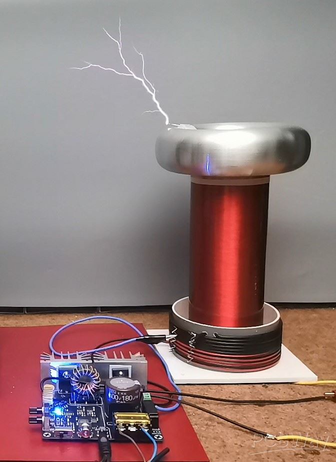

As you can see, the spark is wild with a variable shape, similar to a spark gap Tesla coil, which is a result of the low resonant frequency of the secondary. The length of the spark is slightly more than 12cm, which corresponds to the description of the manufacturer of this driver. It is surprising that the temperature of the power MOSFETs is very low even after long-term operation of the device, which is due to the short duration of the pulse generated by the interrupter.

It also works quite solidly in music mode where square wave music playback is supported

And finally, a short conclusion. This is a relatively cheap complete Tesla coil driver, so we only need a primary and secondary coil, and in a few minutes we can make a good, powerful, functional Tesla coil, suitable for long-term continuous operation.
SAFETY NOTE: Please do not attempt to recreate the experiments shown on this video unless you are familiar with High Voltage Safety Techniques! Direct Current even above 60V maybe lethal, even when the AC supply voltage has been disconnected due to the stored energy in the capacitors.
Exploring the Tesla Coil Driver Board, Full Review & Test Results


Raspberry Pi 5 7 Inch Touch Screen IPS 1024x600 HD LCD HDMI-compatible Display for RPI 4B 3B+ OPI 5 AIDA64 PC Secondary Screen(Without Speaker)
BUY NOW


- Comments(0)
- Likes(1)
More by Mirko Pavleski
-
 Arduino 3D Printed self Balancing Cube
Self-balancing devices are electronic devices that use sensors and motors to keep themselves balanc...
Arduino 3D Printed self Balancing Cube
Self-balancing devices are electronic devices that use sensors and motors to keep themselves balanc...
-
 DIY Avionics Simulator with ESP32 - Artificial Horizon, Compass & Altimeter
The inspiration for this project comes from classical aircraft cockpit instruments used for navigat...
DIY Avionics Simulator with ESP32 - Artificial Horizon, Compass & Altimeter
The inspiration for this project comes from classical aircraft cockpit instruments used for navigat...
-
 DIY Miniature X-Ray Machine using a TV Vacuum Tube DY86
An X-ray machine (or radiograph) is a quick, painless medical test that produces images of the struc...
DIY Miniature X-Ray Machine using a TV Vacuum Tube DY86
An X-ray machine (or radiograph) is a quick, painless medical test that produces images of the struc...
-
 Simple SDR Receiver Using 2x NE612 - Dual Conversion, Superheterodyne (0.1–30 MHz)
SDR (Software Defined Radio) is a radio system in which most of the functions of a classic radio (f...
Simple SDR Receiver Using 2x NE612 - Dual Conversion, Superheterodyne (0.1–30 MHz)
SDR (Software Defined Radio) is a radio system in which most of the functions of a classic radio (f...
-
 DIY Vintage TV VU Meter with peak indicators
Some time ago in one of my projects I presented you a way to turn a black and white old mini TV int...
DIY Vintage TV VU Meter with peak indicators
Some time ago in one of my projects I presented you a way to turn a black and white old mini TV int...
-
 DIY Tesla Coil based Plasma Rife Machine
In several of my previous videos, I presented you with different ways to make a Rife Machine, from ...
DIY Tesla Coil based Plasma Rife Machine
In several of my previous videos, I presented you with different ways to make a Rife Machine, from ...
-
 ESP32 Analog VU Meter – Smooth Needle, Real Audio Response (DIY Build)
In several of my previous videos I have shown you how to make analog VU meters emulated on differen...
ESP32 Analog VU Meter – Smooth Needle, Real Audio Response (DIY Build)
In several of my previous videos I have shown you how to make analog VU meters emulated on differen...
-
 The Ultimate Smartphone VFO ESP32 & Si5351 Wireless Control
Variable frequency oscillators (VFOs) are commonly used in radio transmitters and receivers, especi...
The Ultimate Smartphone VFO ESP32 & Si5351 Wireless Control
Variable frequency oscillators (VFOs) are commonly used in radio transmitters and receivers, especi...
-
 DIY Shortwave Propagation Monitor - Measure Ionosphere Conditions
Shortwave Propagation is the way radio waves in the 3 to 30 MHz range travel from point A to point ...
DIY Shortwave Propagation Monitor - Measure Ionosphere Conditions
Shortwave Propagation is the way radio waves in the 3 to 30 MHz range travel from point A to point ...
-
 Professional grade Smart Lock with ESP32, BLE and Android App Control
An electronic codelock is a security device that grants access using a numerical sequence—a PIN cod...
Professional grade Smart Lock with ESP32, BLE and Android App Control
An electronic codelock is a security device that grants access using a numerical sequence—a PIN cod...
-
 Building a 3-Input Stereo ECC83 (12AX7) Tube Preamp
Some time ago I presented you a project for a 3W stereo tube amplifier with a GU32 output vacuum t...
Building a 3-Input Stereo ECC83 (12AX7) Tube Preamp
Some time ago I presented you a project for a 3W stereo tube amplifier with a GU32 output vacuum t...
-
 ESP32 Weather Dashboard with Satellite Maps and 16-day Weather Forecast
As you can see from my previous videos, besides Electronics, my fields of experimentation and proje...
ESP32 Weather Dashboard with Satellite Maps and 16-day Weather Forecast
As you can see from my previous videos, besides Electronics, my fields of experimentation and proje...
-
 Retro Analog VU Meter on Round dispalys (ESP32 and GC9A01)
Recently, in one of my previous videos I presented you a Retro VU Meter project on round displays ...
Retro Analog VU Meter on Round dispalys (ESP32 and GC9A01)
Recently, in one of my previous videos I presented you a Retro VU Meter project on round displays ...
-
 Ultimate 2-Player Reaction Timer with WS2812B LED Strips & Arduino
Arcade reaction game is a genre of play designed to test a player's physical response time and hand...
Ultimate 2-Player Reaction Timer with WS2812B LED Strips & Arduino
Arcade reaction game is a genre of play designed to test a player's physical response time and hand...
-
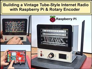 Building a Vintage Tube-Style Internet Radio with Raspberry Pi & Rotary Encoder
Internet radio (also known as web radio or net radio) is a digital audio service transmitted via th...
Building a Vintage Tube-Style Internet Radio with Raspberry Pi & Rotary Encoder
Internet radio (also known as web radio or net radio) is a digital audio service transmitted via th...
-
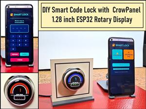 DIY Smart Code Lock with CrowPanel 1.28 ESP32 Rotary Display
A code lock is a keyless security device—either mechanical or electronic—that restricts access to d...
DIY Smart Code Lock with CrowPanel 1.28 ESP32 Rotary Display
A code lock is a keyless security device—either mechanical or electronic—that restricts access to d...
-
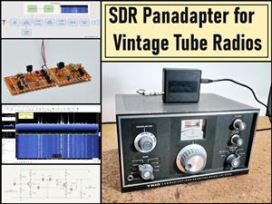 SDR Panadapter for Vintage Tube Radios – Step-by-Step Tutorial
A radio panadapter (or panoramic adapter) is a device or software tool used in amateur radio and ot...
SDR Panadapter for Vintage Tube Radios – Step-by-Step Tutorial
A radio panadapter (or panoramic adapter) is a device or software tool used in amateur radio and ot...
-
 Oscilloscope Clock Simulation on a Round ESP32 Display
An oscilloscope clock is a circuit that turns an old analog oscilloscope into a stylish, retro-them...
Oscilloscope Clock Simulation on a Round ESP32 Display
An oscilloscope clock is a circuit that turns an old analog oscilloscope into a stylish, retro-them...
-
Programmable Mist Maker - XIAO / QT PY Extension
440 0 0 -
RadioHAT - Raspberry Pi radio development platform
342 0 1 -
-
-
-
-
ARPS-2 – Arduino-Compatible Robot Project Shield for Arduino UNO
2894 0 6 -
A Compact Charging Breakout Board For Waveshare ESP32-C3
3394 3 8 -
AI-driven LoRa & LLM-enabled Kiosk & Food Delivery System
3721 2 2


