


|
|
Microwave Oven Trafo |
x 2 | |
|
|
Primary coil |
x 1 | |
|
|
Secondary coil |
x 1 | |
|
|
Spark gap |
x 1 | |
|
|
Topload |
x 1 | |
|
|
HV Capacitor bank |
x 1 | |
|
|
Fluorescent lamp ballast 18W |
x 1 |

|
Soldering Iron Kit |
Dual MOT (microwave oven transformer) Tesla Coil
Tesla coils are known for their ability to generate visually impressive electrical arcs or sparks, making them popular for educational demonstrations, entertainment, and as a hobbyist project. However, more "exotic" parts are required for its construction, among which the HV Transformer is the most difficult to obtain. An old Neon Sign Transformer is often used, but they are difficult to locate in many countries. Likewise, new NSTs are prohibitively expensive for the hobbyist. Alternatives to the neon sign transformers are microwave oven transformers (MOT), because they are universally available for free, or at very low cost from broken microwave ovens.

However, the voltage of their secondary is not sufficient to drive the Spark Gap Tesla Coil. The simplest way to achieve it is to use more than one MOT. Another option is to use some sort of voltage multiplying circuit. It is most practical to use both options, two transformers plus a multiplayer, which is described in this project. In one of my previous videos I described how to make a simplest Spark Gap Tesla coil using an NST transformer. This time I will use the same components from that project, except the high voltage source.
And now let's explain how this type of high voltage source works and is made. I first built it according to Greg's Garage Tesla Coil Site where this schematic is presented, but the multiplayer didn't work.

This project is sponsored by PCBWay. They has all the services you need to create your project at the best price, whether is a scool project, or complex professional project. On PCBWay you can share your experiences, or get inspiration for your next project. They also provide completed Surface mount SMT PCB assemblY service at a best price, and ISO9001 quality control. Visit pcbway.com for more services.

At the very beginning, the part with the diodes connected in series was not clear to me, so I decided to look at the circuit of the simplest so-called Willard half-nave voltage doubler. In our case, we have two such doublers, so analogously to that, it would be logical for the circuit to look like this, that is, the grounding should be connected between the two diodes.

This is the final circuit based on which I built the device.

Basically for the sake of economy I decided to use as many parts as possible from an old microwave oven. In this case, these are transformers, capacitors, and diodes. The primary windings are in parallel connection, and through a suitable fuse are connected to the mains supply. The secondary windings are in series to produce twice the voltage. Let me mention that at MOT one lead of the secondary is always connected to the core of the transformer, in order to avoid the use of expensive insulating material. So the cores are connected to each other, and to the grounding of the device. Capacitors are connected to the other ends, and two diodes are connected in series to them, the middle of which is connected to ground.

In Greg's Scheme, two 100 Ohm 100 Watt resistors and 1nF 10kV capacitors are used in parallel with the diodes that form an RC low-pass filter intended to attenuate any RF feedback from the Tesla coil. These feedback signals can momentarily damage the high voltage diodes. Unfortunately, resistors with such high power are very difficult to obtain, so I successfully use four ballasts from fluorescent tubes instead them wich are actually chokes.

In the following, there is a symmetrical safety gap where the grounding is in the middle, which serves to protect MOTs. With this, the power supply part is ready and we can connect it to the rest of the components of the Tesla Transformer. I will not explain the function of the other components in detail this time, because it is described in the video mentioned above. Now the NST will be replaced by the device described so far. Since the Dual MOT transformer provides a relatively higher current of several hundred milliamps, the capacitor bank should also have a higher value.
Next, let's look at how this Tesla transformer behaves in real conditions:


As you can see in the video, with these components and a short tuning I was able to achieve a spark length of more than 50cm. The fluorescent lamp is lit at a distance from the transformer of 2.5m and more. During the first shots, as a precaution, I did not let the transformer work continuously for more than 20 seconds. Then I tested it with continuous operation for 1 minute and more, so the diodes were completely cold. I only had a problem with excessive heating of the spark gap due to the higher value of the current.
And finally a short conclusion. I am very pleased with the results of this Tesla Coil, although I think with further tuning they would be much better. Especially with increasing the capacitor bank, but unfortunately at the moment I used all the capacitors I had available. I expect a shipment of capacitors to arrive soon, so if there are new results, I will present them to you in one of the following videos.
SAFETY NOTE: Please do not attempt to recreate the experiments shown on this video unless you are familiar with High Voltage Safety Techniques! Direct Current even above 60V maybe lethal, even when the AC supply voltage has been disconnected due to the stored energy in the capacitors. I have no responsibility on any hazards caused by the circuit. Be very careful. This is a humble request.
Dual MOT (microwave oven transformer) Tesla Coil


Raspberry Pi 5 7 Inch Touch Screen IPS 1024x600 HD LCD HDMI-compatible Display for RPI 4B 3B+ OPI 5 AIDA64 PC Secondary Screen(Without Speaker)
BUY NOW


- Comments(0)
- Likes(1)
More by Mirko Pavleski
-
 Arduino 3D Printed self Balancing Cube
Self-balancing devices are electronic devices that use sensors and motors to keep themselves balanc...
Arduino 3D Printed self Balancing Cube
Self-balancing devices are electronic devices that use sensors and motors to keep themselves balanc...
-
 DIY Avionics Simulator with ESP32 - Artificial Horizon, Compass & Altimeter
The inspiration for this project comes from classical aircraft cockpit instruments used for navigat...
DIY Avionics Simulator with ESP32 - Artificial Horizon, Compass & Altimeter
The inspiration for this project comes from classical aircraft cockpit instruments used for navigat...
-
 DIY Miniature X-Ray Machine using a TV Vacuum Tube DY86
An X-ray machine (or radiograph) is a quick, painless medical test that produces images of the struc...
DIY Miniature X-Ray Machine using a TV Vacuum Tube DY86
An X-ray machine (or radiograph) is a quick, painless medical test that produces images of the struc...
-
 Simple SDR Receiver Using 2x NE612 - Dual Conversion, Superheterodyne (0.1–30 MHz)
SDR (Software Defined Radio) is a radio system in which most of the functions of a classic radio (f...
Simple SDR Receiver Using 2x NE612 - Dual Conversion, Superheterodyne (0.1–30 MHz)
SDR (Software Defined Radio) is a radio system in which most of the functions of a classic radio (f...
-
 DIY Vintage TV VU Meter with peak indicators
Some time ago in one of my projects I presented you a way to turn a black and white old mini TV int...
DIY Vintage TV VU Meter with peak indicators
Some time ago in one of my projects I presented you a way to turn a black and white old mini TV int...
-
 DIY Tesla Coil based Plasma Rife Machine
In several of my previous videos, I presented you with different ways to make a Rife Machine, from ...
DIY Tesla Coil based Plasma Rife Machine
In several of my previous videos, I presented you with different ways to make a Rife Machine, from ...
-
 ESP32 Analog VU Meter – Smooth Needle, Real Audio Response (DIY Build)
In several of my previous videos I have shown you how to make analog VU meters emulated on differen...
ESP32 Analog VU Meter – Smooth Needle, Real Audio Response (DIY Build)
In several of my previous videos I have shown you how to make analog VU meters emulated on differen...
-
 The Ultimate Smartphone VFO ESP32 & Si5351 Wireless Control
Variable frequency oscillators (VFOs) are commonly used in radio transmitters and receivers, especi...
The Ultimate Smartphone VFO ESP32 & Si5351 Wireless Control
Variable frequency oscillators (VFOs) are commonly used in radio transmitters and receivers, especi...
-
 DIY Shortwave Propagation Monitor - Measure Ionosphere Conditions
Shortwave Propagation is the way radio waves in the 3 to 30 MHz range travel from point A to point ...
DIY Shortwave Propagation Monitor - Measure Ionosphere Conditions
Shortwave Propagation is the way radio waves in the 3 to 30 MHz range travel from point A to point ...
-
 Professional grade Smart Lock with ESP32, BLE and Android App Control
An electronic codelock is a security device that grants access using a numerical sequence—a PIN cod...
Professional grade Smart Lock with ESP32, BLE and Android App Control
An electronic codelock is a security device that grants access using a numerical sequence—a PIN cod...
-
 Building a 3-Input Stereo ECC83 (12AX7) Tube Preamp
Some time ago I presented you a project for a 3W stereo tube amplifier with a GU32 output vacuum t...
Building a 3-Input Stereo ECC83 (12AX7) Tube Preamp
Some time ago I presented you a project for a 3W stereo tube amplifier with a GU32 output vacuum t...
-
 ESP32 Weather Dashboard with Satellite Maps and 16-day Weather Forecast
As you can see from my previous videos, besides Electronics, my fields of experimentation and proje...
ESP32 Weather Dashboard with Satellite Maps and 16-day Weather Forecast
As you can see from my previous videos, besides Electronics, my fields of experimentation and proje...
-
 Retro Analog VU Meter on Round dispalys (ESP32 and GC9A01)
Recently, in one of my previous videos I presented you a Retro VU Meter project on round displays ...
Retro Analog VU Meter on Round dispalys (ESP32 and GC9A01)
Recently, in one of my previous videos I presented you a Retro VU Meter project on round displays ...
-
 Ultimate 2-Player Reaction Timer with WS2812B LED Strips & Arduino
Arcade reaction game is a genre of play designed to test a player's physical response time and hand...
Ultimate 2-Player Reaction Timer with WS2812B LED Strips & Arduino
Arcade reaction game is a genre of play designed to test a player's physical response time and hand...
-
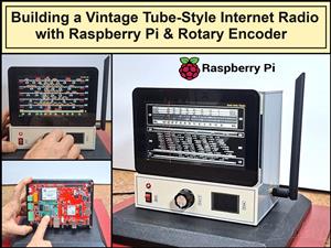 Building a Vintage Tube-Style Internet Radio with Raspberry Pi & Rotary Encoder
Internet radio (also known as web radio or net radio) is a digital audio service transmitted via th...
Building a Vintage Tube-Style Internet Radio with Raspberry Pi & Rotary Encoder
Internet radio (also known as web radio or net radio) is a digital audio service transmitted via th...
-
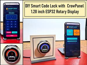 DIY Smart Code Lock with CrowPanel 1.28 ESP32 Rotary Display
A code lock is a keyless security device—either mechanical or electronic—that restricts access to d...
DIY Smart Code Lock with CrowPanel 1.28 ESP32 Rotary Display
A code lock is a keyless security device—either mechanical or electronic—that restricts access to d...
-
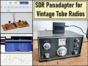 SDR Panadapter for Vintage Tube Radios – Step-by-Step Tutorial
A radio panadapter (or panoramic adapter) is a device or software tool used in amateur radio and ot...
SDR Panadapter for Vintage Tube Radios – Step-by-Step Tutorial
A radio panadapter (or panoramic adapter) is a device or software tool used in amateur radio and ot...
-
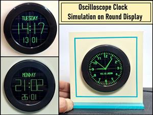 Oscilloscope Clock Simulation on a Round ESP32 Display
An oscilloscope clock is a circuit that turns an old analog oscilloscope into a stylish, retro-them...
Oscilloscope Clock Simulation on a Round ESP32 Display
An oscilloscope clock is a circuit that turns an old analog oscilloscope into a stylish, retro-them...
-
Programmable Mist Maker - XIAO / QT PY Extension
404 0 0 -
RadioHAT - Raspberry Pi radio development platform
316 0 1 -
-
-
-
-
ARPS-2 – Arduino-Compatible Robot Project Shield for Arduino UNO
2867 0 6 -
A Compact Charging Breakout Board For Waveshare ESP32-C3
3370 3 8 -
AI-driven LoRa & LLM-enabled Kiosk & Food Delivery System
3689 2 2


