


|
|
5LO38I CRT Tube 5 |
x 1 | |
|
|
12V to 300 V boost converter module |
x 1 | |
|
|
Linear Regulator with Adjustable Output |
x 1 | |
|
|
Resistors and capacitors |
x 1 | |
|
|
Small neon lamp |
x 1 |

|
Soldering Iron Kit |
DIY simplest small CRT Oscilloscope
An oscilloscope is a measuring instrument used to visualize and analyze electronic signals. It is commonly used in various fields, including electronics, telecommunications, engineering, and physics. Overall, oscilloscopes are essential tools for engineers, technicians, and scientists involved in electronics and signal analysis, enabling them to visualize, measure, and diagnose electrical waveforms accurately.

Nowadays, analog (CRT) oscilloscopes are no longer produced, but only digital ones, due to their huge advantages. One of the advantages of analog oscilloscopes is real-time, high-resolution imaging of the signal, and also easier to use than digital oscilloscopes.
In this video I will present to you the simplest possible way to make a retro-style analog oscilloscope with a cathode ray tube (CRT).
A cathode-ray tube (CRT) is a vacuum tube containing one or more electron guns, which emit electron beams that are manipulated to display images on a phosphorescent screen. A CRT tube can be obtained on the Internet for a relatively low price, and depending on the dimensions, it ranges from $20 and up.

And at the beginning, let me say that this is not a serious instrument, but only a demonstration model to describe the way these instruments work.
In previous years, this device has been described in several magazines and portals, but I could not find any pictures or a video presentation of its operation anywhere. So I decided to make it and present the results to you. As the title suggests, the device is extremely simple and consists of several components:
- The main part is the cathode ray tube, and in my case it is a miniature CRT marked 5LO38I with a diameter of only 5cm.
- An electronic part that is extremely simple, and consists only of a few resistors and capacitors.

- LM317 adjustable voltage regulator and two resistors to get the 6.3V needed for the tube heater.
- and power supply - this part is the most common reason why we do not start making devices with electronic tubes. Namely, for their normal operation, high voltages are needed, usually more than 200V, and such power supplies with a classic transformer are bulky and expensive. Specifically for this purpose I used this small compact boost converter which costs only 3 dollars and with 12V at the input gives an output of 45 to 400 Volts, which can be changed continuously with a small potentiometer. The power is quite sufficient for any CRT tube..

And now let's explane how this small oscilloscope works.
The input signal is fed to the Y input via a suitable capacitor to one of the Y deflection plates. For X deflection we use a neon lamp oscillator to generate a timebase, and with a focus regulator circuit we have a complete oscilloscope. Operation of the horizontal deflection oscillator is visible as the gentle flickering of the neon lamp. Whenever the voltage across the parallel-connected capacitor reaches the strike voltage of the lamp, it is discharged with a brief pulse of current. It is hard to imagine a simpler way to generate a sawtooth waveform.
Now, if a signal is applied to the Y input, we should be able to see the waveform on the screen. So, I have shown how little circuitry is required to make a real working oscilloscope.

Let me mention that this device is double isolated from the city voltage network. Once in the external power supply, and the second time in the boost converter.
At first start, it takes a certain amount of time for the cathode to start emitting electrons and an image appears on the screen. Now we will feed the sinusoidal signal generated by this tone generator to the input.

The shape of this signal appears on the screen. We can see that we get a stable image only at certain frequency values because, for the sake of simplicity, the device does not contain a trigger circuit. ( We can also look at the shape of the square wave generated by this small generator. ) If we increase the amplitude of the input sinusoidal signal, the peaks of the sinusoid will be cut off, and thus a trapezoidal signal is obtained.

The device is installed in a suitable box made of PVC board with a thickness of 3 and 5 mm and covered with self-adhesive wallpaper.
Otherwise my intention is to make a simple horizontal and vertical signal amplifier in the future and adapt this small CRT screen for a simple Arduino Oscilloscope clock. Hopefully an oscilloscope clock project will follow soon in one of my next videos.


DIY simplest small CRT Oscilloscope


Raspberry Pi 5 7 Inch Touch Screen IPS 1024x600 HD LCD HDMI-compatible Display for RPI 4B 3B+ OPI 5 AIDA64 PC Secondary Screen(Without Speaker)
BUY NOW


- Comments(0)
- Likes(7)
More by Mirko Pavleski
-
 Arduino 3D Printed self Balancing Cube
Self-balancing devices are electronic devices that use sensors and motors to keep themselves balanc...
Arduino 3D Printed self Balancing Cube
Self-balancing devices are electronic devices that use sensors and motors to keep themselves balanc...
-
 DIY Avionics Simulator with ESP32 - Artificial Horizon, Compass & Altimeter
The inspiration for this project comes from classical aircraft cockpit instruments used for navigat...
DIY Avionics Simulator with ESP32 - Artificial Horizon, Compass & Altimeter
The inspiration for this project comes from classical aircraft cockpit instruments used for navigat...
-
 DIY Miniature X-Ray Machine using a TV Vacuum Tube DY86
An X-ray machine (or radiograph) is a quick, painless medical test that produces images of the struc...
DIY Miniature X-Ray Machine using a TV Vacuum Tube DY86
An X-ray machine (or radiograph) is a quick, painless medical test that produces images of the struc...
-
 Simple SDR Receiver Using 2x NE612 - Dual Conversion, Superheterodyne (0.1–30 MHz)
SDR (Software Defined Radio) is a radio system in which most of the functions of a classic radio (f...
Simple SDR Receiver Using 2x NE612 - Dual Conversion, Superheterodyne (0.1–30 MHz)
SDR (Software Defined Radio) is a radio system in which most of the functions of a classic radio (f...
-
 DIY Vintage TV VU Meter with peak indicators
Some time ago in one of my projects I presented you a way to turn a black and white old mini TV int...
DIY Vintage TV VU Meter with peak indicators
Some time ago in one of my projects I presented you a way to turn a black and white old mini TV int...
-
 DIY Tesla Coil based Plasma Rife Machine
In several of my previous videos, I presented you with different ways to make a Rife Machine, from ...
DIY Tesla Coil based Plasma Rife Machine
In several of my previous videos, I presented you with different ways to make a Rife Machine, from ...
-
 ESP32 Analog VU Meter – Smooth Needle, Real Audio Response (DIY Build)
In several of my previous videos I have shown you how to make analog VU meters emulated on differen...
ESP32 Analog VU Meter – Smooth Needle, Real Audio Response (DIY Build)
In several of my previous videos I have shown you how to make analog VU meters emulated on differen...
-
 The Ultimate Smartphone VFO ESP32 & Si5351 Wireless Control
Variable frequency oscillators (VFOs) are commonly used in radio transmitters and receivers, especi...
The Ultimate Smartphone VFO ESP32 & Si5351 Wireless Control
Variable frequency oscillators (VFOs) are commonly used in radio transmitters and receivers, especi...
-
 DIY Shortwave Propagation Monitor - Measure Ionosphere Conditions
Shortwave Propagation is the way radio waves in the 3 to 30 MHz range travel from point A to point ...
DIY Shortwave Propagation Monitor - Measure Ionosphere Conditions
Shortwave Propagation is the way radio waves in the 3 to 30 MHz range travel from point A to point ...
-
 Professional grade Smart Lock with ESP32, BLE and Android App Control
An electronic codelock is a security device that grants access using a numerical sequence—a PIN cod...
Professional grade Smart Lock with ESP32, BLE and Android App Control
An electronic codelock is a security device that grants access using a numerical sequence—a PIN cod...
-
 Building a 3-Input Stereo ECC83 (12AX7) Tube Preamp
Some time ago I presented you a project for a 3W stereo tube amplifier with a GU32 output vacuum t...
Building a 3-Input Stereo ECC83 (12AX7) Tube Preamp
Some time ago I presented you a project for a 3W stereo tube amplifier with a GU32 output vacuum t...
-
 ESP32 Weather Dashboard with Satellite Maps and 16-day Weather Forecast
As you can see from my previous videos, besides Electronics, my fields of experimentation and proje...
ESP32 Weather Dashboard with Satellite Maps and 16-day Weather Forecast
As you can see from my previous videos, besides Electronics, my fields of experimentation and proje...
-
 Retro Analog VU Meter on Round dispalys (ESP32 and GC9A01)
Recently, in one of my previous videos I presented you a Retro VU Meter project on round displays ...
Retro Analog VU Meter on Round dispalys (ESP32 and GC9A01)
Recently, in one of my previous videos I presented you a Retro VU Meter project on round displays ...
-
 Ultimate 2-Player Reaction Timer with WS2812B LED Strips & Arduino
Arcade reaction game is a genre of play designed to test a player's physical response time and hand...
Ultimate 2-Player Reaction Timer with WS2812B LED Strips & Arduino
Arcade reaction game is a genre of play designed to test a player's physical response time and hand...
-
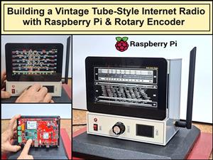 Building a Vintage Tube-Style Internet Radio with Raspberry Pi & Rotary Encoder
Internet radio (also known as web radio or net radio) is a digital audio service transmitted via th...
Building a Vintage Tube-Style Internet Radio with Raspberry Pi & Rotary Encoder
Internet radio (also known as web radio or net radio) is a digital audio service transmitted via th...
-
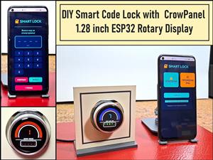 DIY Smart Code Lock with CrowPanel 1.28 ESP32 Rotary Display
A code lock is a keyless security device—either mechanical or electronic—that restricts access to d...
DIY Smart Code Lock with CrowPanel 1.28 ESP32 Rotary Display
A code lock is a keyless security device—either mechanical or electronic—that restricts access to d...
-
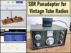 SDR Panadapter for Vintage Tube Radios – Step-by-Step Tutorial
A radio panadapter (or panoramic adapter) is a device or software tool used in amateur radio and ot...
SDR Panadapter for Vintage Tube Radios – Step-by-Step Tutorial
A radio panadapter (or panoramic adapter) is a device or software tool used in amateur radio and ot...
-
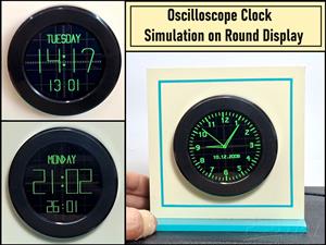 Oscilloscope Clock Simulation on a Round ESP32 Display
An oscilloscope clock is a circuit that turns an old analog oscilloscope into a stylish, retro-them...
Oscilloscope Clock Simulation on a Round ESP32 Display
An oscilloscope clock is a circuit that turns an old analog oscilloscope into a stylish, retro-them...
-
Programmable Mist Maker - XIAO / QT PY Extension
433 0 0 -
RadioHAT - Raspberry Pi radio development platform
339 0 1 -
-
-
-
-
ARPS-2 – Arduino-Compatible Robot Project Shield for Arduino UNO
2887 0 6 -
A Compact Charging Breakout Board For Waveshare ESP32-C3
3386 3 8 -
AI-driven LoRa & LLM-enabled Kiosk & Food Delivery System
3717 2 2


