


|
|
Neodimium magnet |
x 1 | |
|
|
Small E-type trafo |
x 1 | |
|
|
Aluminum plate with a thickness of about 1 mm |
x 1 | |
|
|
spring |
x 1 |

|
Soldering Iron Kit |
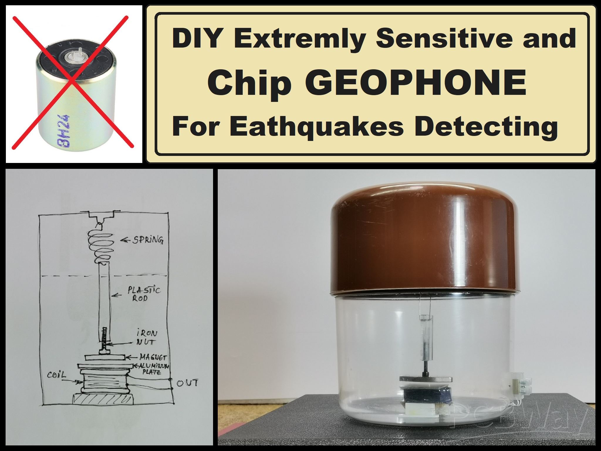
DIY Extremly Sensitive and cheap Geophone sensor for Earthquakes detecting
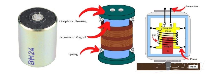
A geophone is a device used in geophysics to detect ground movement. It is specifically designed to measure seismic waves, which are produced by various sources, including earthquakes, and explosions. Typically consist of a mass suspended on a spring and a coil of wire within a magnetic field. When the ground shakes due to seismic activity, the mass moves, causing the coil to move within the magnetic field. This movement induces an electrical voltage in the coil.
This signal is then amplified and filtered, then it is brought to a computer where it is visualized and logged for later analysis with specially designed software for this purpose. Unfortunately, these sensors are mostly unavailable to self-builders due to their high price. This time I will describe to you how to make such a sensor yourself for free from parts that can be found in any workshop.
However, the sensitivity does not lag behind commercial geophones at all. Even this sensor reacts to shocks in all possible directions which makes it incredibly practical, In other words, it replaces many different types of Geophones.
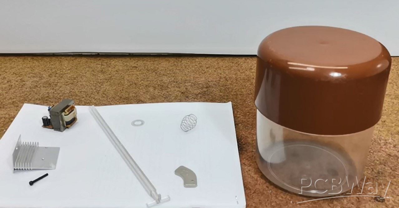
We only need a few components to make it.
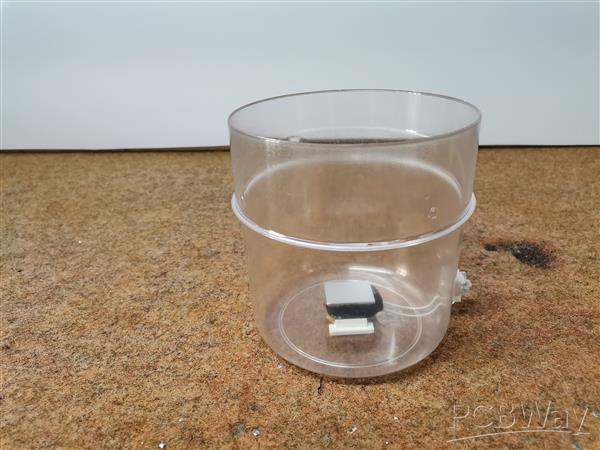
- A plastic container, which serves to isolate the sensor from external influences, and it is preferable to be transparent (I use an ordinary plastic box for storing sugar or coffee)
- A small mains transformer taken out of an old electronic device with a power of a few watts
- Neodymium magnet (I use a magnet removed from an old PC hard drive)
- Aluminum or copper plate with a thickness of about 1 mm
- light spring
- and some nuts and bolts as needed
This project is sponsored by PCBWay. They has all the services you need to create your project at the best price, whether is a scool project, or complex professional project. On PCBWay you can share your experiences, or get inspiration for your next project. They also provide completed Surface mount SMT PCB assemblY service at a best price, and ISO9001 quality control. Visit pcbway.com for more services.

This time we will make only the Geophone, and in one of the following videos I will present you the method of making the signal amplifier, filter, as well as the A/D converter, where I will try to do it in the simplest way so that it is closer to a larger number of enthusiasts who potentially would like to make it. I will also describe how to set up a simple 24/7 monitoring software to work with this sensor.
Now let's start making the sensor. First we need to disassemble the transformer, actually separate the windings from the metal part.

We need the primary winding, which contains a larger number of windings with a thinner wire. If the windings are covered with insulating tape, then with an ohmmeter we look for the winding with the highest resistance. Of course, we can also make this coil by winding 500 to 1500 turns of thin lacquered copper wire with a diameter of 0.1 mm

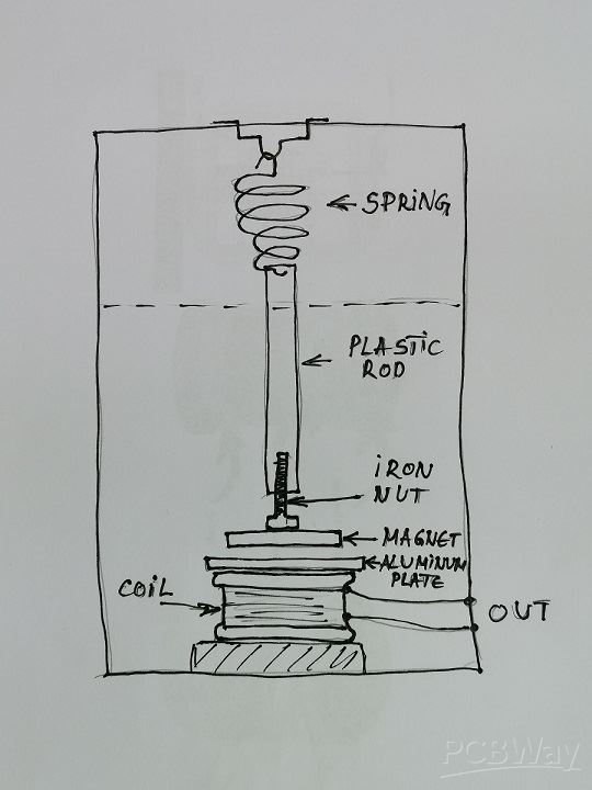
This winding need to be glued to the bottom of the box. Then we take the two leads from the winding with thin wires outside the box to a small terminal. Next, we glue the aluminum plate on top of the coil, which should have the same shape as the coil. This plate has the function of preventing the long-term oscillation of the magnet after the earthquake, and this process is called damping. When a magnetic field moves through a conductor the movement induces an eddy current in the conductor. The flow of electrons in the conductor immediately creates an opposing magnetic field which results in damping of the magnet.
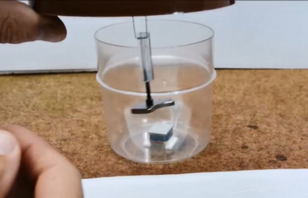
The length of the combination spring + rod + screw + magnet should be adjusted so that when the lid is closed, the magnet hangs approximately 1-1.5 mm above the aluminum plate.

As you can see, the sensor is sensitive to shocks from all directions and axes. During a vertical shock, which usually occurs near the epicenter, the spring reacts, and during a horizontal movement, the pendulum can move in all directions 360 degrees. Such sensors that respond in all axes are very expensive and are used only for professional purposes. This diy geophone can be mounted on the ground using spikes or other mechanisms to ensure good contact with the Earth's surface. In some cases, geophones are buried at varying depths.

And finally a short conclusion: This sensor is conceived as part of the final project, which will actually be a stand-alone seismometer and will display the relative intensity of the earthquake at the point of detection. Determining the direction, distance, and magnitude of an earthquake at the epicenter requires the interaction of at least three seismometers, but for this topic in another project. In the next video that I will promote soon, will be described the electronic part consisting of an amplifier, filter, A/D converter and PC software. Thus we will get a complete extremely cheap and sensitive home seismometer whose results (seismograms) are almost identical to those of the official seismological institutes. In the following, I will present to you several reports from my seismometer, which uses the above-described sensor.
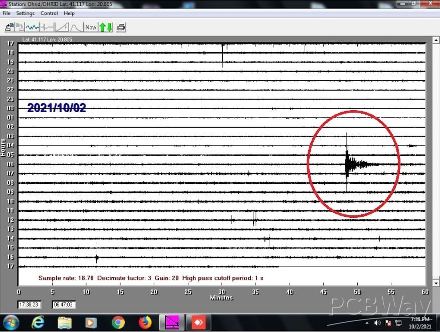
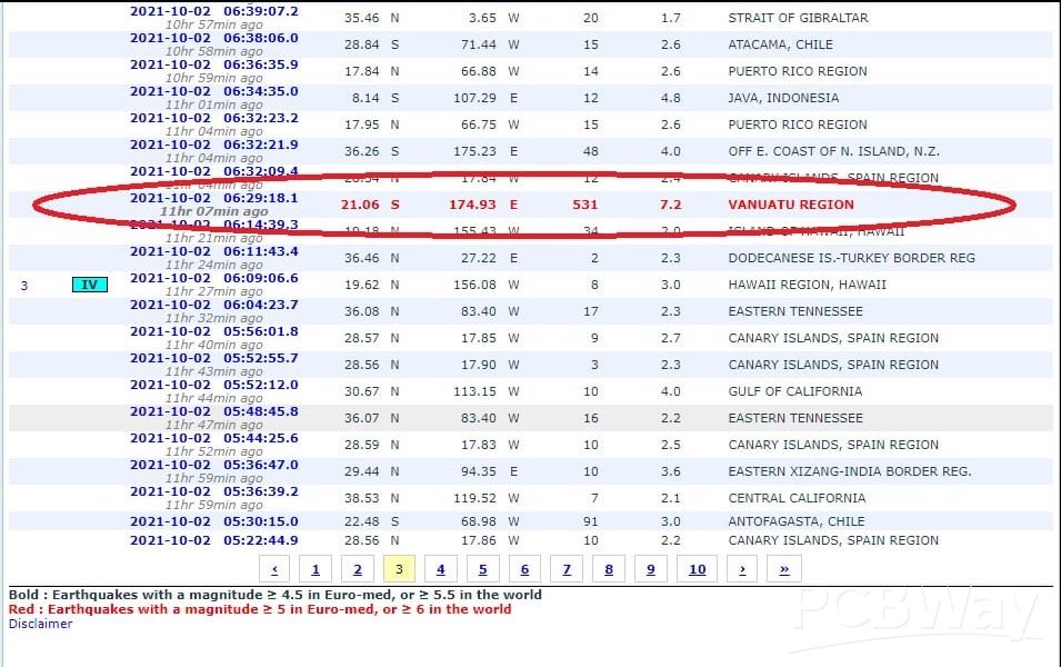
1. An earthquake with a magnitude of 7.2 on the Richter scale occurred 2 October 2021 at 08:29 h Ohrid time at a depth of 530 km on the island of Vanuatu, west of Australia in the Pacific Ocean. This is how this earth looks like, taken by my Seismometer at a distance of 15600 km from Ohrid

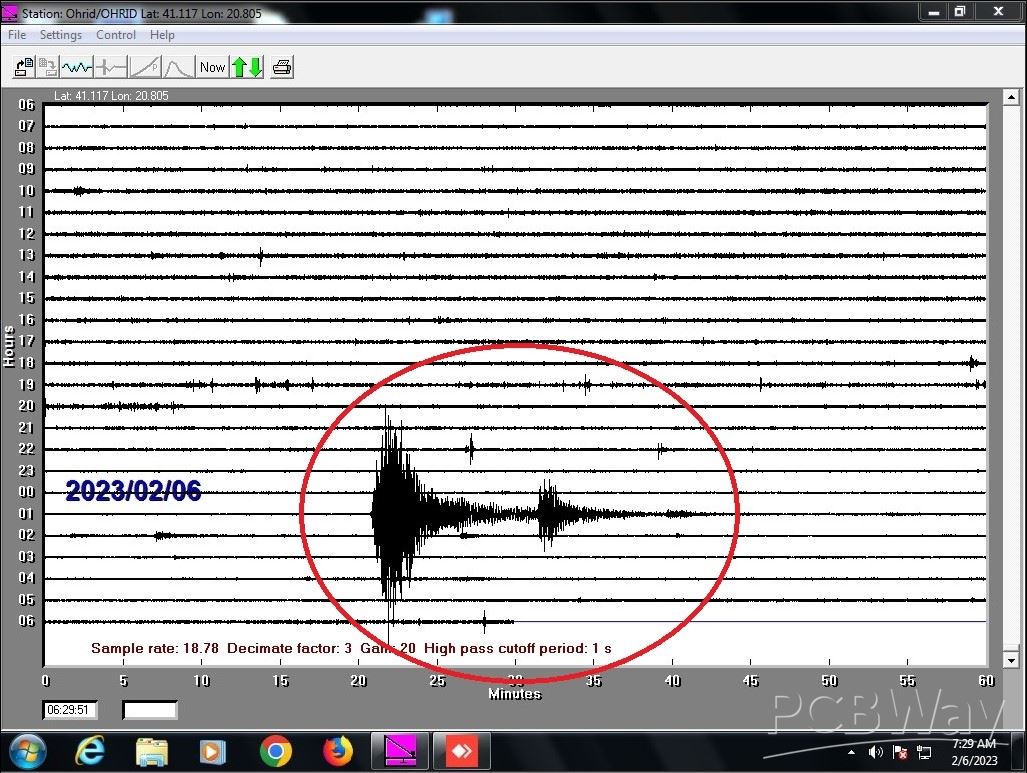
2. A very strong earthquake occurred at 01:17 UTC (6 February 2023), with a magnitude of 7.8 degrees on the Richter scale 37 km WNW of Gaziantep, Turkey
3.Local Earthquake with a magnitude of 3.8 on the Richter scale northeast of Korca, Albania 25 April 2023


DIY Extremly Sensitive and cheap Geophone sensor for Earthquakes detecting


Raspberry Pi 5 7 Inch Touch Screen IPS 1024x600 HD LCD HDMI-compatible Display for RPI 4B 3B+ OPI 5 AIDA64 PC Secondary Screen(Without Speaker)
BUY NOW


- Comments(0)
- Likes(0)
More by Mirko Pavleski
-
 Arduino 3D Printed self Balancing Cube
Self-balancing devices are electronic devices that use sensors and motors to keep themselves balanc...
Arduino 3D Printed self Balancing Cube
Self-balancing devices are electronic devices that use sensors and motors to keep themselves balanc...
-
 The Ultimate Smartphone VFO ESP32 & Si5351 Wireless Control
Variable frequency oscillators (VFOs) are commonly used in radio transmitters and receivers, especi...
The Ultimate Smartphone VFO ESP32 & Si5351 Wireless Control
Variable frequency oscillators (VFOs) are commonly used in radio transmitters and receivers, especi...
-
 DIY Shortwave Propagation Monitor - Measure Ionosphere Conditions
Shortwave Propagation is the way radio waves in the 3 to 30 MHz range travel from point A to point ...
DIY Shortwave Propagation Monitor - Measure Ionosphere Conditions
Shortwave Propagation is the way radio waves in the 3 to 30 MHz range travel from point A to point ...
-
 Professional grade Smart Lock with ESP32, BLE and Android App Control
An electronic codelock is a security device that grants access using a numerical sequence—a PIN cod...
Professional grade Smart Lock with ESP32, BLE and Android App Control
An electronic codelock is a security device that grants access using a numerical sequence—a PIN cod...
-
 Building a 3-Input Stereo ECC83 (12AX7) Tube Preamp
Some time ago I presented you a project for a 3W stereo tube amplifier with a GU32 output vacuum t...
Building a 3-Input Stereo ECC83 (12AX7) Tube Preamp
Some time ago I presented you a project for a 3W stereo tube amplifier with a GU32 output vacuum t...
-
 ESP32 Weather Dashboard with Satellite Maps and 16-day Weather Forecast
As you can see from my previous videos, besides Electronics, my fields of experimentation and proje...
ESP32 Weather Dashboard with Satellite Maps and 16-day Weather Forecast
As you can see from my previous videos, besides Electronics, my fields of experimentation and proje...
-
 Retro Analog VU Meter on Round dispalys (ESP32 and GC9A01)
Recently, in one of my previous videos I presented you a Retro VU Meter project on round displays ...
Retro Analog VU Meter on Round dispalys (ESP32 and GC9A01)
Recently, in one of my previous videos I presented you a Retro VU Meter project on round displays ...
-
 Ultimate 2-Player Reaction Timer with WS2812B LED Strips & Arduino
Arcade reaction game is a genre of play designed to test a player's physical response time and hand...
Ultimate 2-Player Reaction Timer with WS2812B LED Strips & Arduino
Arcade reaction game is a genre of play designed to test a player's physical response time and hand...
-
 Building a Vintage Tube-Style Internet Radio with Raspberry Pi & Rotary Encoder
Internet radio (also known as web radio or net radio) is a digital audio service transmitted via th...
Building a Vintage Tube-Style Internet Radio with Raspberry Pi & Rotary Encoder
Internet radio (also known as web radio or net radio) is a digital audio service transmitted via th...
-
 DIY Smart Code Lock with CrowPanel 1.28 ESP32 Rotary Display
A code lock is a keyless security device—either mechanical or electronic—that restricts access to d...
DIY Smart Code Lock with CrowPanel 1.28 ESP32 Rotary Display
A code lock is a keyless security device—either mechanical or electronic—that restricts access to d...
-
 SDR Panadapter for Vintage Tube Radios – Step-by-Step Tutorial
A radio panadapter (or panoramic adapter) is a device or software tool used in amateur radio and ot...
SDR Panadapter for Vintage Tube Radios – Step-by-Step Tutorial
A radio panadapter (or panoramic adapter) is a device or software tool used in amateur radio and ot...
-
 Oscilloscope Clock Simulation on a Round ESP32 Display
An oscilloscope clock is a circuit that turns an old analog oscilloscope into a stylish, retro-them...
Oscilloscope Clock Simulation on a Round ESP32 Display
An oscilloscope clock is a circuit that turns an old analog oscilloscope into a stylish, retro-them...
-
 DIY Simple GU32 Tube Stereo Amplifier (2x3W on 12VDC)
Vacuum tube amplifiers are often favored for their smooth harmonic distortion, especially in the low...
DIY Simple GU32 Tube Stereo Amplifier (2x3W on 12VDC)
Vacuum tube amplifiers are often favored for their smooth harmonic distortion, especially in the low...
-
 DIY 3-Display OLED Clock with Arduino and I2C Multiplexer
In this video I want to present you another unusual clock to add to my large collection of such DIY...
DIY 3-Display OLED Clock with Arduino and I2C Multiplexer
In this video I want to present you another unusual clock to add to my large collection of such DIY...
-
 Build a 5-Day forecast Raspberry Pi Weather Dashboard (Step-by-Step)
Recently in one of my previous videos,I introduced you to the 7 inch Elecrow Pi Terminal and how to...
Build a 5-Day forecast Raspberry Pi Weather Dashboard (Step-by-Step)
Recently in one of my previous videos,I introduced you to the 7 inch Elecrow Pi Terminal and how to...
-
 ESP32 Aneroid Barometer using Squareline Studio and LVGL on CrowPanel Round display
A barometer is a scientific instrument used to measure atmospheric pressure. Rising Pressure genera...
ESP32 Aneroid Barometer using Squareline Studio and LVGL on CrowPanel Round display
A barometer is a scientific instrument used to measure atmospheric pressure. Rising Pressure genera...
-
 LINAMP Project – Winamp-Style Audio Front Panel on Raspberry Pi 5
Winamp is one of the most iconic and historically significant digital media players ever created. I...
LINAMP Project – Winamp-Style Audio Front Panel on Raspberry Pi 5
Winamp is one of the most iconic and historically significant digital media players ever created. I...
-
 Retro Style radio with CrowPanel 2.1inch round Display (TEA5767)
Some time ago I presented you a clock project with CrowPanel 2.1inch-HMI ESP32 Rotary Display 480*4...
Retro Style radio with CrowPanel 2.1inch round Display (TEA5767)
Some time ago I presented you a clock project with CrowPanel 2.1inch-HMI ESP32 Rotary Display 480*4...
-
-
ARPS-2 – Arduino-Compatible Robot Project Shield for Arduino UNO
2213 0 5 -
A Compact Charging Breakout Board For Waveshare ESP32-C3
2714 3 7 -
AI-driven LoRa & LLM-enabled Kiosk & Food Delivery System
2908 2 0 -
-
-
-
ESP32-C3 BLE Keyboard - Battery Powered with USB-C Charging
2936 0 2 -


