


|
Soldering Iron Kit |
|

|
arduino IDEArduino
|
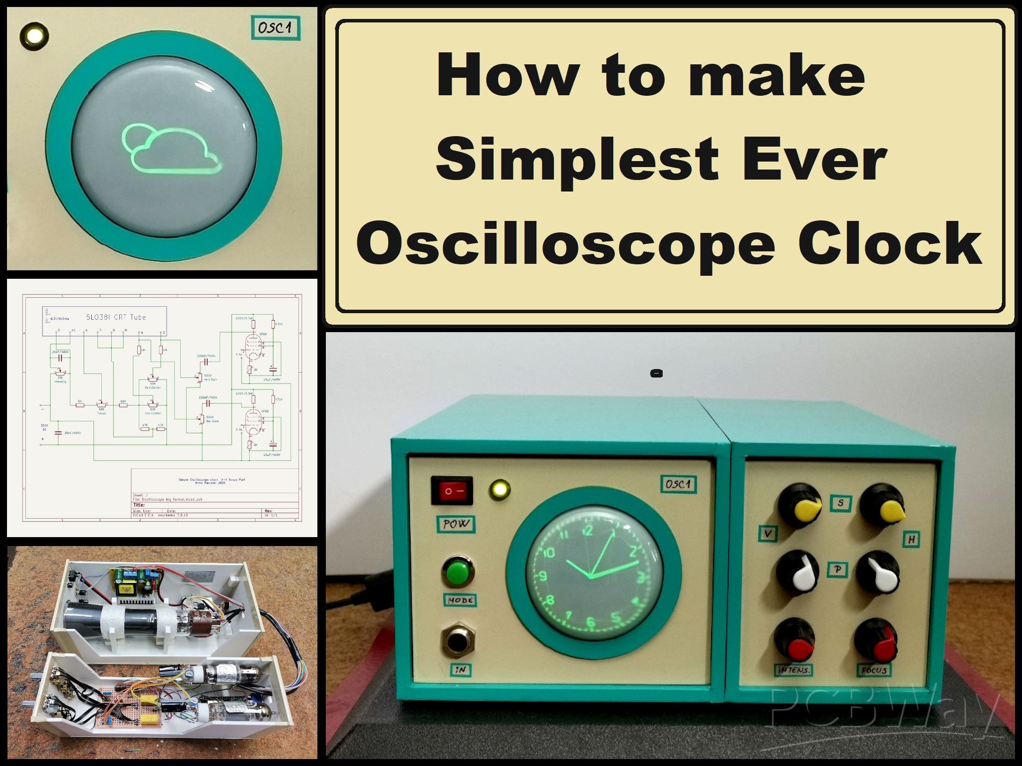
How to make Simplest ever Oscilloscope Clock
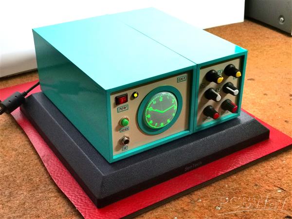
An oscilloscope clock is a unique and creative way to display the time using an oscilloscope, which is a test and measurement instrument typically used to visualize and analyze electronic signals. In one of my previous videos I presented you a way to make the simplest oscilloscope with a small 2 inch CRT tube. This time I will describe to you also a very simple way how to make a Oscilloscope Clock with the same CRT tube. There are several projects of this type on the Internet, but they are relatively complex for self-construction, so I decided to make an Oscilloscope clock in the simplest possible way. It even avoids the use of a mains transformer which is expensive and difficult to obtain, and initially the device works on 12V. But despite its simplicity, it is fully functional, highly adjustable, and has the option of automatically setting the time via the Internet. So it even outperforms more complex devices of this class.
Basically the device consists of two parts, and one is a signal generator usually made with the help of a microcontroller, and the other part is an X-Y mode oscilloscope that visualizes this signal in the form of an analog clock.
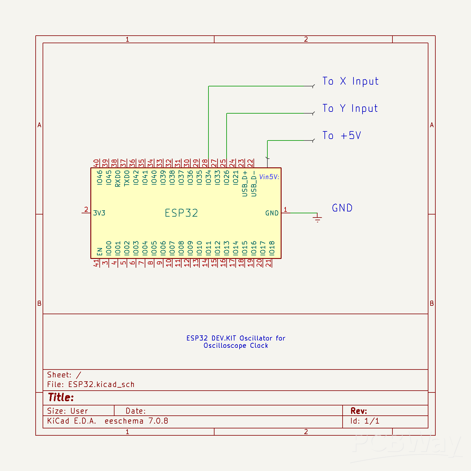
First I will focus on the signal generation part. It is extremely simple and uses only an ESP32 Microcontroller board without any external components.
The code is the work of Mauro Pintus , and I just made a small modification, so now with a button we can choose between a clock with standard or Roman numerals. If you enter the data of your local Wi-Fi network in the code, the time will be updated automatically via the Internet, and if you do not have the Internet, the initial time that will appear when the clock starts can also be adjusted in the code in the (given) lines:
int h=10; //Start Hour
int m=8; //Start Minutes
int s=37; //Start Seconds
This project is sponsored by PCBWay. Visit the PCBWay website and save big, with a time-limited promotion on purple solder mask. From September 1st to September 30th you can get 10 pcs of 2-layer 100x100mm PCBs in purple for only $5. PCBWay has all the services you need to create your project at the best price.

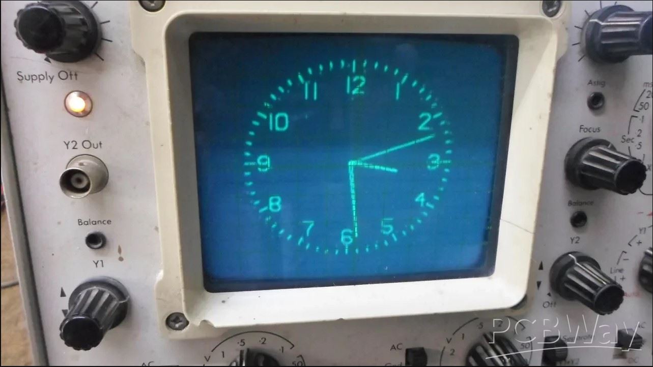
Otherwise, I successfully tested a version of the code where the time is set manually through three buttons, but for the sake of simplicity, I left this version out. This time I will not dwell on the installation of the code on ESP32 , as it is described in many detailed tutorials that you can find on the Internet. Regarding the connection method, pin 25 of ESP32 should be connected to X Input, and pin 26 to Y Input of oscilloscope. The ground from the microcontroller is connected to the ground from the scope. Also in one of my older videos you can see how this clock works on a commercial Oscilloscope.
Next, I will briefly describe the method of making the X-Y mode oscilloscope. As I mentioned before, the device has a complete control of the position and size of the image, which is done with the help of four potentiometers, and there are also potentiometers for adjusting the intensity of the light as well as for focusing the image.
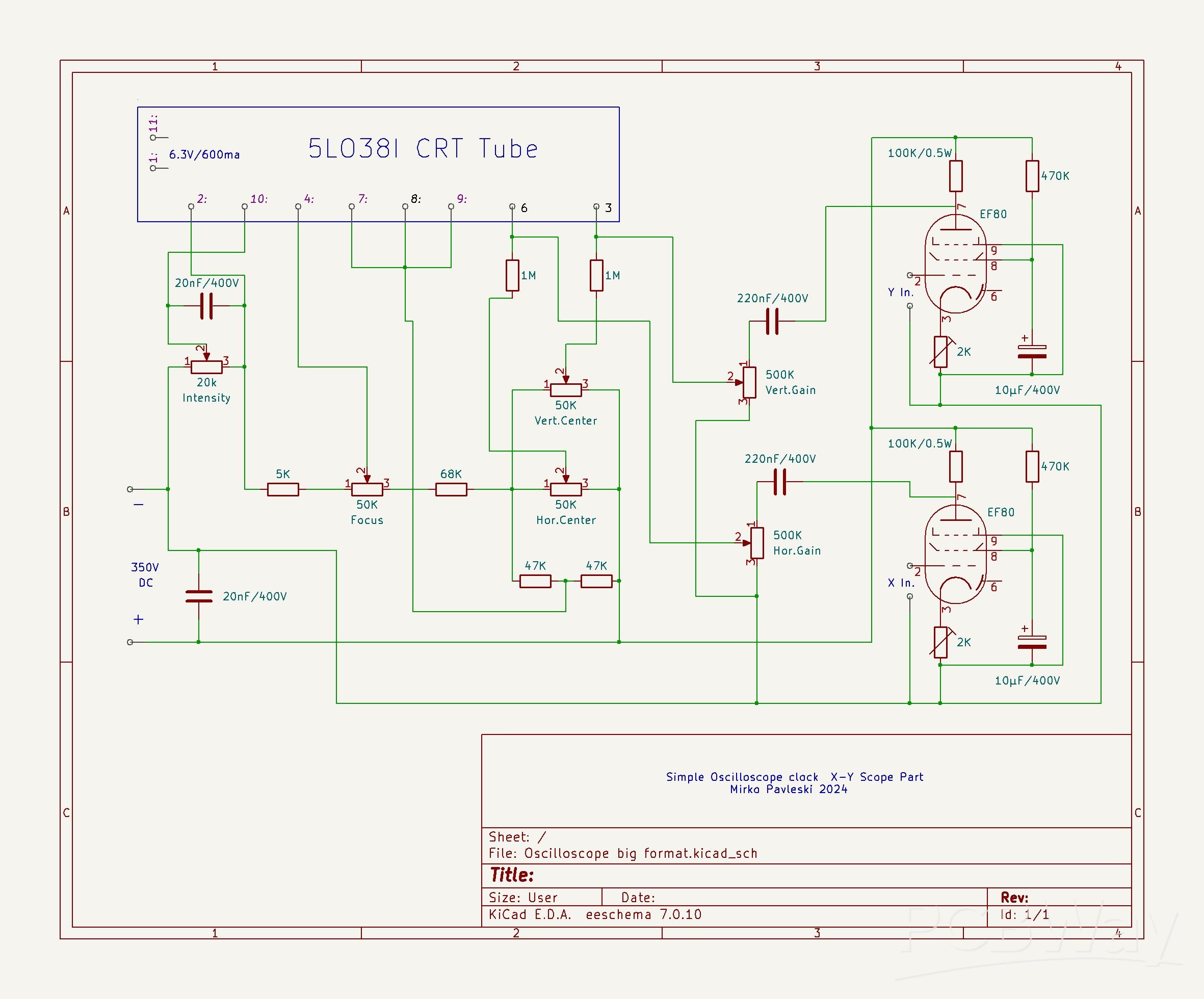
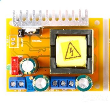
As in my previous oscilloscope project, I will also use an inexpensive DC-DC step-up for power supply, where with an input voltage of 12V, the output voltage can be continuously adjusted within the range of 45 to 390 volts.
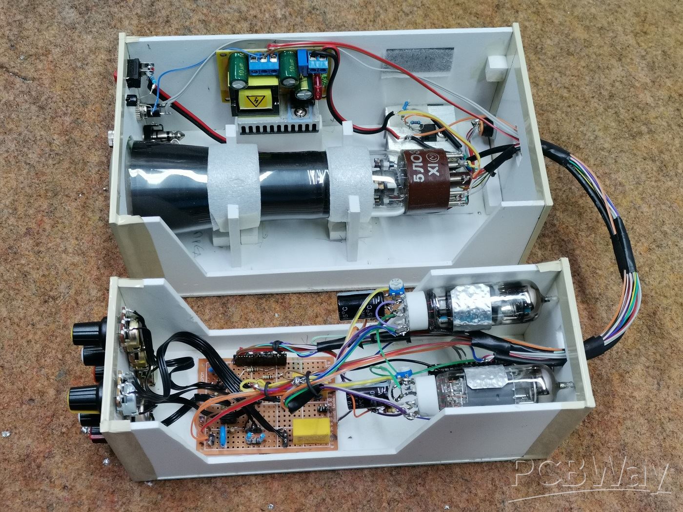
So the complete device consists of the following components:
- 2 Inch CRT display type 5LO38I
- Step Up Power supply module 12V to 300V
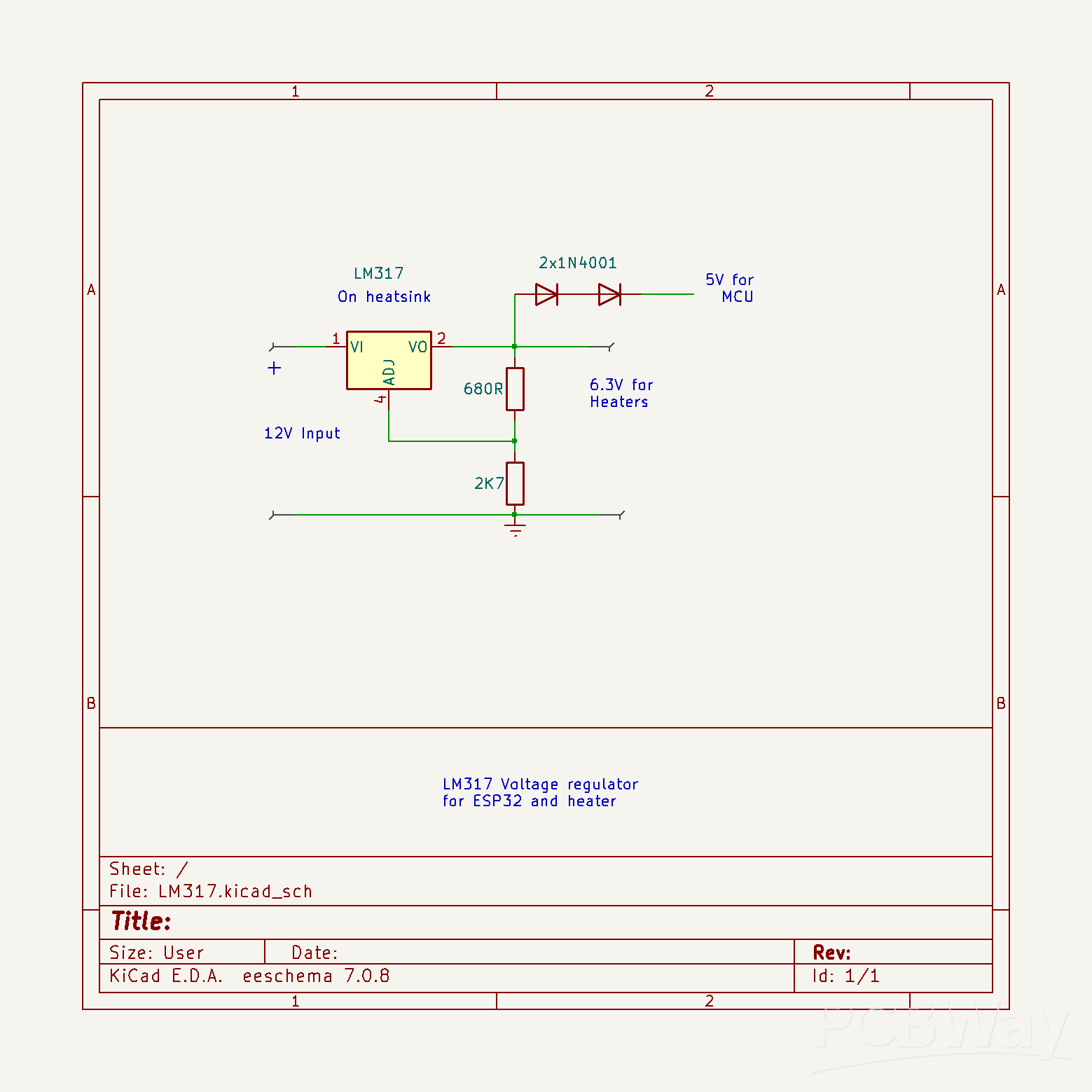
- LM317 voltage regulator with which we get a voltage of 6.3V for heating the tubes
- Two EF80 tubes as horisontal and vertical deflection amplifiers
- Six control potentiometers
- "Mode" button
- several passive elements, resistors and capacitors,
- and ESP32 microcontroller board
At the input of the boost converter we bring 12V, which then increases to 350V. The output voltage can be precisely adjusted with this multiturn potentiometer. This high voltage serves to power the CRT display and the tubes. An input of LM317 voltage regulator is connected to the 12V , the output of which produces 6.3 volts used for heating the three tubes. Since the heating current reaches a value greater than 1A, the regulator must be mounted on an aluminum heatsink. I got the necessary 5V for powering the ESP32 microcontroller by connecting two diodes in series to the 6.3V output, which gives exactly 5V due to the voltage drop of the two diodes.

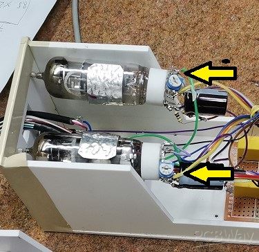
In fact, the basic idea of simplicity of the device required the use of a single power supply for all the components, and at the same time, it should be performed in a simple way. That's why this part of the project took me the most time.The two EF80 vacuum tubes are actually horizontal and vertical deflection amplifiers. Initially, I wanted to use MPSA45 NPN transistors for this purpose, but during a random mistake, they burned out and I didn't have any spares, so I decided to continue with vacuum tubes. But these tubes were used for a long time in old devices, so they had different characteristics, so instead of a fixed resistor, I placed trimmer potentiometers on the cathodes, with which I can adjust the clock circle as precisely as possible.
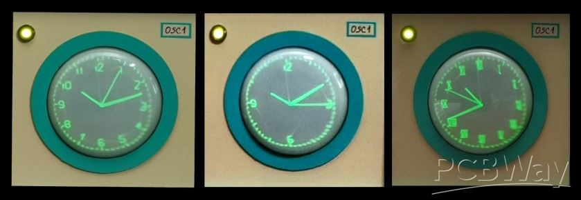
And now let's see how the device works in real conditions. After switching on, a certain time should pass for the cathodes of the tubes to heat up, and an image to appear on the CRT screen. During this time, the ESP32 updates the correct time if the Wi-Fi credentials are entered in the code, and so the clock starts working. Let's see how the picture adjustment potentiometers react.
I should mention that it takes a few to ten minutes for the image to finally stabilize on the screen. As I mentioned before, with the help of a button we can choose between a clock with standard and Roman numerals.
The screen should be shielded with a metal foil connected to grounding so that there is no influence of external electromagnetic fields on it. I haven't had a chance to try it, but I assume that the same circuit with minimal or no modifications should work with similar CRT tubes.
Very interesting is the option to draw various figures or text on the X-Y oscilloscope. If we bring signals with a certain frequency and shape to the inputs of the X-Y oscilloscope, we can get any figures, text or images on the screen.
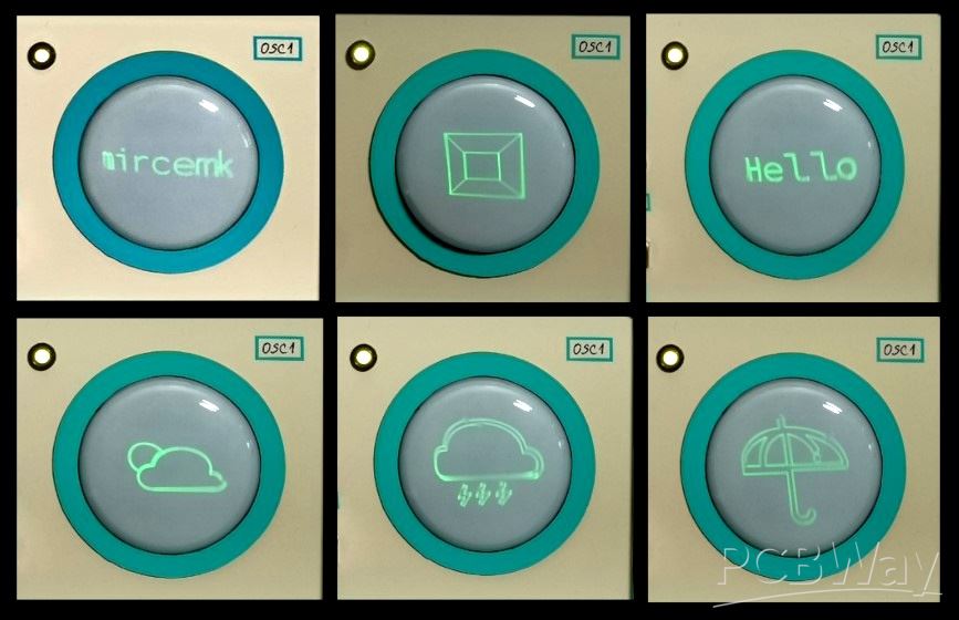
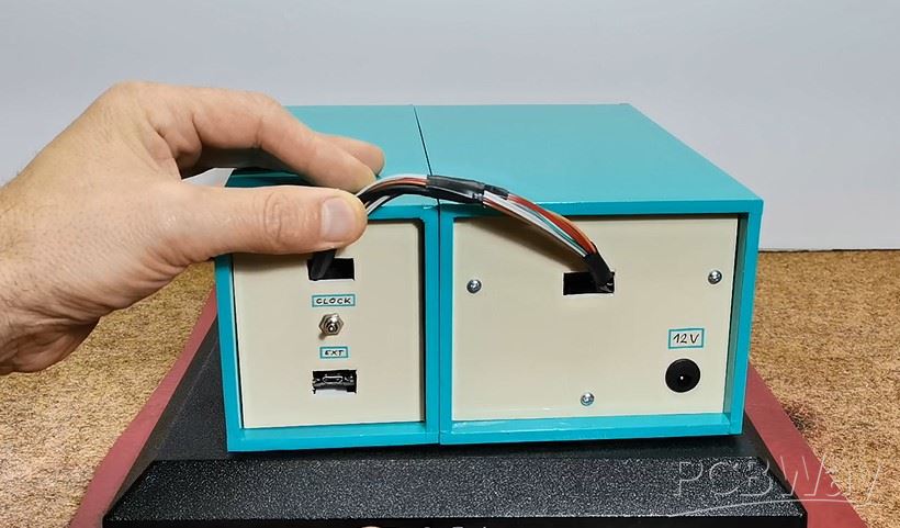
There are several PC Applications, which generate a signal on the sound card which is then converted into an image or text. For this purpose I have installed a switch on the back side through which we can choose the type of input signal between the MCU Clock, or an external signal source, in this case a PC sound card.
The device is installed in a suitable box made of PVC material with a thickness of 5 mm, and covered with colored self-adhesive wallpaper.
And finally a short conclusion:
Building an oscilloscope clock can be a very fun and educational electronics project. It combines aspects of programming, circuit design, and creativity. But we should keep in mind that this clock is almost unreadable in daylight, which is a characteristic of the CRT display itself, so those beautiful pictures of such devices that you see on the Internet are actually taken in a partially darkened environment. However, it is a great pleasure, especially for the younger generations of self-builders, to make such a retro clock, bearing in mind that for a relatively low price, remaining supplies of CRT screens and vacuum tubes can be obtained on internet.
SAFETY NOTE: Please do not attempt to recreate the experiments shown on this video unless you are familiar with High Voltage Safety Techniques! Direct Current even above 60V maybe lethal, even when the AC supply voltage has been disconnected due to the stored energy in the capacitors. I have no responsibility on any hazards caused by the circuit. Be very careful. This is a humble request.


How to make Simplest ever Oscilloscope Clock


Raspberry Pi 5 7 Inch Touch Screen IPS 1024x600 HD LCD HDMI-compatible Display for RPI 4B 3B+ OPI 5 AIDA64 PC Secondary Screen(Without Speaker)
BUY NOW


- Comments(1)
- Likes(0)
More by Mirko Pavleski
-
 Arduino 3D Printed self Balancing Cube
Self-balancing devices are electronic devices that use sensors and motors to keep themselves balanc...
Arduino 3D Printed self Balancing Cube
Self-balancing devices are electronic devices that use sensors and motors to keep themselves balanc...
-
 Elecrow All-in-One Arduino Starter Kit Review - 20 Projects & 16 Modules
This time I will describe a simple and practical way to enter the world of microcontrollers, specif...
Elecrow All-in-One Arduino Starter Kit Review - 20 Projects & 16 Modules
This time I will describe a simple and practical way to enter the world of microcontrollers, specif...
-
 ESP32-C3 Color Detector with TCS34725, Real-Time RGB Detection & Web Interface
Color detection is a fundamental task in many embedded systems – from industrial sorting machines t...
ESP32-C3 Color Detector with TCS34725, Real-Time RGB Detection & Web Interface
Color detection is a fundamental task in many embedded systems – from industrial sorting machines t...
-
 DIY ESP32 Telegram Flood Protection System - Smart Home Automation
Recently I had an unpleasant experience in my home, specifically my ground floor was flooded as a r...
DIY ESP32 Telegram Flood Protection System - Smart Home Automation
Recently I had an unpleasant experience in my home, specifically my ground floor was flooded as a r...
-
 Real-Time Air Traffic Radar using ESP32 + ADS-B Data
ADS-B, which stands for Automatic Dependent Surveillance-Broadcast, is the modern standard for trac...
Real-Time Air Traffic Radar using ESP32 + ADS-B Data
ADS-B, which stands for Automatic Dependent Surveillance-Broadcast, is the modern standard for trac...
-
 DIY Green Laser Night Sky Object Finder - Find Stars & Galaxies Instantly with great accuracy
As an amateur astronomer, especially at the beginning, the most difficult part of observing the nig...
DIY Green Laser Night Sky Object Finder - Find Stars & Galaxies Instantly with great accuracy
As an amateur astronomer, especially at the beginning, the most difficult part of observing the nig...
-
 DIY Avionics Simulator with ESP32 - Artificial Horizon, Compass & Altimeter
The inspiration for this project comes from classical aircraft cockpit instruments used for navigat...
DIY Avionics Simulator with ESP32 - Artificial Horizon, Compass & Altimeter
The inspiration for this project comes from classical aircraft cockpit instruments used for navigat...
-
 DIY Miniature X-Ray Machine using a TV Vacuum Tube DY86
An X-ray machine (or radiograph) is a quick, painless medical test that produces images of the struc...
DIY Miniature X-Ray Machine using a TV Vacuum Tube DY86
An X-ray machine (or radiograph) is a quick, painless medical test that produces images of the struc...
-
 Simple SDR Receiver Using 2x NE612 - Dual Conversion, Superheterodyne (0.1–30 MHz)
SDR (Software Defined Radio) is a radio system in which most of the functions of a classic radio (f...
Simple SDR Receiver Using 2x NE612 - Dual Conversion, Superheterodyne (0.1–30 MHz)
SDR (Software Defined Radio) is a radio system in which most of the functions of a classic radio (f...
-
 DIY Vintage TV VU Meter with peak indicators
Some time ago in one of my projects I presented you a way to turn a black and white old mini TV int...
DIY Vintage TV VU Meter with peak indicators
Some time ago in one of my projects I presented you a way to turn a black and white old mini TV int...
-
 DIY Tesla Coil based Plasma Rife Machine
In several of my previous videos, I presented you with different ways to make a Rife Machine, from ...
DIY Tesla Coil based Plasma Rife Machine
In several of my previous videos, I presented you with different ways to make a Rife Machine, from ...
-
 ESP32 Analog VU Meter – Smooth Needle, Real Audio Response (DIY Build)
In several of my previous videos I have shown you how to make analog VU meters emulated on differen...
ESP32 Analog VU Meter – Smooth Needle, Real Audio Response (DIY Build)
In several of my previous videos I have shown you how to make analog VU meters emulated on differen...
-
 The Ultimate Smartphone VFO ESP32 & Si5351 Wireless Control
Variable frequency oscillators (VFOs) are commonly used in radio transmitters and receivers, especi...
The Ultimate Smartphone VFO ESP32 & Si5351 Wireless Control
Variable frequency oscillators (VFOs) are commonly used in radio transmitters and receivers, especi...
-
 DIY Shortwave Propagation Monitor - Measure Ionosphere Conditions
Shortwave Propagation is the way radio waves in the 3 to 30 MHz range travel from point A to point ...
DIY Shortwave Propagation Monitor - Measure Ionosphere Conditions
Shortwave Propagation is the way radio waves in the 3 to 30 MHz range travel from point A to point ...
-
 Professional grade Smart Lock with ESP32, BLE and Android App Control
An electronic codelock is a security device that grants access using a numerical sequence—a PIN cod...
Professional grade Smart Lock with ESP32, BLE and Android App Control
An electronic codelock is a security device that grants access using a numerical sequence—a PIN cod...
-
 Building a 3-Input Stereo ECC83 (12AX7) Tube Preamp
Some time ago I presented you a project for a 3W stereo tube amplifier with a GU32 output vacuum t...
Building a 3-Input Stereo ECC83 (12AX7) Tube Preamp
Some time ago I presented you a project for a 3W stereo tube amplifier with a GU32 output vacuum t...
-
 ESP32 Weather Dashboard with Satellite Maps and 16-day Weather Forecast
As you can see from my previous videos, besides Electronics, my fields of experimentation and proje...
ESP32 Weather Dashboard with Satellite Maps and 16-day Weather Forecast
As you can see from my previous videos, besides Electronics, my fields of experimentation and proje...
-
 Retro Analog VU Meter on Round dispalys (ESP32 and GC9A01)
Recently, in one of my previous videos I presented you a Retro VU Meter project on round displays ...
Retro Analog VU Meter on Round dispalys (ESP32 and GC9A01)
Recently, in one of my previous videos I presented you a Retro VU Meter project on round displays ...
-
Programmable Mist Maker - XIAO / QT PY Extension
1054 2 1 -
RadioHAT - Raspberry Pi radio development platform
850 0 2 -
-
-
-
-
ARPS-2 – Arduino-Compatible Robot Project Shield for Arduino UNO
3316 0 6 -
A Compact Charging Breakout Board For Waveshare ESP32-C3
3921 3 8 -
AI-driven LoRa & LLM-enabled Kiosk & Food Delivery System
4309 2 2


