


|
Soldering Iron Kit |
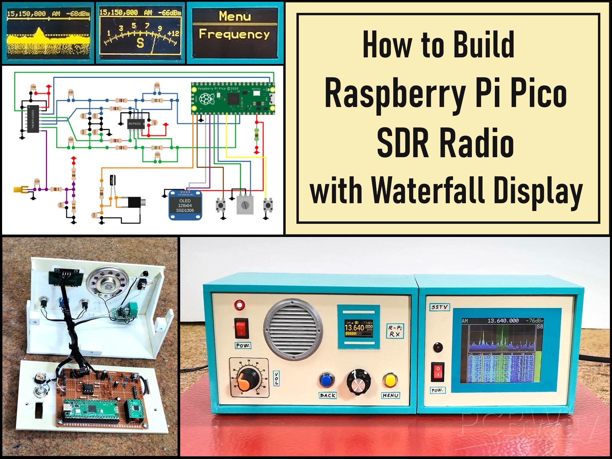
Build a Raspberry Pi Pico SDR Radio with Waterfall Display
Software-defined radio (SDR) is a radio communication system where components that have traditionally been implemented in analog hardware (such as mixers, filters, amplifiers, modulators, and demodulators) are instead implemented by means of software on a computer or embedded system. The biggest advantage of SDR is its flexibility. Because the functions are handled by software, you can change the radio's behavior by simply updating the software.
This time I will present you a wonderful example of how to make such a receiver using Raspberry Pi Pico.
Even this receiver works completely independently without the use of a PC and all functions are controlled directly on it and displayed on a small OLED display. The original project is presented on the 101 things website and the author is Jon Dawson , so all credits go to him. Also there are many more exelent Raspberry Pi Pico projects on this site and I hope to test and promote some of them in the near future.
This project is sponsored by PCBWay. Visit the PCBWay website and save big, with a time-limited promotion on purple solder mask. From September 1st to September 30th you can get 10 pcs of 2-layer 100x100mm PCBs in purple for only $5. PCBWay has all the services you need to create your project at the best price.

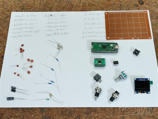
The receiver consists of a minimal number of components, but its huge number of functions and possibilities for various settings can rival even expensive commercial devices of this kind.
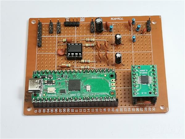
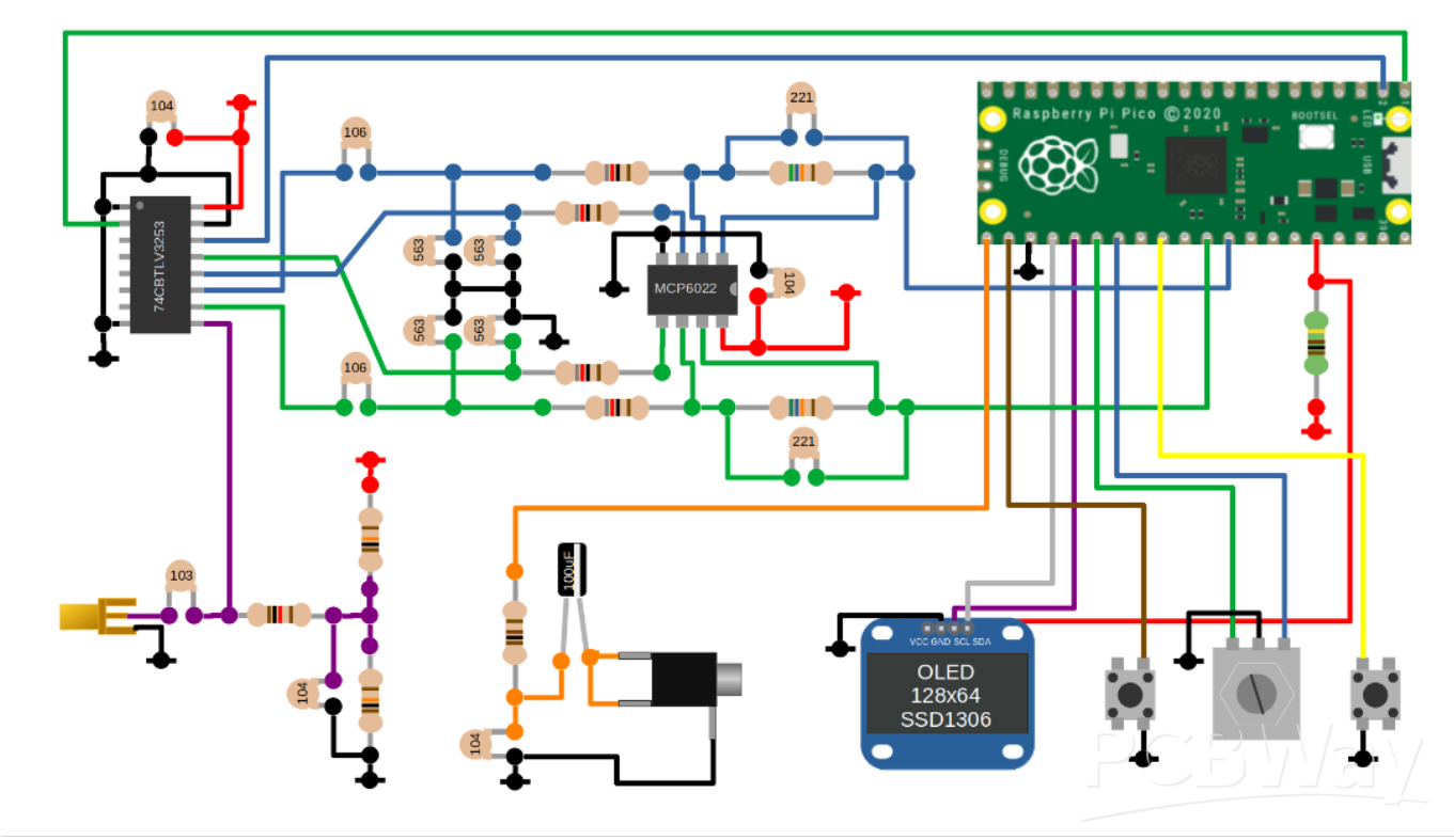
I made complete device on a universal PCB, and as you can see, the layout of the components is almost identical to the breadboard version of the schematic presented on the source page. I made the complete project on PCB in less than a day and was positively surprised by the fact that the device worked immediately upon first powering on.
The basic components are clearly visible and they are:
- Raspberry Pi Pico module
- CBTLV3253 Multiplexer IC
- TL082 Dual Operational Amplifier IC (I use it instead of MCP 6022, and NE5532 can also be used)
- SSD1306 OLED Display
- and rotary Encoder and two buttons
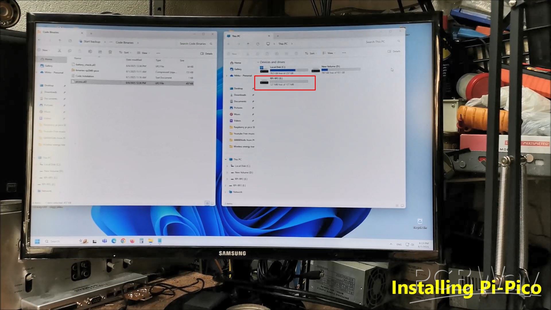
With this, the installation of the code is complete.
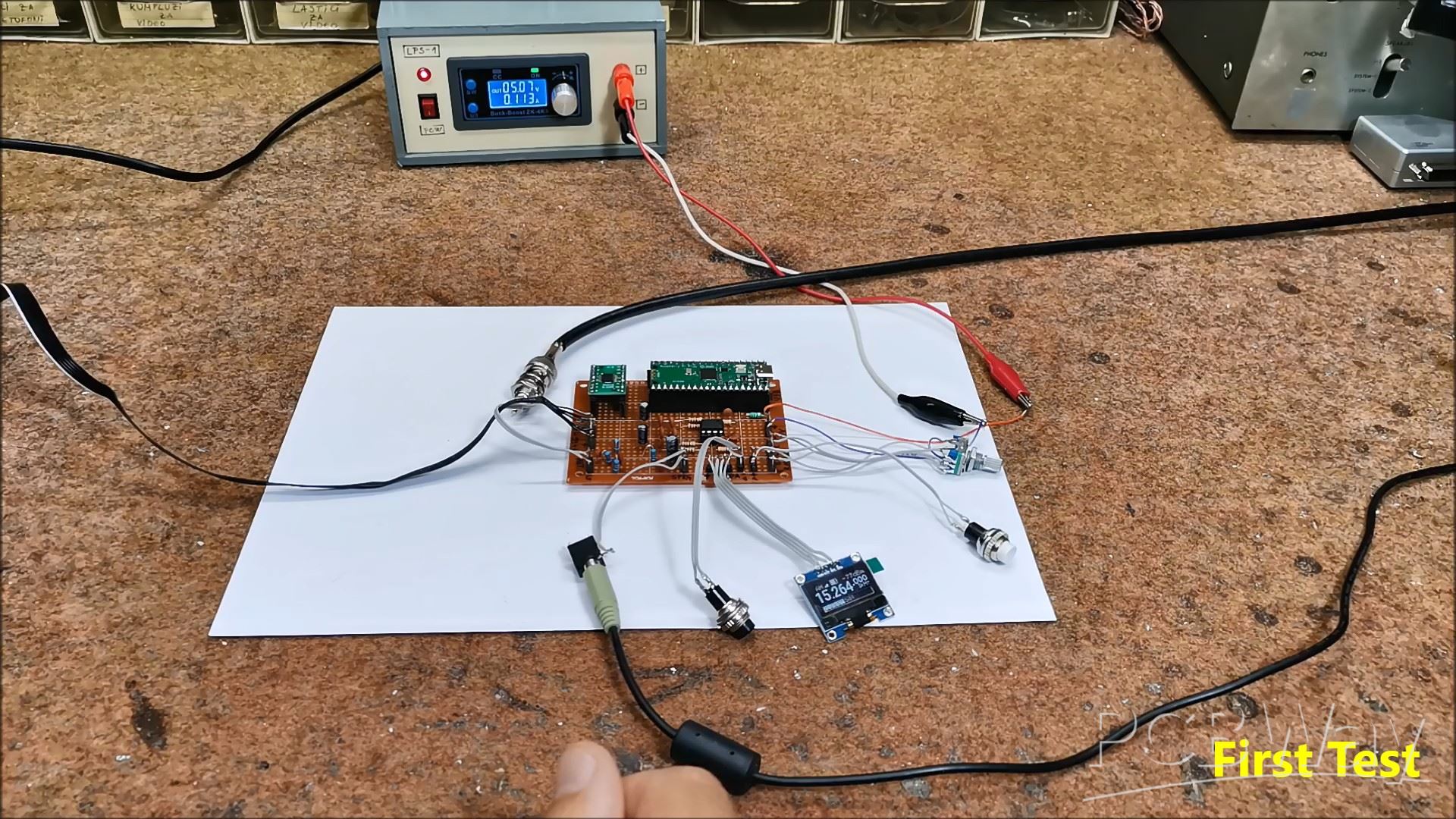
Now comes the first power-up of the device and a short test. I connected the audio output from the receiver to the "Line In" input of the PC sound card. For now, I connect a simple "long wire" antenna and try to receive a Broadcast station to confirm the functionality.
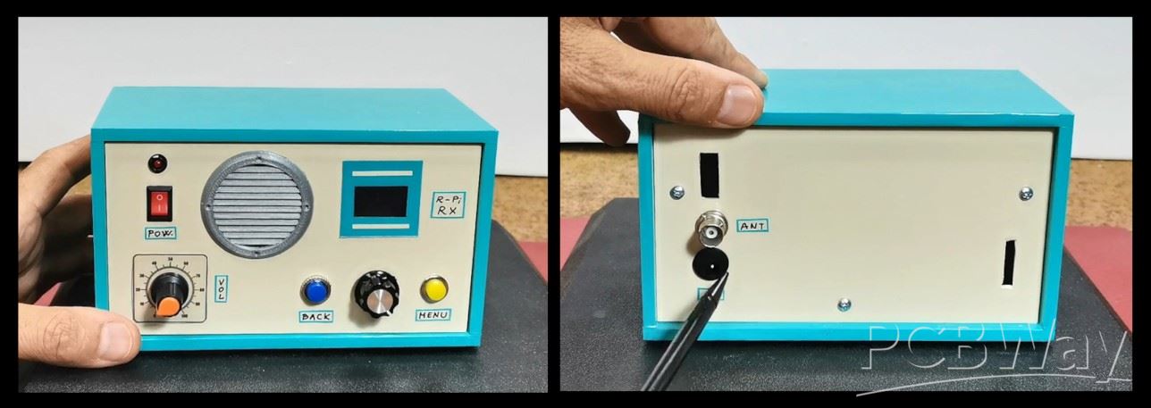
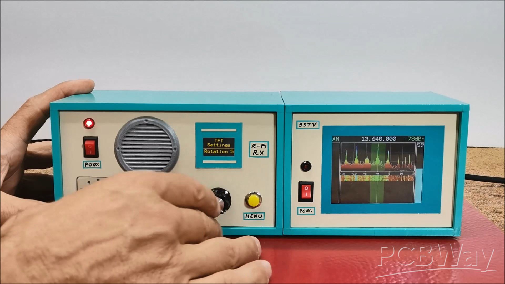
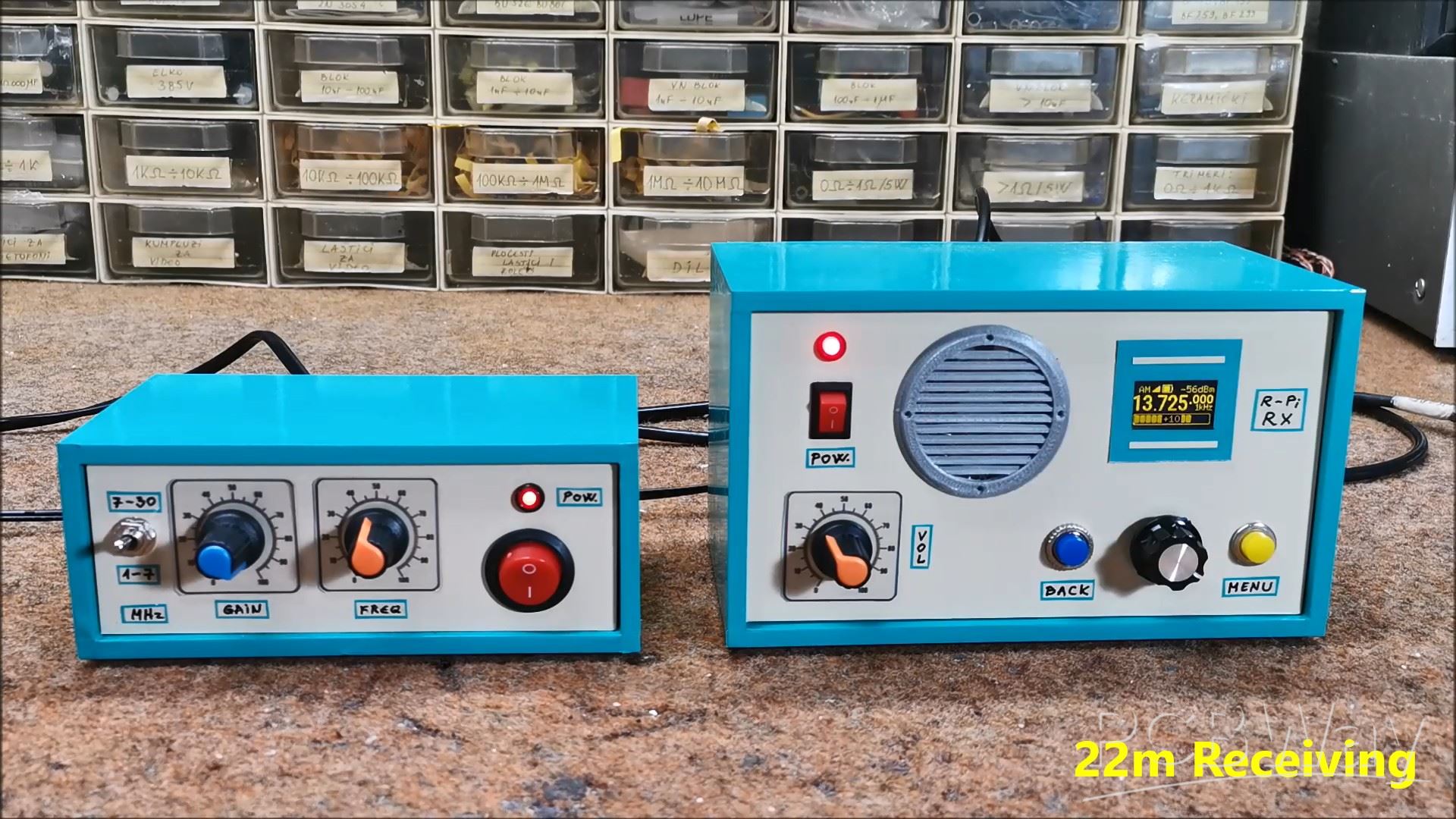
This is what the finished Pico SDR Receiver looks like placed in a suitable housing with the Display and control buttons on the front panel and the power and antenna connection on the back.
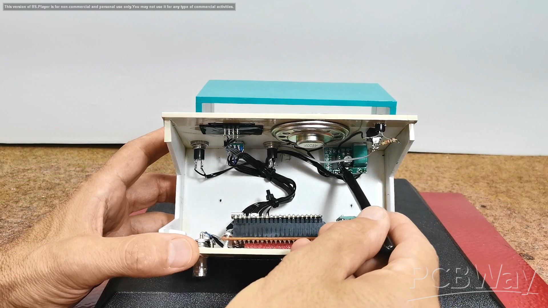
If we look inside the box we will see that in addition to the universal PCB it also have a D-class Audio Amplifier module along with a small speaker so the SDR receiver is completely independent keeping in mind that instead of an external power supply we can install Lithium batteries with charger circuit.
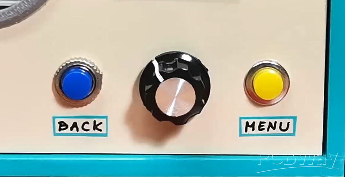
Now I will just briefly "walk" through the menu to look at all the functions and possibilities. To explain all these functions individually would take us a really long time. At the end of this text is the original manual according to which you can study all the functions in more detail. For setting the options we have two buttons MENU and BACK plus Rotary encoder with built-in button.
When turning on the receiver, the display shows the information that has been saved since the last operation.
Even at the start, on this small display it has many useful functions:
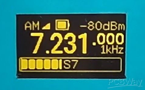
- In the middle is shown the current tuning frequency with large numbers
- Then the demodulation mode, in this case AM
- Battery status
- Signal strength in dBm
- Signal strength in the form of a bar
- as well as the tuning step
By pressing the left button we move through several interesting display modes:
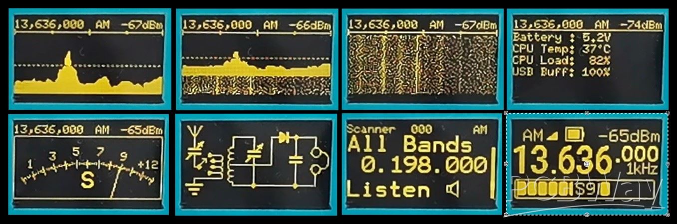
- Spectrum display
- Then spectrum plus waterfall
- then just waterfall
- data about the battery and resources of the microcontroller
- Next comes a beautiful Analog Signal Strength Meter
- Schematic of a simple detector receiver as a screensaver
- and finally we return to the home screen
With the Rotary encoder, we set the desired frequency with a tuning step that we can also adjust.

By pressing the rotary knob, we enter the menu where we can select the appropriate BAND, and by pressing it again, we activate the selected BAND.
With the right MENU button we enter the main menu where we can perform detailed settings of the received signal. With the rotary encoder we move through the menu and select the set value, and by pressing it again we confirm the selected value.
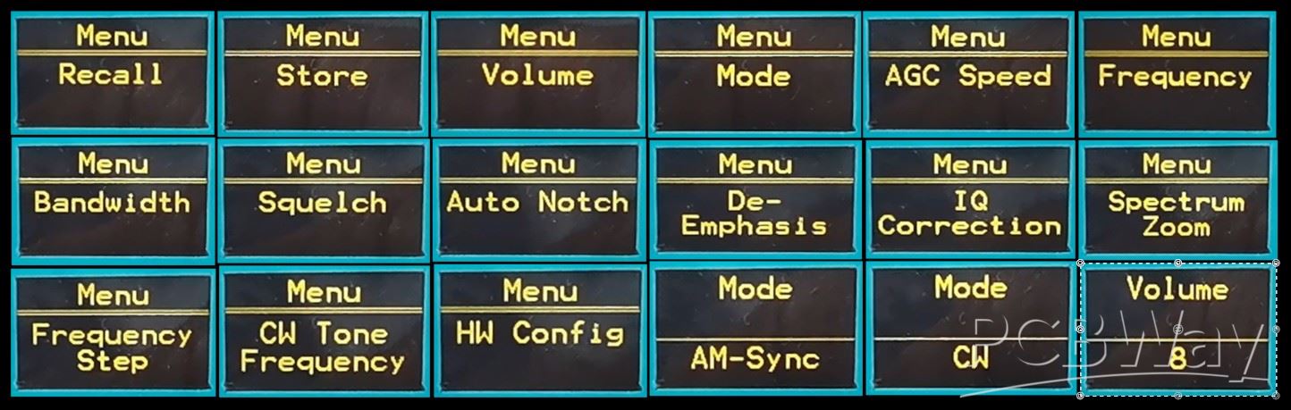
In the Menu we have the following options:
-Frequency
-Recall of stored data
- Frequency storage
- Volume value (0 to 9)
- MODE (AM, AM-Sync, LSB, USB, FM, and CW)
- AGC speed ()
- Bandwidth ()
- Squelch
- Auto NOTCH (On or OFF)
- DE-Emphasis
- IQ correction
- Band Strat and Band Sop for scan function
- Frequency setup
- CW Tone frequency
- And finally Hardware settings
We also have more additional functions and shortcuts by pressing the three buttons in combination.
While working on the project, to my great surprise I accidentally noticed that this small SDR radio even has the option of an additional larger color display that shows the spectrum with a waterfall. The code already supports this option and we just need to add the additional display to the menu. I am currently using the case with the display mounted from a previous project of mine, but it would be even better if both displays were mounted in a larger common case.
With this visual addition, this beautiful little radio becomes even more attractive. Below is the diagram for connecting the display, with a Raspberry Pi pico and I did it with a soft flat cable.
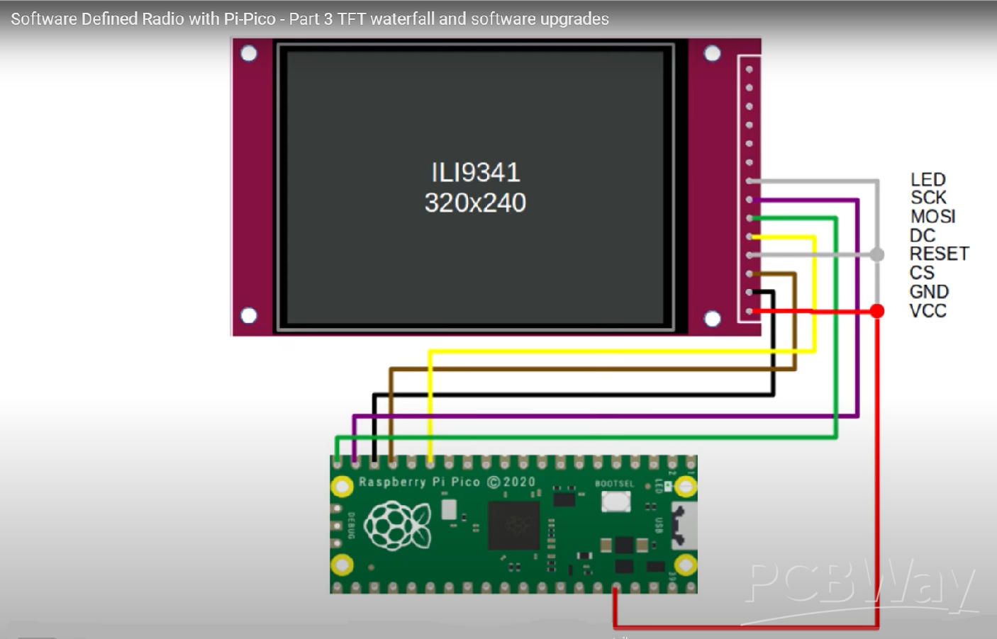
Now we need to enable second display in the Hardware menu, and set the rotation and colour.
Next I will demonstrate the reception of Broadcast stations and Amateur radio communications. As you can see, the reception is relatively poor. The reason for this is the fact that in this basic version the receiver does not contain any filter circuits at the input, and also does not have a Low Noise Amplifier that such devices usually have. Also, for the antenna I used a simple 5m wire placed on the roof of my house. In one case I used my antenna tuner and the reception was significantly better.
And finally, a short conclusion. I really have no words to describe this great project. I thank Jon Dawson for the hard work he put into it and I hope that in the future, with the support of the community, this project will develop even more. This project demonstrates the incredible potential of software-defined radio, transforming a few simple components into a powerful and flexible communication tool. I encourage you to build your own and explore the world of radio in a whole new way. It's truly remarkable to see how a simple Raspberry Pi Pico, with a bit of code, can unlock such a wide range of radio functions. I hope this video inspires you to get hands-on and join the ever-growing community of SDR enthusiasts.
Build a Raspberry Pi Pico SDR Radio with Waterfall Display


Raspberry Pi 5 7 Inch Touch Screen IPS 1024x600 HD LCD HDMI-compatible Display for RPI 4B 3B+ OPI 5 AIDA64 PC Secondary Screen(Without Speaker)
BUY NOW


- Comments(1)
- Likes(4)
More by Mirko Pavleski
-
 Arduino 3D Printed self Balancing Cube
Self-balancing devices are electronic devices that use sensors and motors to keep themselves balanc...
Arduino 3D Printed self Balancing Cube
Self-balancing devices are electronic devices that use sensors and motors to keep themselves balanc...
-
 Elecrow All-in-One Arduino Starter Kit Review - 20 Projects & 16 Modules
This time I will describe a simple and practical way to enter the world of microcontrollers, specif...
Elecrow All-in-One Arduino Starter Kit Review - 20 Projects & 16 Modules
This time I will describe a simple and practical way to enter the world of microcontrollers, specif...
-
 ESP32-C3 Color Detector with TCS34725, Real-Time RGB Detection & Web Interface
Color detection is a fundamental task in many embedded systems – from industrial sorting machines t...
ESP32-C3 Color Detector with TCS34725, Real-Time RGB Detection & Web Interface
Color detection is a fundamental task in many embedded systems – from industrial sorting machines t...
-
 DIY ESP32 Telegram Flood Protection System - Smart Home Automation
Recently I had an unpleasant experience in my home, specifically my ground floor was flooded as a r...
DIY ESP32 Telegram Flood Protection System - Smart Home Automation
Recently I had an unpleasant experience in my home, specifically my ground floor was flooded as a r...
-
 Real-Time Air Traffic Radar using ESP32 + ADS-B Data
ADS-B, which stands for Automatic Dependent Surveillance-Broadcast, is the modern standard for trac...
Real-Time Air Traffic Radar using ESP32 + ADS-B Data
ADS-B, which stands for Automatic Dependent Surveillance-Broadcast, is the modern standard for trac...
-
 DIY Green Laser Night Sky Object Finder - Find Stars & Galaxies Instantly with great accuracy
As an amateur astronomer, especially at the beginning, the most difficult part of observing the nig...
DIY Green Laser Night Sky Object Finder - Find Stars & Galaxies Instantly with great accuracy
As an amateur astronomer, especially at the beginning, the most difficult part of observing the nig...
-
 DIY Avionics Simulator with ESP32 - Artificial Horizon, Compass & Altimeter
The inspiration for this project comes from classical aircraft cockpit instruments used for navigat...
DIY Avionics Simulator with ESP32 - Artificial Horizon, Compass & Altimeter
The inspiration for this project comes from classical aircraft cockpit instruments used for navigat...
-
 DIY Miniature X-Ray Machine using a TV Vacuum Tube DY86
An X-ray machine (or radiograph) is a quick, painless medical test that produces images of the struc...
DIY Miniature X-Ray Machine using a TV Vacuum Tube DY86
An X-ray machine (or radiograph) is a quick, painless medical test that produces images of the struc...
-
 Simple SDR Receiver Using 2x NE612 - Dual Conversion, Superheterodyne (0.1–30 MHz)
SDR (Software Defined Radio) is a radio system in which most of the functions of a classic radio (f...
Simple SDR Receiver Using 2x NE612 - Dual Conversion, Superheterodyne (0.1–30 MHz)
SDR (Software Defined Radio) is a radio system in which most of the functions of a classic radio (f...
-
 DIY Vintage TV VU Meter with peak indicators
Some time ago in one of my projects I presented you a way to turn a black and white old mini TV int...
DIY Vintage TV VU Meter with peak indicators
Some time ago in one of my projects I presented you a way to turn a black and white old mini TV int...
-
 DIY Tesla Coil based Plasma Rife Machine
In several of my previous videos, I presented you with different ways to make a Rife Machine, from ...
DIY Tesla Coil based Plasma Rife Machine
In several of my previous videos, I presented you with different ways to make a Rife Machine, from ...
-
 ESP32 Analog VU Meter – Smooth Needle, Real Audio Response (DIY Build)
In several of my previous videos I have shown you how to make analog VU meters emulated on differen...
ESP32 Analog VU Meter – Smooth Needle, Real Audio Response (DIY Build)
In several of my previous videos I have shown you how to make analog VU meters emulated on differen...
-
 The Ultimate Smartphone VFO ESP32 & Si5351 Wireless Control
Variable frequency oscillators (VFOs) are commonly used in radio transmitters and receivers, especi...
The Ultimate Smartphone VFO ESP32 & Si5351 Wireless Control
Variable frequency oscillators (VFOs) are commonly used in radio transmitters and receivers, especi...
-
 DIY Shortwave Propagation Monitor - Measure Ionosphere Conditions
Shortwave Propagation is the way radio waves in the 3 to 30 MHz range travel from point A to point ...
DIY Shortwave Propagation Monitor - Measure Ionosphere Conditions
Shortwave Propagation is the way radio waves in the 3 to 30 MHz range travel from point A to point ...
-
 Professional grade Smart Lock with ESP32, BLE and Android App Control
An electronic codelock is a security device that grants access using a numerical sequence—a PIN cod...
Professional grade Smart Lock with ESP32, BLE and Android App Control
An electronic codelock is a security device that grants access using a numerical sequence—a PIN cod...
-
 Building a 3-Input Stereo ECC83 (12AX7) Tube Preamp
Some time ago I presented you a project for a 3W stereo tube amplifier with a GU32 output vacuum t...
Building a 3-Input Stereo ECC83 (12AX7) Tube Preamp
Some time ago I presented you a project for a 3W stereo tube amplifier with a GU32 output vacuum t...
-
 ESP32 Weather Dashboard with Satellite Maps and 16-day Weather Forecast
As you can see from my previous videos, besides Electronics, my fields of experimentation and proje...
ESP32 Weather Dashboard with Satellite Maps and 16-day Weather Forecast
As you can see from my previous videos, besides Electronics, my fields of experimentation and proje...
-
 Retro Analog VU Meter on Round dispalys (ESP32 and GC9A01)
Recently, in one of my previous videos I presented you a Retro VU Meter project on round displays ...
Retro Analog VU Meter on Round dispalys (ESP32 and GC9A01)
Recently, in one of my previous videos I presented you a Retro VU Meter project on round displays ...
-
Programmable Mist Maker - XIAO / QT PY Extension
1060 2 1 -
RadioHAT - Raspberry Pi radio development platform
858 0 2 -
-
-
-
-
ARPS-2 – Arduino-Compatible Robot Project Shield for Arduino UNO
3320 0 6 -
A Compact Charging Breakout Board For Waveshare ESP32-C3
3926 3 8 -
AI-driven LoRa & LLM-enabled Kiosk & Food Delivery System
4314 2 2


