


|
|
Arduino Nano R3 |
x 1 | |
|
|
WS2812 Addressable LED Strip |
x 1 | |
|
|
Transistor NPN |
x 1 | |
|
|
Rotary potentiometer |
x 2 | |
|
|
Pushbutton |
x 4 | |
|
|
Buzzer |
x 1 |

|
Soldering Iron Kit |
|

|
arduino IDEArduino
|
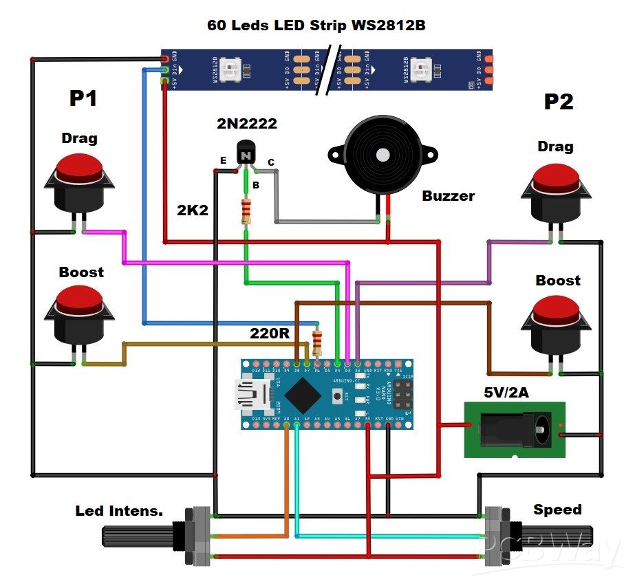
Tug of War Arduino Game on WS2812 Led strip
A Tug of War is a classic team-based game where two opposing teams compete to pull a rope in opposite directions. The objective is to pull the other team across a certain marker (often a line or flag) positioned in the center of the rope.

This time I will describe how to make an Arduino version of this game for two players. In fact, each player represents a team and has its own color. Thanks to the LED strip with programmable RGB LEDs with a built-in WS 2812 chip we can make this game in a very simple way.
To make the game, we only need a few components:
- Arduino Nano microcontroller board
- Led Strip with 60RGB leds with built-in WS2812 chip
- Four buttons
- NPN Transistor
- Two potentiometyers 10K
- Two resistors
- and Buzzer

This project is sponsored by Altium 365 . Altium 365 is a cloud-based platform designed for electronics design and engineering. It provides a suite of tools for PCB design tools, including Requipments management, Supply chain, Library managment, ECAD connectivity, Co-design and integration, and manufacturing port

I'm actually using the box from a previous project of mine that used 4 buttons and two potentiometers, so I used the same hardware configuration, and the game even got more features and became more interesting to play. First, before I start playing, let me explain all the functions and how to play. Immediately after turning on the game, the two LEDs in the middle of the strip are activated, twice with red color, and the third time with magenta, which indicates the start of the game. This part is accompanied by appropriate sounds. Then, on both sides of these two LEDs, the remaining LEDs light up with the characteristic color for each player, in this case blue for Player1 and yellow for Player2.

The starting diode, seen from both sides, is magenta, and this is the limit to which we have to pull the opposing player. The movement of each player is indicated by beeps with different frequencies. Two red LEDs in the middle are actually the flag that shows the current position of the players. When this flag reaches one of the magenta LEDs, victory is declared for that player, in a way that all LEDs light up and flash three times with the color of the winner, of course by emitting appropriate sounds.

After the game ends, after a few seconds a new game starts in the way I explained previously. The two main buttons are used to pull the rope and the strength of the pull is proportional to the speed of pressing these buttons. The player who presses faster pulls the flag to his side. The second BOOST buttons, as the name suggests, are used to pull the rope with double strength and these buttons can only be used once during a specific game. The use of the BOOST button is signaled by a brief flashing of the magenta LEDs on the corresponding side of the player who used it.

Therefore, we need to think carefully at what point to use these buttons, which also gives the game a strategic component. When testing the game, I noticed that if the typing speed of both players is approximately the same, the game lasts a very long time and becomes boring. To avoid this moment, I used the first potentiometer to regulate the speed of movement of the rope, in 5 steps continuously. Here is what the movement looks like in the lowest and highest pulling speed. I used the second potentiometer to regulate the intensity of the LEDs, which is actually a very useful option that allows the device to adapt to operating in different conditions, for example, day and night.
As you can see, the Arduino code may not be fully optimized, but it is relatively understandable, so you can easily make changes to it according to your own ideas, especially in terms of changing colors, sounds, and speed.

Now I will demonstrate to you what the gameplay looks like, noting that I will represent both players, and in a real game with different players, the gameplay is far more interesting and even addictive.

And finally a short conclusion. This is an interesting simple to make Arduino game that can be made in less than a day. The simplicity is due to the LED strip consisting of 60 special LEDs with built-in chips, so at any moment we have full control of each LED individually thanks to the Adafruit_NeoPixel library. The device is built into a suitable box made of PVC material, and covered with colored self-adhesive wallpaper. The power supply is 5V and a minimum current of 1A.

#include <Adafruit_NeoPixel.h>

// Pin definitions
#define LED_PIN 6
#define BUTTON1_PIN 2        // Player 1 button
#define BUTTON2_PIN 3        // Player 2 button
#define BUZZER_PIN 4         // Buzzer pin
#define LED_INTENSITY_POT A0 // Potentiometer for LED brightness
#define SPEED_POT A1        // Potentiometer for game speed
#define POWER1_PIN 7        // Player 1 power move button
#define POWER2_PIN 8        // Player 2 power move button

// LED strip configuration
#define NUM_LEDS 60         // Total number of LEDs (29 + 2 + 29)
#define CENTER_POS 30       // Center position (0-based index)

// Game constants
#define DEBOUNCE_TIME 50    // Button debounce time in milliseconds
#define VICTORY_FLASHES 3   // Number of victory flashes
#define FLASH_DELAY 200     // Delay between flashes in milliseconds
#define MIN_CLICK_SPEED 1   // Minimum pixels to move per click
#define MAX_CLICK_SPEED 5   // Maximum pixels to move per click

// Power move constants
#define POWER_BOOST 3       // Fixed amount added to speed during power move
#define POWER_MOVES_COUNT 3 // Number of powered moves each player gets
#define POWER_FLASH_DURATION 500 // Duration of power move activation flash
#define MAX_POWER_SPEED (MAX_CLICK_SPEED + 2) // Maximum speed during power move

// Initialize LED strip
Adafruit_NeoPixel strip = Adafruit_NeoPixel(NUM_LEDS, LED_PIN, NEO_GRB + NEO_KHZ800);

// Colors
uint32_t COLOR_RED;
uint32_t COLOR_BLUE;
uint32_t COLOR_YELLOW;
uint32_t COLOR_MAGENTA;
const uint32_t COLOR_OFF = strip.Color(0, 0, 0);

// Game state variables
int flagPosition = CENTER_POS;  // Current position of the center of the red flag
unsigned long lastButton1Press = 0;
unsigned long lastButton2Press = 0;
bool gameActive = false;  // Changed to false initially
int clickSpeed = 1;      // Number of pixels to move per click

// Power move state variables
bool player1PowerActive = false;
bool player2PowerActive = false;
int player1PowerMovesLeft = 0;
int player2PowerMovesLeft = 0;
bool player1PowerAvailable = true;  // Can only use once per round
bool player2PowerAvailable = true;  // Can only use once per round
unsigned long lastPower1Press = 0;
unsigned long lastPower2Press = 0;

bool button1LastState = HIGH;
bool button2LastState = HIGH;
bool power1LastState = HIGH;
bool power2LastState = HIGH;

void setup() {
  // Initialize LED strip
  strip.begin();
  strip.show();

  // Set up buttons with internal pull-up resistors
  pinMode(BUTTON1_PIN, INPUT_PULLUP);
  pinMode(BUTTON2_PIN, INPUT_PULLUP);
  pinMode(POWER1_PIN, INPUT_PULLUP);
  pinMode(POWER2_PIN, INPUT_PULLUP);
  pinMode(BUZZER_PIN, OUTPUT);
  pinMode(LED_INTENSITY_POT, INPUT);
  pinMode(SPEED_POT, INPUT);

    button1LastState = digitalRead(BUTTON1_PIN);
    button2LastState = digitalRead(BUTTON2_PIN);
    power1LastState = digitalRead(POWER1_PIN);
    power2LastState = digitalRead(POWER2_PIN);

  // Initial game state
  resetGame();
}

void loop() {
  if (!gameActive) {
    playStartSequence();
  }

  if (gameActive) {
    // Update LED brightness based on potentiometer
    updateColors();

    // Update game speed based on potentiometer
    updateGameSpeed();

    // Check for power moves
    checkPowerMoves();

    // Check for button presses with debounce
    checkButtons();
    updateLEDs();
  }
}

void checkPowerMoves() {
    // Read current power button states
    bool power1CurrentState = digitalRead(POWER1_PIN);
    bool power2CurrentState = digitalRead(POWER2_PIN);

    // Check Player 1 power move button
    if (power1CurrentState == LOW && power1LastState == HIGH) {  // Detect only falling edge
        if (millis() - lastPower1Press > DEBOUNCE_TIME && player1PowerAvailable) {
            activatePowerMove(1);
            lastPower1Press = millis();
        }
    }

    // Check Player 2 power move button
    if (power2CurrentState == LOW && power2LastState == HIGH) {  // Detect only falling edge
        if (millis() - lastPower2Press > DEBOUNCE_TIME && player2PowerAvailable) {
            activatePowerMove(2);
            lastPower2Press = millis();
        }
    }

        // Update power button states
    power1LastState = power1CurrentState;
    power2LastState = power2CurrentState;
}

void activatePowerMove(int player) {
    if (player == 1 && player1PowerAvailable) {
        player1PowerActive = true;
        player1PowerMovesLeft = POWER_MOVES_COUNT;
        player1PowerAvailable = false;
        flashPowerMove(1);
    } else if (player == 2 && player2PowerAvailable) {
        player2PowerActive = true;
        player2PowerMovesLeft = POWER_MOVES_COUNT;
        player2PowerAvailable = false;
        flashPowerMove(2);
    }
}

void flashPowerMove(int player) {
    strip.clear();
    // Flash player's side
    if (player == 1) {
        for (int i = 0; i < CENTER_POS; i++) {
            strip.setPixelColor(i, COLOR_MAGENTA);
        }
        tone(BUZZER_PIN, 2000, 200); // Power move activation sound
    } else {
        for (int i = CENTER_POS; i < NUM_LEDS; i++) {
            strip.setPixelColor(i, COLOR_MAGENTA);
        }
        tone(BUZZER_PIN, 2500, 200); // Power move activation sound
    }
    strip.show();
    delay(POWER_FLASH_DURATION);
    updateLEDs();
}

void playStartSequence() {
  // First update colors for the sequence
  updateColors();

  // Flash center position in preparation
  for (int i = 0; i < 3; i++) {
    // First two beeps with one frequency
    if (i < 2) {
      strip.clear();
      strip.setPixelColor(CENTER_POS, COLOR_RED);
      strip.setPixelColor(CENTER_POS - 1, COLOR_RED);
      strip.show();
      tone(BUZZER_PIN, 800, 200);  // Lower frequency for ready beeps
      delay(300);

      strip.clear();
      strip.show();
      delay(300);
    }
    // Final beep with different frequency
    else {
      strip.clear();
      strip.setPixelColor(CENTER_POS, COLOR_MAGENTA);
      strip.setPixelColor(CENTER_POS - 1, COLOR_MAGENTA);
      strip.show();
      tone(BUZZER_PIN, 1200, 400);  // Higher frequency for start beep
      delay(400);
    }
  }

  // Start the game
  gameActive = true;
  flagPosition = CENTER_POS;
  updateLEDs();
}

void updateColors() {
  // Read LED intensity from potentiometer (0-255)
  int intensity = map(analogRead(LED_INTENSITY_POT), 0, 1023, 0, 255);

  // Update colors with new intensity
  COLOR_RED = strip.Color(intensity, 0, 0);
  COLOR_BLUE = strip.Color(0, 0, intensity);
  COLOR_YELLOW = strip.Color(intensity, intensity, 0);
  COLOR_MAGENTA = strip.Color(intensity, 0, intensity);
}

void updateGameSpeed() {
  // Read speed value from potentiometer
  clickSpeed = map(analogRead(SPEED_POT), 0, 1023, MIN_CLICK_SPEED, MAX_CLICK_SPEED);
}

void checkButtons() {
    // Read current button states
    bool button1CurrentState = digitalRead(BUTTON1_PIN);
    bool button2CurrentState = digitalRead(BUTTON2_PIN);

    // Check Player 1 button (pulls flag left)
    if (button1CurrentState == LOW && button1LastState == HIGH) {  // Detect only falling edge
        if (millis() - lastButton1Press > DEBOUNCE_TIME) {
            // Calculate move amount with a more balanced power multiplier
            int moveAmount = clickSpeed;
            if (player1PowerActive && player1PowerMovesLeft > 0) {
                moveAmount = min(moveAmount + POWER_BOOST, MAX_POWER_SPEED);
                player1PowerMovesLeft--;
                if (player1PowerMovesLeft <= 0) {
                    player1PowerActive = false;
                }
            }
            flagPosition -= moveAmount;
            tone(BUZZER_PIN, player1PowerActive ? 800 : 1000, 20);
            lastButton1Press = millis();
        }
    }

    // Check Player 2 button (pulls flag right)
    if (button2CurrentState == LOW && button2LastState == HIGH) {  // Detect only falling edge
        if (millis() - lastButton2Press > DEBOUNCE_TIME) {
            int moveAmount = clickSpeed;
            if (player2PowerActive && player2PowerMovesLeft > 0) {
                moveAmount = min(moveAmount + POWER_BOOST, MAX_POWER_SPEED);
                player2PowerMovesLeft--;
                if (player2PowerMovesLeft <= 0) {
                    player2PowerActive = false;
                }
            }
            flagPosition += moveAmount;
            tone(BUZZER_PIN, player2PowerActive ? 1300 : 1500, 20);
            lastButton2Press = millis();
        }
    }

    // Update button states
    button1LastState = button1CurrentState;
    button2LastState = button2CurrentState;

    // Keep flag position within bounds
    flagPosition = constrain(flagPosition, 1, NUM_LEDS - 2);

    // Check for victory conditions
    if (flagPosition <= 1 || flagPosition >= NUM_LEDS - 2) {
        gameActive = false;
        celebrateVictory();
    }
}

void updateLEDs() {
  strip.clear();

  // Draw the red flag (2 LEDs)
  strip.setPixelColor(flagPosition, COLOR_RED);
  strip.setPixelColor(flagPosition - 1, COLOR_RED);

  // Draw Player 1 side (blue)
  for (int i = 0; i < flagPosition - 1; i++) {
    strip.setPixelColor(i, i == 0 ? COLOR_MAGENTA : COLOR_BLUE);
  }

  // Draw Player 2 side (yellow)
  for (int i = flagPosition + 1; i < NUM_LEDS; i++) {
    strip.setPixelColor(i, i == NUM_LEDS - 1 ? COLOR_MAGENTA : COLOR_YELLOW);
  }

  strip.show();
}

void celebrateVictory() {
  // Determine winner's color
  uint32_t winnerColor = (flagPosition <= 1) ? COLOR_BLUE : COLOR_YELLOW;

  // Victory tune
  if (flagPosition <= 1) {
    playVictoryTune(1000);  // Lower pitch for Player 1
  } else {
    playVictoryTune(1500);  // Higher pitch for Player 2
  }

  // Flash victory animation
  for (int i = 0; i < VICTORY_FLASHES; i++) {
    // Fill with winner's color
    for (int j = 0; j < NUM_LEDS; j++) {
      strip.setPixelColor(j, winnerColor);
    }
    strip.show();
    delay(FLASH_DELAY);

    // Turn off
    strip.clear();
    strip.show();
    delay(FLASH_DELAY);
  }

  delay(3000);
  resetGame();
}

void playVictoryTune(int baseFreq) {
  tone(BUZZER_PIN, baseFreq, 200);
  delay(200);
  tone(BUZZER_PIN, baseFreq * 1.25, 200);
  delay(200);
  tone(BUZZER_PIN, baseFreq * 1.5, 400);
  delay(400);
}

void resetGame() {
    flagPosition = CENTER_POS;
    gameActive = false;
    player1PowerActive = false;
    player2PowerActive = false;
    player1PowerMovesLeft = 0;
    player2PowerMovesLeft = 0;
    player1PowerAvailable = true;
    player2PowerAvailable = true;
    updateLEDs();
}
Tug of War Arduino Game on WS2812 Led strip


Raspberry Pi 5 7 Inch Touch Screen IPS 1024x600 HD LCD HDMI-compatible Display for RPI 4B 3B+ OPI 5 AIDA64 PC Secondary Screen(Without Speaker)
BUY NOW


- Comments(0)
- Likes(0)
More by Mirko Pavleski
-
 Arduino 3D Printed self Balancing Cube
Self-balancing devices are electronic devices that use sensors and motors to keep themselves balanc...
Arduino 3D Printed self Balancing Cube
Self-balancing devices are electronic devices that use sensors and motors to keep themselves balanc...
-
 Elecrow All-in-One Arduino Starter Kit Review - 20 Projects & 16 Modules
This time I will describe a simple and practical way to enter the world of microcontrollers, specif...
Elecrow All-in-One Arduino Starter Kit Review - 20 Projects & 16 Modules
This time I will describe a simple and practical way to enter the world of microcontrollers, specif...
-
 ESP32-C3 Color Detector with TCS34725, Real-Time RGB Detection & Web Interface
Color detection is a fundamental task in many embedded systems – from industrial sorting machines t...
ESP32-C3 Color Detector with TCS34725, Real-Time RGB Detection & Web Interface
Color detection is a fundamental task in many embedded systems – from industrial sorting machines t...
-
 DIY ESP32 Telegram Flood Protection System - Smart Home Automation
Recently I had an unpleasant experience in my home, specifically my ground floor was flooded as a r...
DIY ESP32 Telegram Flood Protection System - Smart Home Automation
Recently I had an unpleasant experience in my home, specifically my ground floor was flooded as a r...
-
 Real-Time Air Traffic Radar using ESP32 + ADS-B Data
ADS-B, which stands for Automatic Dependent Surveillance-Broadcast, is the modern standard for trac...
Real-Time Air Traffic Radar using ESP32 + ADS-B Data
ADS-B, which stands for Automatic Dependent Surveillance-Broadcast, is the modern standard for trac...
-
 DIY Green Laser Night Sky Object Finder - Find Stars & Galaxies Instantly with great accuracy
As an amateur astronomer, especially at the beginning, the most difficult part of observing the nig...
DIY Green Laser Night Sky Object Finder - Find Stars & Galaxies Instantly with great accuracy
As an amateur astronomer, especially at the beginning, the most difficult part of observing the nig...
-
 DIY Avionics Simulator with ESP32 - Artificial Horizon, Compass & Altimeter
The inspiration for this project comes from classical aircraft cockpit instruments used for navigat...
DIY Avionics Simulator with ESP32 - Artificial Horizon, Compass & Altimeter
The inspiration for this project comes from classical aircraft cockpit instruments used for navigat...
-
 DIY Miniature X-Ray Machine using a TV Vacuum Tube DY86
An X-ray machine (or radiograph) is a quick, painless medical test that produces images of the struc...
DIY Miniature X-Ray Machine using a TV Vacuum Tube DY86
An X-ray machine (or radiograph) is a quick, painless medical test that produces images of the struc...
-
 Simple SDR Receiver Using 2x NE612 - Dual Conversion, Superheterodyne (0.1–30 MHz)
SDR (Software Defined Radio) is a radio system in which most of the functions of a classic radio (f...
Simple SDR Receiver Using 2x NE612 - Dual Conversion, Superheterodyne (0.1–30 MHz)
SDR (Software Defined Radio) is a radio system in which most of the functions of a classic radio (f...
-
 DIY Vintage TV VU Meter with peak indicators
Some time ago in one of my projects I presented you a way to turn a black and white old mini TV int...
DIY Vintage TV VU Meter with peak indicators
Some time ago in one of my projects I presented you a way to turn a black and white old mini TV int...
-
 DIY Tesla Coil based Plasma Rife Machine
In several of my previous videos, I presented you with different ways to make a Rife Machine, from ...
DIY Tesla Coil based Plasma Rife Machine
In several of my previous videos, I presented you with different ways to make a Rife Machine, from ...
-
 ESP32 Analog VU Meter – Smooth Needle, Real Audio Response (DIY Build)
In several of my previous videos I have shown you how to make analog VU meters emulated on differen...
ESP32 Analog VU Meter – Smooth Needle, Real Audio Response (DIY Build)
In several of my previous videos I have shown you how to make analog VU meters emulated on differen...
-
 The Ultimate Smartphone VFO ESP32 & Si5351 Wireless Control
Variable frequency oscillators (VFOs) are commonly used in radio transmitters and receivers, especi...
The Ultimate Smartphone VFO ESP32 & Si5351 Wireless Control
Variable frequency oscillators (VFOs) are commonly used in radio transmitters and receivers, especi...
-
 DIY Shortwave Propagation Monitor - Measure Ionosphere Conditions
Shortwave Propagation is the way radio waves in the 3 to 30 MHz range travel from point A to point ...
DIY Shortwave Propagation Monitor - Measure Ionosphere Conditions
Shortwave Propagation is the way radio waves in the 3 to 30 MHz range travel from point A to point ...
-
 Professional grade Smart Lock with ESP32, BLE and Android App Control
An electronic codelock is a security device that grants access using a numerical sequence—a PIN cod...
Professional grade Smart Lock with ESP32, BLE and Android App Control
An electronic codelock is a security device that grants access using a numerical sequence—a PIN cod...
-
 Building a 3-Input Stereo ECC83 (12AX7) Tube Preamp
Some time ago I presented you a project for a 3W stereo tube amplifier with a GU32 output vacuum t...
Building a 3-Input Stereo ECC83 (12AX7) Tube Preamp
Some time ago I presented you a project for a 3W stereo tube amplifier with a GU32 output vacuum t...
-
 ESP32 Weather Dashboard with Satellite Maps and 16-day Weather Forecast
As you can see from my previous videos, besides Electronics, my fields of experimentation and proje...
ESP32 Weather Dashboard with Satellite Maps and 16-day Weather Forecast
As you can see from my previous videos, besides Electronics, my fields of experimentation and proje...
-
 Retro Analog VU Meter on Round dispalys (ESP32 and GC9A01)
Recently, in one of my previous videos I presented you a Retro VU Meter project on round displays ...
Retro Analog VU Meter on Round dispalys (ESP32 and GC9A01)
Recently, in one of my previous videos I presented you a Retro VU Meter project on round displays ...
-
Programmable Mist Maker - XIAO / QT PY Extension
1112 2 1 -
RadioHAT - Raspberry Pi radio development platform
920 0 2 -
-
-
-
-
ARPS-2 – Arduino-Compatible Robot Project Shield for Arduino UNO
3358 0 6 -
A Compact Charging Breakout Board For Waveshare ESP32-C3
3968 3 8 -
AI-driven LoRa & LLM-enabled Kiosk & Food Delivery System
4357 2 2


