


|
arduino IDEArduino
|
|

|
KiCad 9.0 |
|

|
Soldering iron (generic) |
|

|
Soldering Iron Wire |
|

|
Google Sheets |
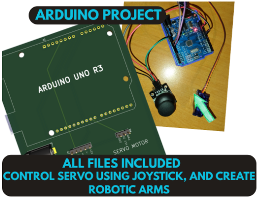
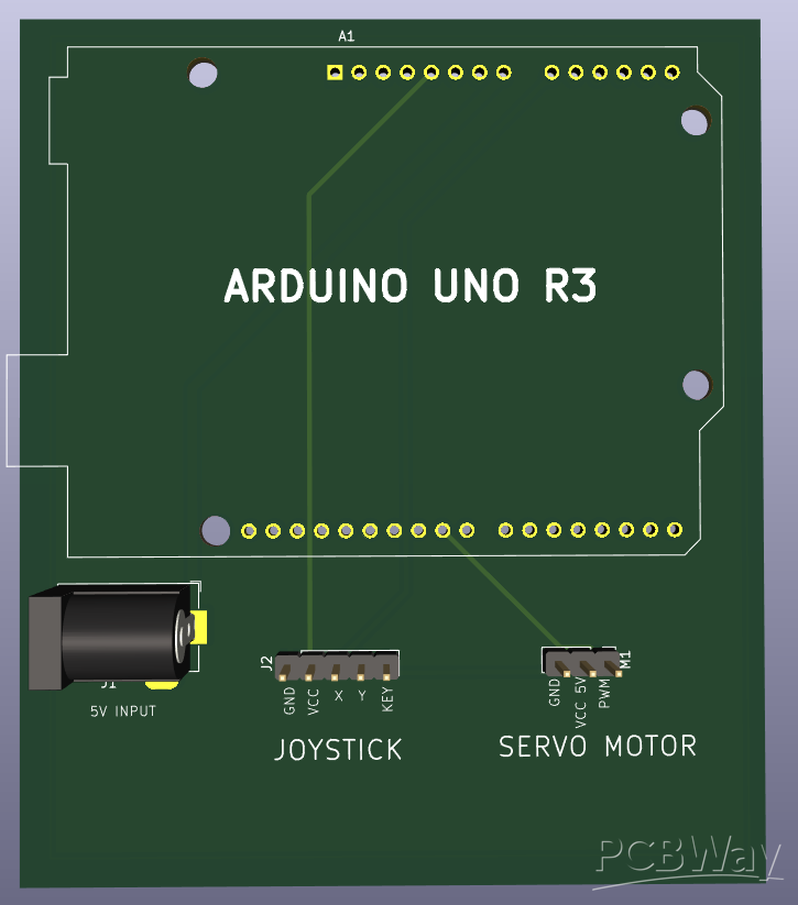
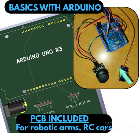
Learn basics with Arduino! Controlling servo using joystick with Arduino Uno R3. For robotic arms, RC Cars, pets and gimbals.
This is a project from: https://www.pcbway.com/blog/PCB_Basic_Information/Learn_basics_with_Arduino_Controlling_servo_using_joystick_with_Arduino_Uno_R3_abb296fd.html
Come check out the blog where you can find more deatails and learn something from Arduino, Coding, and automatization.
But this is still indivudual project with all the neccasery BOM, GERBERS, LAYOUTS, files and information.
Project description:
Do not worry everything will be explained easily even the code and basic of an Arduino :).
The goal of this project is to learn how to control a servo motor using a joystick module and an Arduino—in our case, the Arduino Uno R3. (Code explanation included.)
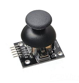
- The joystick measures the movement of its stick in different directions and transmits the position as values.
- The servo motor adjusts its position to a specific angle based on the input signal.
- Together, the joystick and servo allow for precise control of direction and position.
What Do I Need?
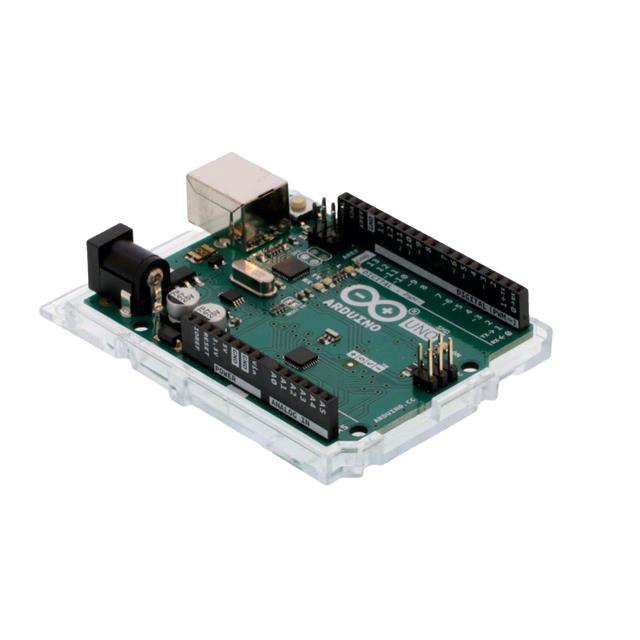
- Arduino (Uno R3 or a compatible clone)
- Joystick Module (QYF-860 or other compatible module)
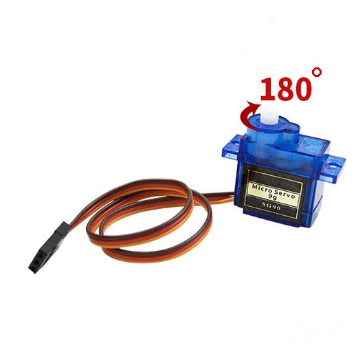
- Servo Motor 180°
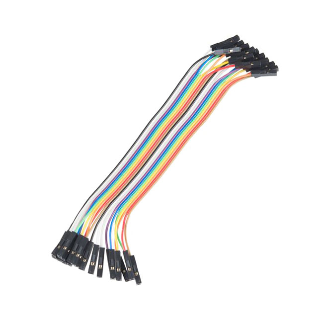
- Wires 6 pieces (For Breadboard)
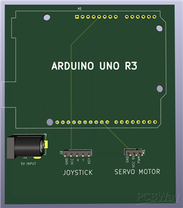
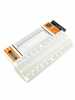
- PCB or Breadboard (Optional)
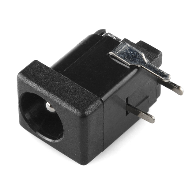
- DC Jack for power (Optional on PCB)
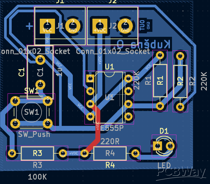
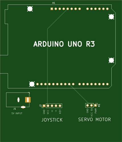
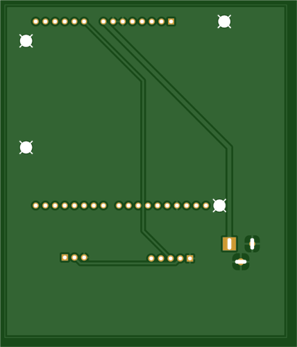
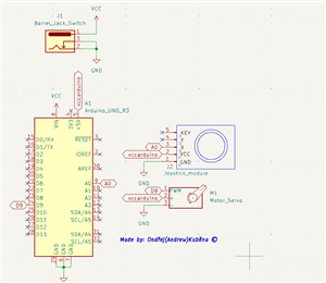
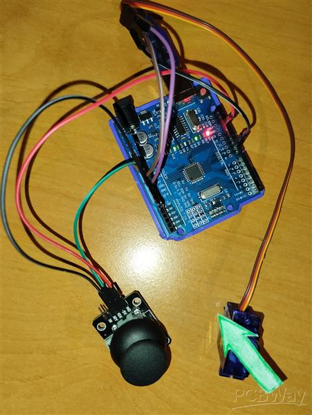
Image version:
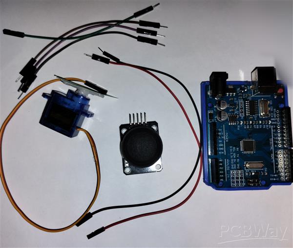
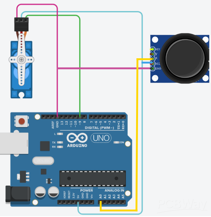
Wiring:
For the joystick module, we only use the X-axis (VRX).
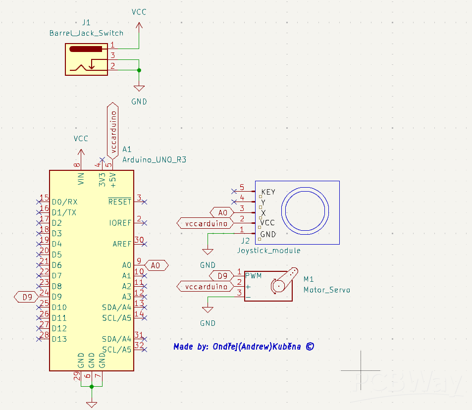
Schematic below, can also be found in uploaded images or GitHub.

Code & Setup
- In the Arduino IDE, enter the following (in attachments) code and upload it:
How Does This Code Work?
- The Servo library is included so we can control the servo easily.
- We create a Servo object (myServo) to communicate with the motor.
- The joystick is connected to analog pin A0, the servo to digital pin 9.
- The program reads the joystick position using analogRead().
- The map() function converts joystick readings (0–1023) to servo angles (0–180°).
- A tolerance is set so the servo doesn’t jitter when the joystick is centered.
- The servo moves smoothly to match the joystick’s movement.
Arduino Basics (For Beginners)
- Arduino Uno R3 is a small microcontroller board used to control electronics.
It is programmed in a language similar to C++.
- Pins are connection points where you can attach sensors, motors, LEDs, etc.
- Analog pins measure varying values (like joystick position).
- Digital pins turn things ON/OFF or send control pulses to motors.
- Programs for Arduino have two main parts:
setup() → runs once when powered on
loop() → runs continuously while powered
Real-World Applications
By combining a joystick and servo control, you can create:
Robotic Arms:
- Control each joint with a joystick for precise movement.
- Great for pick-and-place machines or DIY robots.
Pet Projects:
- Create moving toys for cats and dogs.
- Control treat dispensers or small interactive gadgets.
RC Cars & Vehicles:
- Use the joystick to control steering (servo) and throttle (motor driver).
- Perfect for remote-controlled boats, cars, or tanks.
Camera Gimbals
- Smoothly aim a camera by controlling servo motors with a joystick.
Expected Result
➡ Right Movement | Center Position | ⬅ Left Movement
When we move with the joystick to the left the servo will also turn left, when we move with the joystick to the right the servo will also move to the right, if we do nothing the servo will stay in a Center Position.
The servo will precisely follow your joystick’s position, allowing smooth and accurate control—ready to be expanded into larger robotics or automation projects.
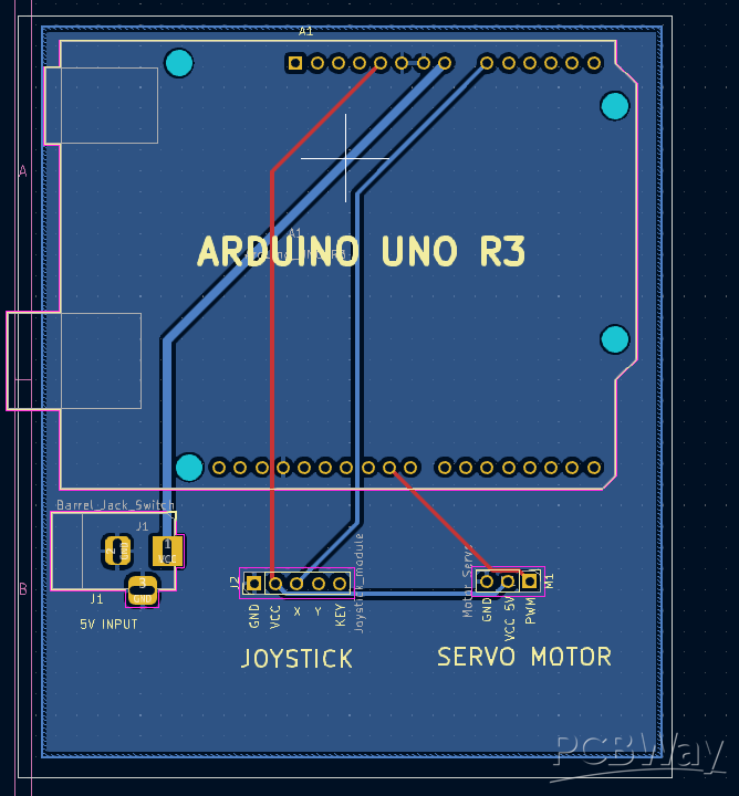
Gerbers, KiCad schematics, BOM, ZIP Files, Layouts all included here and on GitHub: Link: https://github.com/Ondrak-123/Arduino-basics
#include <Servo.h>

Servo myServo;               // Create Servo object
int joystickXPin = A0;       // Pin connected to joystick module (VRx)
int servoPin = 9;             // Pin connected to servo

int servoAngle = 90;          // Default servo angle (center position 90°)
int tolerance = 10;           // Tolerance for joystick center position (to prevent drift)

void setup() {
  myServo.attach(servoPin);   // Attach servo to pin
  myServo.write(servoAngle);  // Set default servo position to center (90°) since we have a 180° servo
  Serial.begin(9600);         // Initialize serial communication (for debugging)
}

void loop() {
  int joystickX = analogRead(joystickXPin);   // Read joystick value (VRx)

  // Map joystick values (0 - 1023) to servo range (0 - 180°)
  if (joystickX > 512 + tolerance || joystickX < 512 - tolerance) {
    servoAngle = map(joystickX, 0, 1023, 0, 180);
    myServo.write(servoAngle);  // Set servo according to joystick
  }

  // Small delay for stability
  delay(10);
}
Learn basics with Arduino! Controlling servo using joystick with Arduino Uno R3. For robotic arms, RC Cars, pets and gimbals.
*PCBWay community is a sharing platform. We are not responsible for any design issues and parameter issues (board thickness, surface finish, etc.) you choose.


- Comments(0)
- Likes(2)
More by Ondřej Kuběna
-
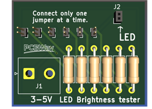 Choose the right brightness for your LEDs. LED RESISTANCE HELPER Tool
This board features 6 different resistance values so you can find the right brightness for your proj...
Choose the right brightness for your LEDs. LED RESISTANCE HELPER Tool
This board features 6 different resistance values so you can find the right brightness for your proj...
-
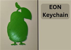 EON Keychain
, can be multicolor.No special settings or supports needed.Filament: PLANo rafts and no ...
EON Keychain
EON Keychain, can be multicolor.No special settings or supports needed.Filament: PLANo rafts and no ...
-
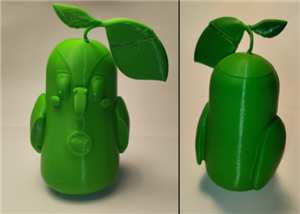 EON - Figure
, can be multicolor.Supports needed, organic support setting is best, you can use the au...
EON - Figure
EON - Figure, can be multicolor.Supports needed, organic support setting is best, you can use the au...
-
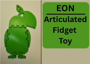 EON - Articulated fidget toy
EON-Articulated Fidget Toy, can be multicolor.No special setting or supports needed.Filament: PLANo ...
EON - Articulated fidget toy
EON-Articulated Fidget Toy, can be multicolor.No special setting or supports needed.Filament: PLANo ...
-
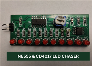 Led Chaser, Mostly SMD, using NE555 & CD4017
NE555 & CD4017 LED CHASER-The LEDS, RESISTORS AND INTEGRATED CIRCUITS are all SMD, therefore the...
Led Chaser, Mostly SMD, using NE555 & CD4017
NE555 & CD4017 LED CHASER-The LEDS, RESISTORS AND INTEGRATED CIRCUITS are all SMD, therefore the...
-
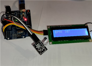 Arduino Heartbeat Monitor with HW-487 Pulse Sensor and 16×2 I²C LCD
This project is an Arduino Uno–based heartbeat monitor that uses the HW-487 pulse sensor to measure ...
Arduino Heartbeat Monitor with HW-487 Pulse Sensor and 16×2 I²C LCD
This project is an Arduino Uno–based heartbeat monitor that uses the HW-487 pulse sensor to measure ...
-
 Astable Multivibrator Using Transistors
This project is an Astable Multivibrator built with two BC546 NPN transistors, along with resistors ...
Astable Multivibrator Using Transistors
This project is an Astable Multivibrator built with two BC546 NPN transistors, along with resistors ...
-
 ZERO PCB 6*7cm - Perfboard
Please do not use BOM and the centroid file because they are irrevelant and not needed. (In the BOM ...
ZERO PCB 6*7cm - Perfboard
Please do not use BOM and the centroid file because they are irrevelant and not needed. (In the BOM ...
-
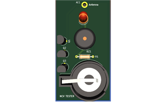 NCV Tester, Detect LIVE electronics
Warning / Safety Notice:This tester is for basic DIY and educational use only.It is not a profession...
NCV Tester, Detect LIVE electronics
Warning / Safety Notice:This tester is for basic DIY and educational use only.It is not a profession...
-
 ON/OFF Flip Flop Switch Using NE555
This project is an ON/OFF flip flop switch circuit built around the popular NE555 timer IC. It acts ...
ON/OFF Flip Flop Switch Using NE555
This project is an ON/OFF flip flop switch circuit built around the popular NE555 timer IC. It acts ...
-
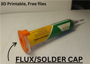 Solder Paste/Flux Syringe Cap
When solder paste or flux is left uncovered, it can dry out, harden, or become less effective. With ...
Solder Paste/Flux Syringe Cap
When solder paste or flux is left uncovered, it can dry out, harden, or become less effective. With ...
-
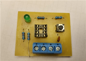
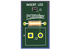 LED Tester
This project is a simple LED tester, designed to quickly check LEDs of different colors, sizes, and ...
LED Tester
This project is a simple LED tester, designed to quickly check LEDs of different colors, sizes, and ...
-
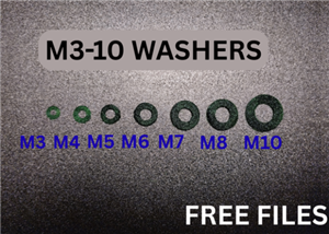 M3-M10 WASHERS
Overview:M3-M10 3D printed washers fit bolts or screws sized M3 to M10. They can be printed in a var...
M3-M10 WASHERS
Overview:M3-M10 3D printed washers fit bolts or screws sized M3 to M10. They can be printed in a var...
-
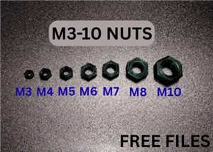 M3-M10 NUTS
Overview: M3-M10 3D printed nuts are customizable fasteners that fit bolts or screws sized M3 to M10...
M3-M10 NUTS
Overview: M3-M10 3D printed nuts are customizable fasteners that fit bolts or screws sized M3 to M10...
-
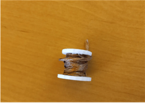 WICK, Solder Wire, Tin spool holder
This project is a 3D printed coil holder designed for organizing wires, soldering tin, and other spo...
WICK, Solder Wire, Tin spool holder
This project is a 3D printed coil holder designed for organizing wires, soldering tin, and other spo...
-
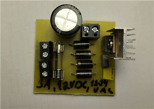 Power Supply for Audio Amplifier
INPUT 16-18VACOUTPUT1 12VDCOUTPUT2 24VDCThis project is a dedicated power supply unit designed for ...
Power Supply for Audio Amplifier
INPUT 16-18VACOUTPUT1 12VDCOUTPUT2 24VDCThis project is a dedicated power supply unit designed for ...
-
 Fume Extractor with 3D Printed Case, Carbon Filter and 70mm (or any) Fan
This project is a DIY fume extractor designed to keep your soldering area safe and clean.Features:3D...
Fume Extractor with 3D Printed Case, Carbon Filter and 70mm (or any) Fan
This project is a DIY fume extractor designed to keep your soldering area safe and clean.Features:3D...
-
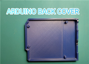 Arduino UNO R3 Back Cover
Protect and organize your Arduino Uno R3 with this precision-designed back cover. It shields the boa...
Arduino UNO R3 Back Cover
Protect and organize your Arduino Uno R3 with this precision-designed back cover. It shields the boa...
-
-
-
-
Tester for Touch Screen Digitizer without using microcontroller
319 2 2 -
Audio reactive glow LED wristband/bracelet with NFC / RFID-Tags
304 0 1 -
-
-


