


|
|
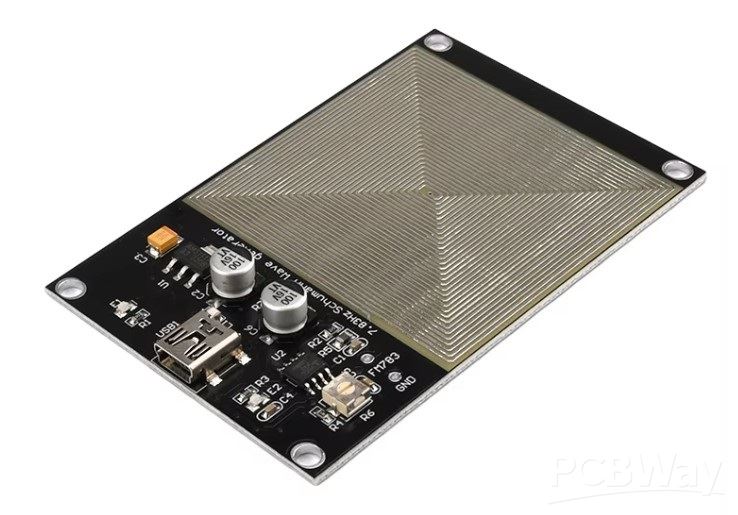
7.83Hz Module |
x 1 | |
|
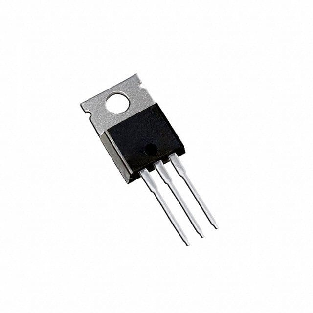
IRF3205ZPBFInfineon Technologies
|
x 1 | |
|
|
1N4007 |
x 1 | |
|
|
Resistor 100 ohm |
x 1 | |
|
|
coil |
x 1 |

|
Soldering iron (generic) |
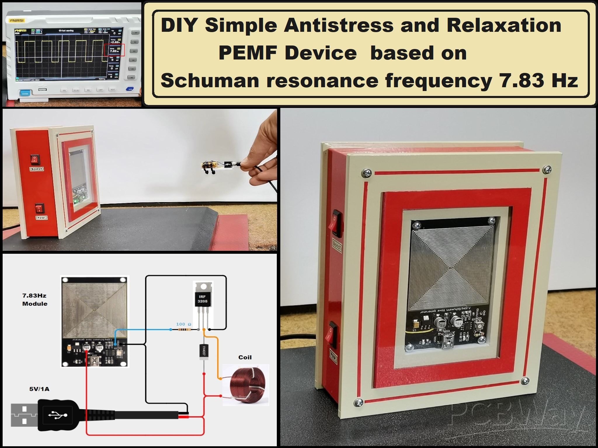
DIY Simple Antistress and Relaxation PEMF Device based on Schumannn resonance frequency 7.83 Hz
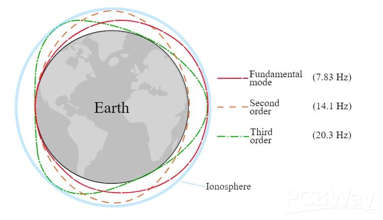
Schumann resonances are global electromagnetic resonances, generated by lightning discharges in the space formed by the Earth's surface and the ionosphere. The primary frequency of Schumann resonance is around 7.83 Hz and has several harmonic frequencies, including 14.07 Hz, 20.25 Hz, 26.41 Hz, and 32.45 Hz.
Multiple studies suggest that the Schumann frequency of 7.83 Hz positively affects human health and well-being. It has been linked to improved cognitive functions, reduced stress , enhanced immune function, sleep function, and much more. For example the Alpha brain wave activities [between 7 and 14 Hz] are a state wherein a person is relaxed. This frequency is also often used in PEMF therapy devices for general improvement of the body's condition, reducing the effects of stress and improving sleep.
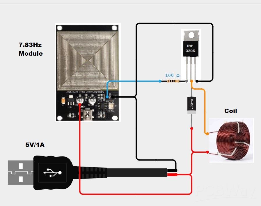
This time I will present you an exclusively simple way to make such a PEMF device using a cheap Schumann frequency generator module, and an amplifier of generated signal.
Otherwise, this module costs only a few dollars, and according to the seller's claim, it should radiate an electromagnetic field with this frequency. A so-called pancake coil is made on the PCB, which is supposed to be the source of the radiation.
This project is sponsored by PCBWay. This year, PCBWay organizes the Seventh Project Design Contest where, in addition to Electronic and Mechanical Project, also has been added a new category: STM32 Project. For the best selected projects are provided rich prizes in cash, coupons and special gifts. Submit your project for participation in this Contest from 2nd, Sep, 2024 to 19th, Jan, 2025. For more details and instructions visit the given page. Let PCBway always be your first choice.

Now let's test the function of this module to examine the shape and strength of the signal, and the frequency at which it oscillates. For this purpose, I will use an oscilloscope, as well as an electromagnetic radiation detector, which is actually a coil from a small electromagnetic relay that is connected to the microphone input of the PC.
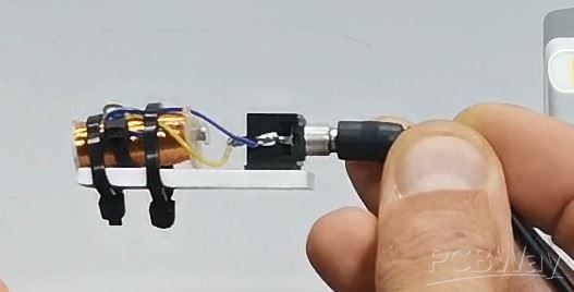
Under the action of the variable magnetic field, a current is induced in the coil, which is then amplified and then manifests as clicks on the PC speaker.
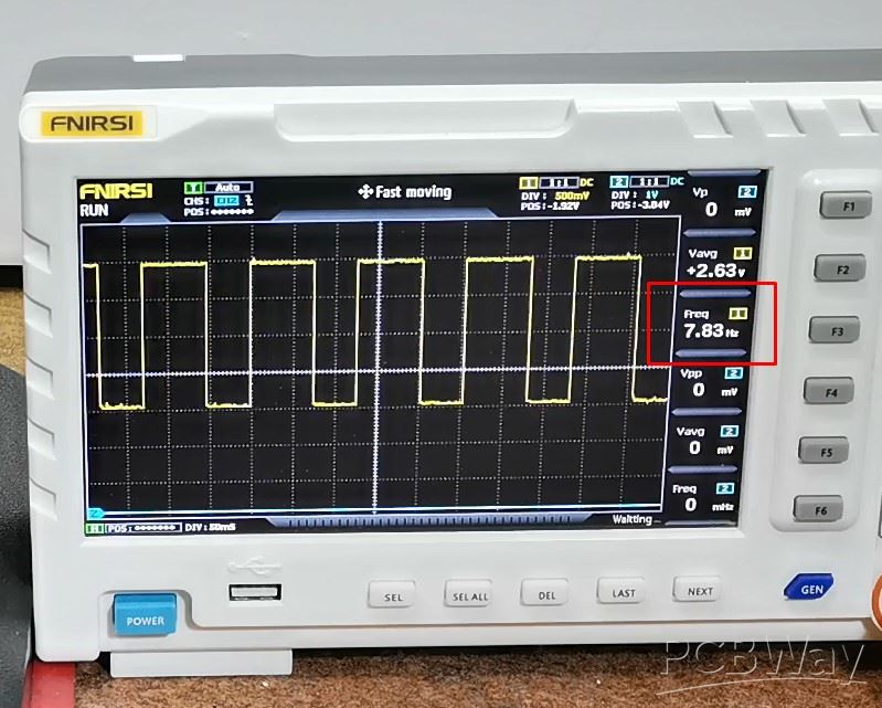
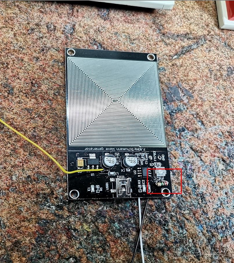
First let's check the oscillation frequency: Two points are the output of the oscillator. As we see the frequency is 6.5Hz. On the board there is a small trimmer potentiometer with which we can precisely set the desired frequency. Unfortunately, on my particular module, the maximum frequency that could be set was about 7.5 Hz. To correct that, in place of small 360Kohm resistor, I connected a 2M resistor in parallel. After this modification I can set exactly the requested frequency of 7.83Hz.
This is the only sample I own, so I hope your sample can be tuned to the correct frequency without any modifications. Here is what my modified module looks like
Now let's check if this little PCB coil emits EMF rays at all. The module is made on the basis of a timer IC - 555 and the output of the circuit is directly connected to the PCB coil. This means that a current of several tens of milliamps flows through the coil, which is not enough for practical use. The distance at which the field is detected is extremely small and amounts to about 1cm. This is a very weak field and can possibly be used placed directly on some part of the body. My idea is to make a device that would be connected somewhere in the living room or bedroom and would radiate throughout the room and would have the function of a relaxer or sleep enhancer.
For that purpose, I made a device that will amplify this rectangular pulsating signal with a powerful mosfet transistor, and I will bring it to a suitable coil made of insulated copper wire which will be a source of strong electromagnetic radiation.
Let's take a look at what's inside the box:
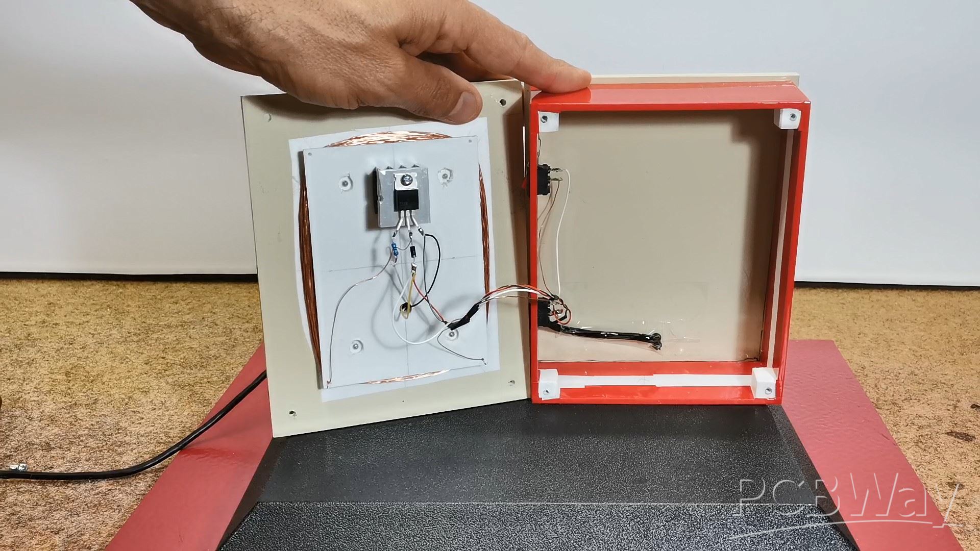
The mosfet is mounted on an aluminum heatsink and powered by an external 12V /2A source. I also used a 7805 voltage regulator to power the module. Making the coil is not critical, but some general conditions must be observed. In this particular case, the coil consists of lacquered wire with a diameter of 0.2 mm and a total length of 12 m, while the ohmic resistance of the coil is 8 Ohms. As a general recommendation, the ohmic resistance of the coil should not be less than 2 ohms or more than 10 ohms, and the copper wire should have a cross-sectional area between 0.2 and 0.5 mm2.
Now let's see how this device works in reality. When the voltage is switched on, one LED lights up constantly, and the other flashes with a frequency of 7.86 Hz. This is a basic sign that the device is working. So that you can see the difference between the original module and the device after the modification I have installed this BOOST switch.
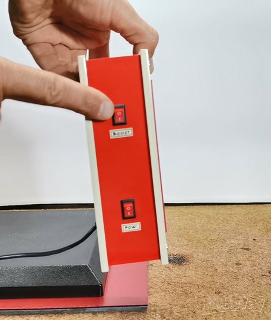
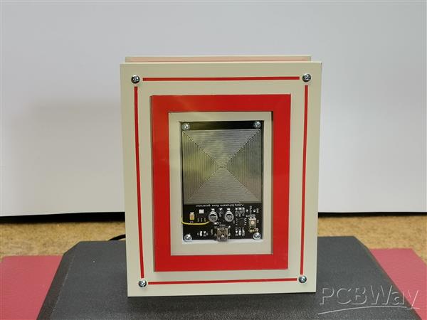
When it is in position 0, only the original module works, and in position 1, is turns on the mosfet amplifier with a new coil . Next, let's check the strength of the electromagnetic field with the previously described detector. As you can see now the detector reacts at a distance greater than 50cm. Taking into account the fact that the field strength decreases proportionally to the square of the distance from the source, this means that now the EMF radiation is tens of times stronger than at the module itself. Now the strength of the magnetic field has a value of about 10 Gauss. For a better visual and so-called Placebo effect, I mounted the module on the front of the box.
And finally a short conclusion. In this video I described a very simple way to turn this module into a really functional and cheap PEMF device that is usually sold at a very high price.
I am not a medical expert and I cannot discuss the effect of the device. If you are considering usе it for health-related purposes, it is crucial to consult a qualified healthcare professional to ensure safety and efficacy. This video only explains the technical aspect of this device (how to build it).

DIY Simple Antistress and Relaxation PEMF Device based on Schumannn resonance frequency 7.83 Hz


Raspberry Pi 5 7 Inch Touch Screen IPS 1024x600 HD LCD HDMI-compatible Display for RPI 4B 3B+ OPI 5 AIDA64 PC Secondary Screen(Without Speaker)
BUY NOW


- Comments(0)
- Likes(0)
More by Mirko Pavleski
-
 Arduino 3D Printed self Balancing Cube
Self-balancing devices are electronic devices that use sensors and motors to keep themselves balanc...
Arduino 3D Printed self Balancing Cube
Self-balancing devices are electronic devices that use sensors and motors to keep themselves balanc...
-
 DIY Miniature X-Ray Machine using a TV Vacuum Tube DY86
An X-ray machine (or radiograph) is a quick, painless medical test that produces images of the struc...
DIY Miniature X-Ray Machine using a TV Vacuum Tube DY86
An X-ray machine (or radiograph) is a quick, painless medical test that produces images of the struc...
-
 Simple SDR Receiver Using 2x NE612 - Dual Conversion, Superheterodyne (0.1–30 MHz)
SDR (Software Defined Radio) is a radio system in which most of the functions of a classic radio (f...
Simple SDR Receiver Using 2x NE612 - Dual Conversion, Superheterodyne (0.1–30 MHz)
SDR (Software Defined Radio) is a radio system in which most of the functions of a classic radio (f...
-
 DIY Vintage TV VU Meter with peak indicators
Some time ago in one of my projects I presented you a way to turn a black and white old mini TV int...
DIY Vintage TV VU Meter with peak indicators
Some time ago in one of my projects I presented you a way to turn a black and white old mini TV int...
-
 DIY Tesla Coil based Plasma Rife Machine
In several of my previous videos, I presented you with different ways to make a Rife Machine, from ...
DIY Tesla Coil based Plasma Rife Machine
In several of my previous videos, I presented you with different ways to make a Rife Machine, from ...
-
 ESP32 Analog VU Meter – Smooth Needle, Real Audio Response (DIY Build)
In several of my previous videos I have shown you how to make analog VU meters emulated on differen...
ESP32 Analog VU Meter – Smooth Needle, Real Audio Response (DIY Build)
In several of my previous videos I have shown you how to make analog VU meters emulated on differen...
-
 The Ultimate Smartphone VFO ESP32 & Si5351 Wireless Control
Variable frequency oscillators (VFOs) are commonly used in radio transmitters and receivers, especi...
The Ultimate Smartphone VFO ESP32 & Si5351 Wireless Control
Variable frequency oscillators (VFOs) are commonly used in radio transmitters and receivers, especi...
-
 DIY Shortwave Propagation Monitor - Measure Ionosphere Conditions
Shortwave Propagation is the way radio waves in the 3 to 30 MHz range travel from point A to point ...
DIY Shortwave Propagation Monitor - Measure Ionosphere Conditions
Shortwave Propagation is the way radio waves in the 3 to 30 MHz range travel from point A to point ...
-
 Professional grade Smart Lock with ESP32, BLE and Android App Control
An electronic codelock is a security device that grants access using a numerical sequence—a PIN cod...
Professional grade Smart Lock with ESP32, BLE and Android App Control
An electronic codelock is a security device that grants access using a numerical sequence—a PIN cod...
-
 Building a 3-Input Stereo ECC83 (12AX7) Tube Preamp
Some time ago I presented you a project for a 3W stereo tube amplifier with a GU32 output vacuum t...
Building a 3-Input Stereo ECC83 (12AX7) Tube Preamp
Some time ago I presented you a project for a 3W stereo tube amplifier with a GU32 output vacuum t...
-
 ESP32 Weather Dashboard with Satellite Maps and 16-day Weather Forecast
As you can see from my previous videos, besides Electronics, my fields of experimentation and proje...
ESP32 Weather Dashboard with Satellite Maps and 16-day Weather Forecast
As you can see from my previous videos, besides Electronics, my fields of experimentation and proje...
-
 Retro Analog VU Meter on Round dispalys (ESP32 and GC9A01)
Recently, in one of my previous videos I presented you a Retro VU Meter project on round displays ...
Retro Analog VU Meter on Round dispalys (ESP32 and GC9A01)
Recently, in one of my previous videos I presented you a Retro VU Meter project on round displays ...
-
 Ultimate 2-Player Reaction Timer with WS2812B LED Strips & Arduino
Arcade reaction game is a genre of play designed to test a player's physical response time and hand...
Ultimate 2-Player Reaction Timer with WS2812B LED Strips & Arduino
Arcade reaction game is a genre of play designed to test a player's physical response time and hand...
-
 Building a Vintage Tube-Style Internet Radio with Raspberry Pi & Rotary Encoder
Internet radio (also known as web radio or net radio) is a digital audio service transmitted via th...
Building a Vintage Tube-Style Internet Radio with Raspberry Pi & Rotary Encoder
Internet radio (also known as web radio or net radio) is a digital audio service transmitted via th...
-
 DIY Smart Code Lock with CrowPanel 1.28 ESP32 Rotary Display
A code lock is a keyless security device—either mechanical or electronic—that restricts access to d...
DIY Smart Code Lock with CrowPanel 1.28 ESP32 Rotary Display
A code lock is a keyless security device—either mechanical or electronic—that restricts access to d...
-
 SDR Panadapter for Vintage Tube Radios – Step-by-Step Tutorial
A radio panadapter (or panoramic adapter) is a device or software tool used in amateur radio and ot...
SDR Panadapter for Vintage Tube Radios – Step-by-Step Tutorial
A radio panadapter (or panoramic adapter) is a device or software tool used in amateur radio and ot...
-
 Oscilloscope Clock Simulation on a Round ESP32 Display
An oscilloscope clock is a circuit that turns an old analog oscilloscope into a stylish, retro-them...
Oscilloscope Clock Simulation on a Round ESP32 Display
An oscilloscope clock is a circuit that turns an old analog oscilloscope into a stylish, retro-them...
-
 DIY Simple GU32 Tube Stereo Amplifier (2x3W on 12VDC)
Vacuum tube amplifiers are often favored for their smooth harmonic distortion, especially in the low...
DIY Simple GU32 Tube Stereo Amplifier (2x3W on 12VDC)
Vacuum tube amplifiers are often favored for their smooth harmonic distortion, especially in the low...
-
Programmable Mist Maker - XIAO / QT PY Extension
171 0 0 -
RadioHAT - Raspberry Pi radio development platform
180 0 1 -
-
-
-
-
ARPS-2 – Arduino-Compatible Robot Project Shield for Arduino UNO
2766 0 5 -
A Compact Charging Breakout Board For Waveshare ESP32-C3
3273 3 8 -
AI-driven LoRa & LLM-enabled Kiosk & Food Delivery System
3528 2 2


