


|
|
STM32F103C8 -Blue Pill |
x 1 | |
|
|
TM1637 - 4 Digit 7 Segment Display |
x 1 | |
|
|
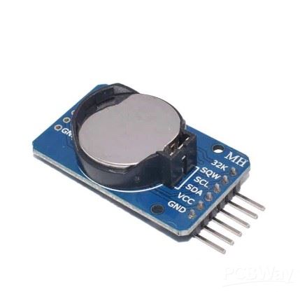
DS3231 Realtime clock midule |
x 1 | |
|
|
Pushbutton |
x 4 | |
|
|
Buzzer |
x 1 | |
|
|
Resistor 10k ohm |
x 4 |

|
Soldering Iron Kit |
|

|
arduino IDEArduino
|
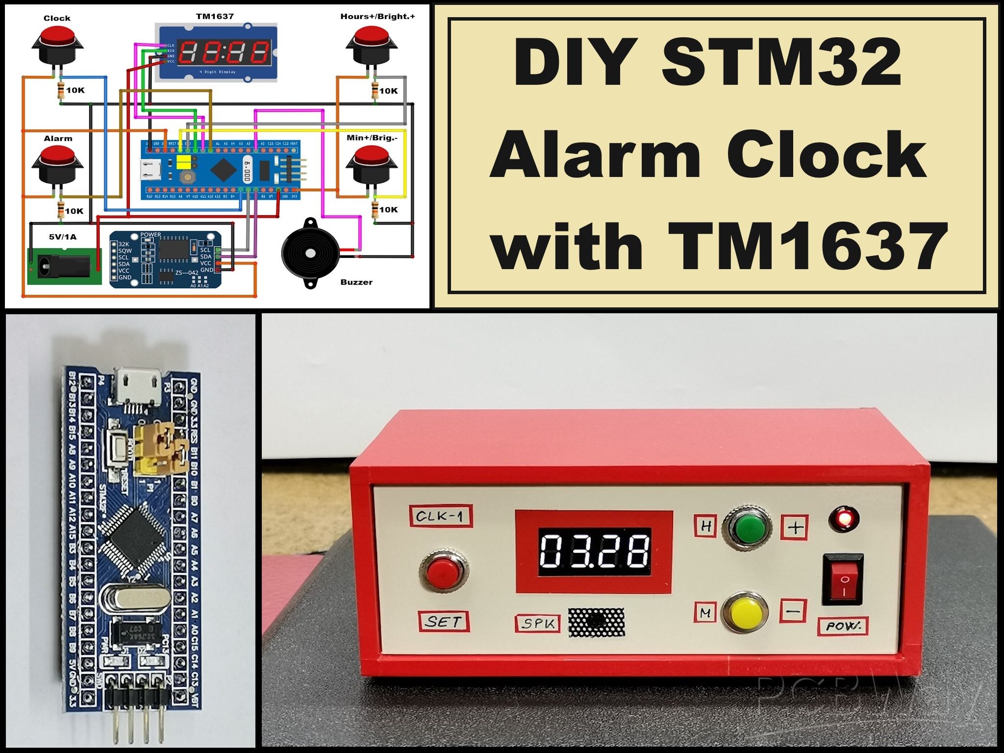
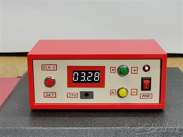
DIY STM32 Alarm Clock with 7-Segment Display (Using Arduino IDE)
This time I will present you a classic 7 segment display alarm clock which will represent another one from my series of DIY unusual and ordinary clocks which you can watch on my playlist. In this case, it is characteristic that is used the STM32 microcontroller board known as "Blue Pill".
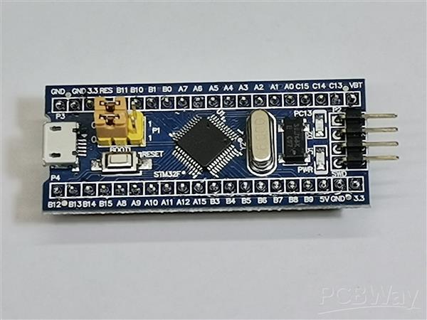
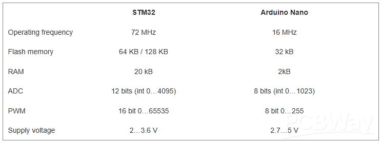
It is a popular and inexpensive development board based on the STM32F103C8T6 microcontroller from STMicroelectronics. The ARM Cortex-M3 core offers much more processing power and peripherals compared to typical 8-bit microcontrollers like those found in the Arduino.
Its price is also significantly lower than many other development boards with similar capabilities. The code is taken from the RCL-Radio blog where you can also find detailed instructions.
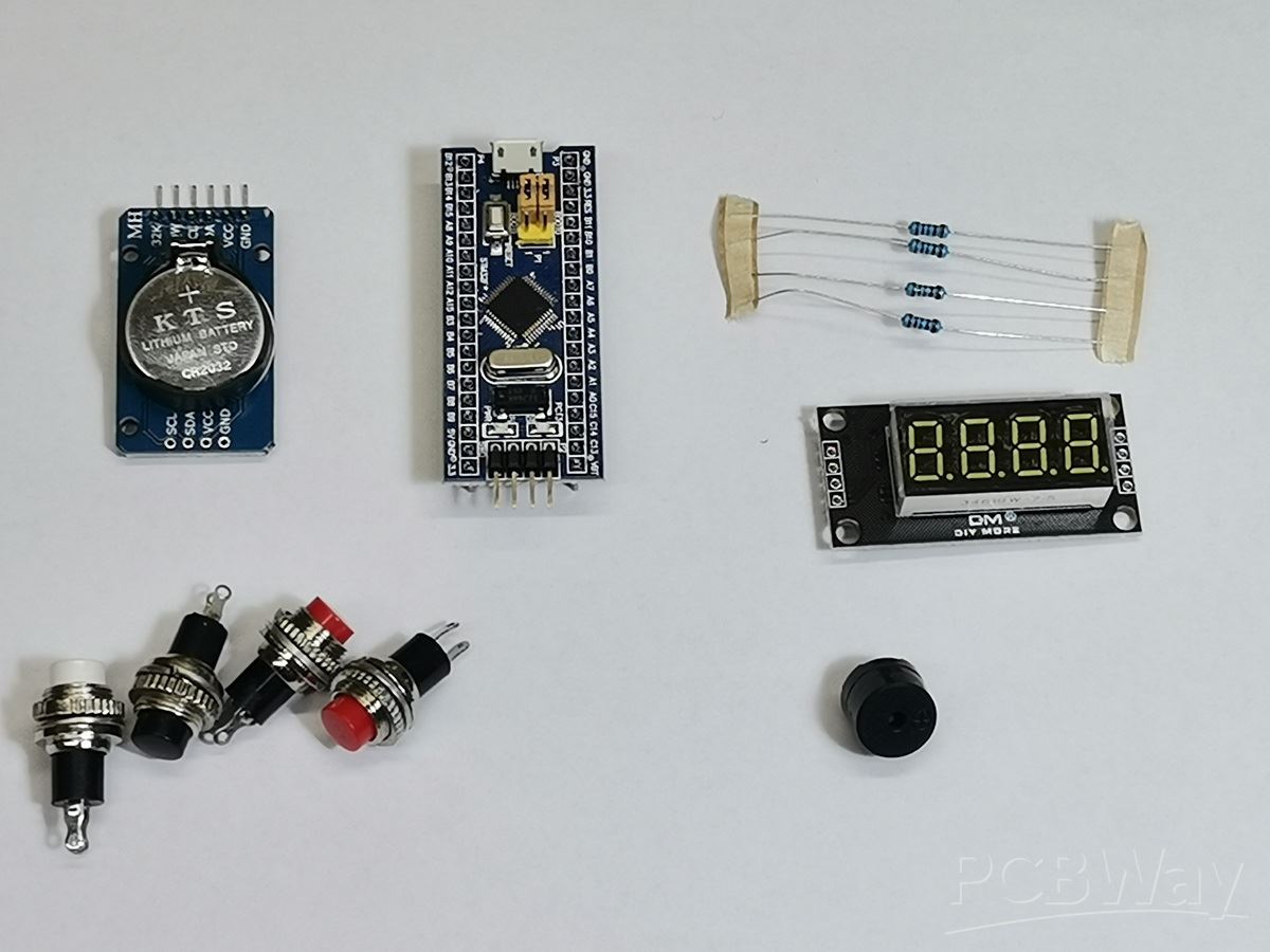
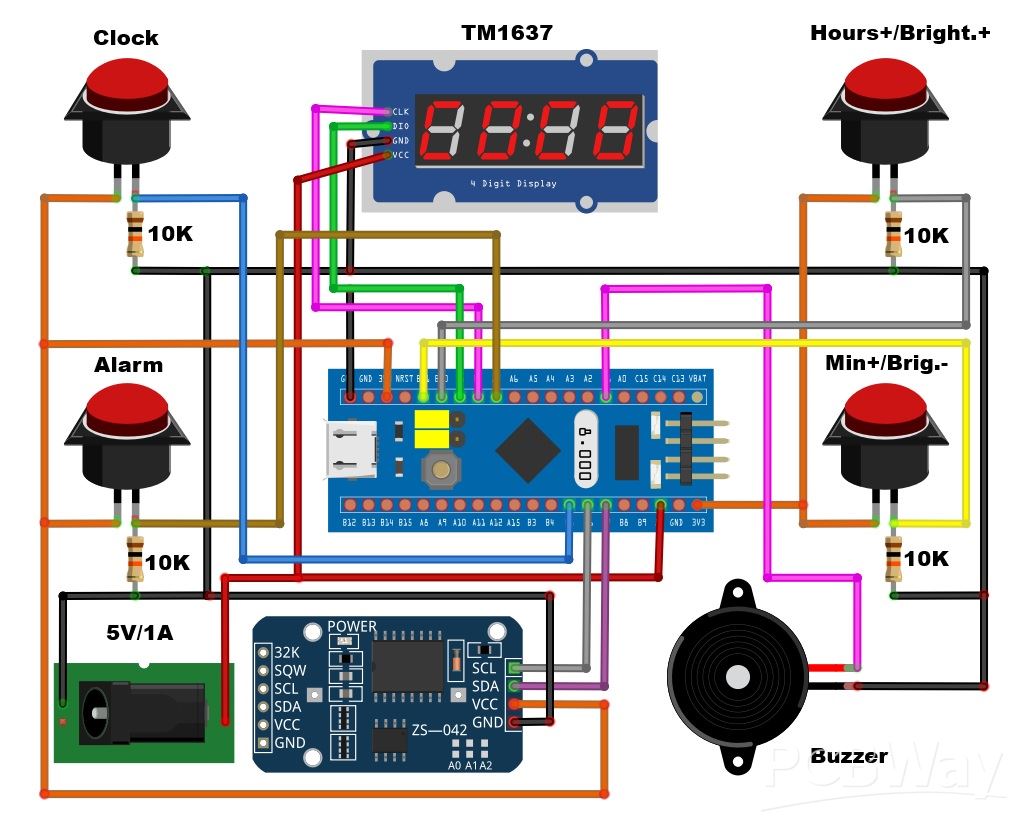
The device is extremely simple to build and the total cost does not exceed 5-6 dollars. It consists of several components:
- STM32 Microcontroller board
- TM1637 4-digit 7-segment display module
- DS3231 Realtime clock midule
- 4 Buttons
- and small Buzzer
First, let me explain how to install the code on the Blue Pill board.
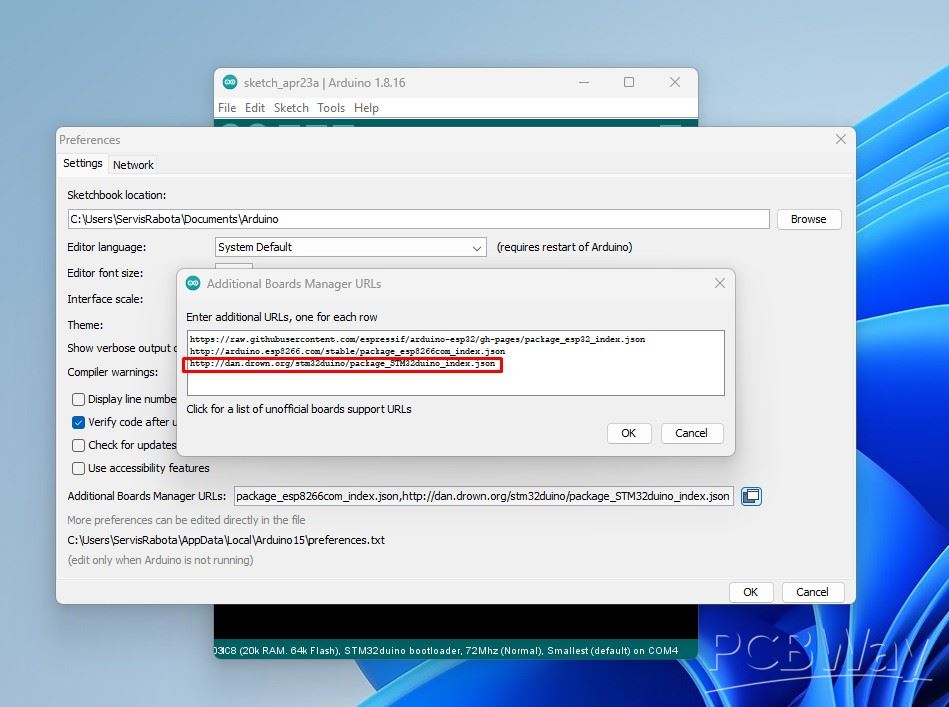
To start programming in the Arduino IDE, you need to add the STM32 board
- File > Settings > Additional links for board manager
Add line: http://dan.drown.org/stm32duino/package_STM32duino_index.json
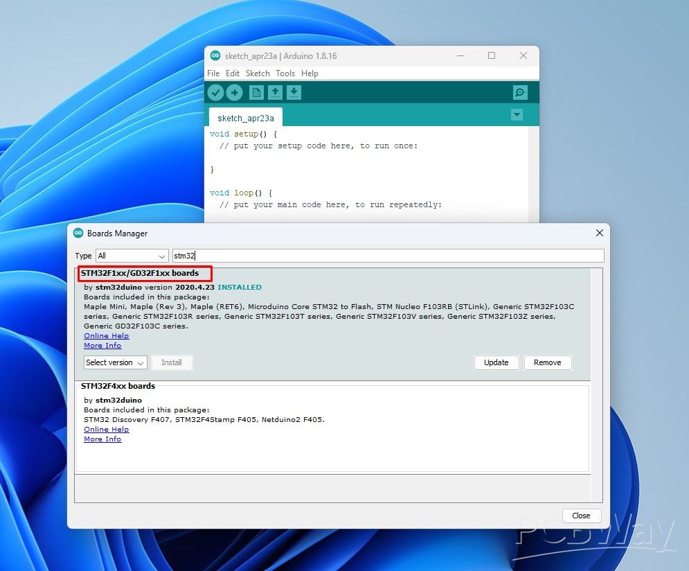
- Then, Open the board manager
Tools > Boards > Board Manager and type STM32 -> install
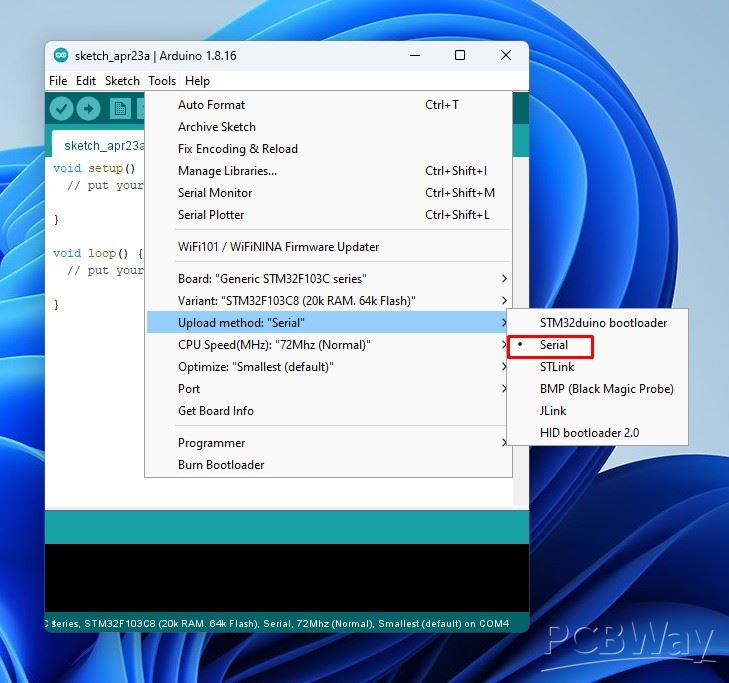
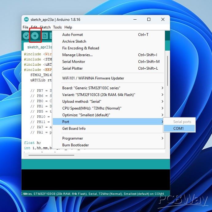
- Now we select "GenericSTM32 F103C series", and in the Upload method section, select Serial
- The simplest way to upload the code is to use a small USB to COM adapter and connect it as shown in the diagram.
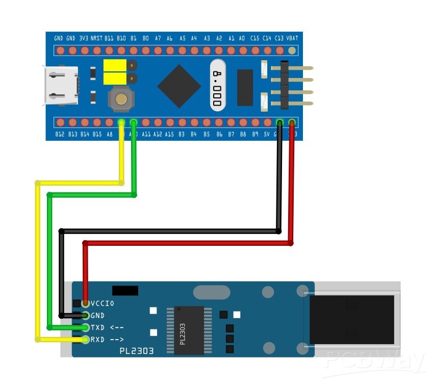
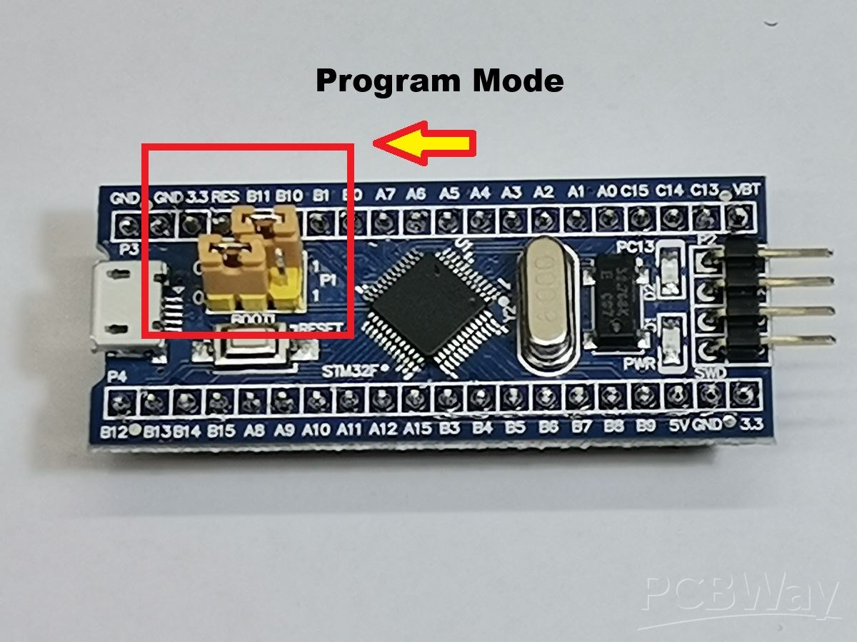
- First we need to set the jumper on the STM32 to "Program mode" as shown in the image.
- Then, We select the COM port that corresponds to the USB to COM adapter and press upload.
When the upload is complete, we return the jumper to its original position, and remove the USB to COM adapter from the PC.
Now the code has been successfully uploaded and we can mount all the components.
In the style of a classic alarm clock, use a real-time clock module with a built-in battery to store the set time when not connected to power.
Thanks to the four buttons, setting is extremely simple. To adjust the time and alarm time, you need to press and hold the time set or alarm button and use the hours++ and minutes++ buttons to set the desired time. Тo set the seconds accurately, set the minutes 1 minute more; when changing the minutes, press the "Time adjustment" button to reset the seconds.
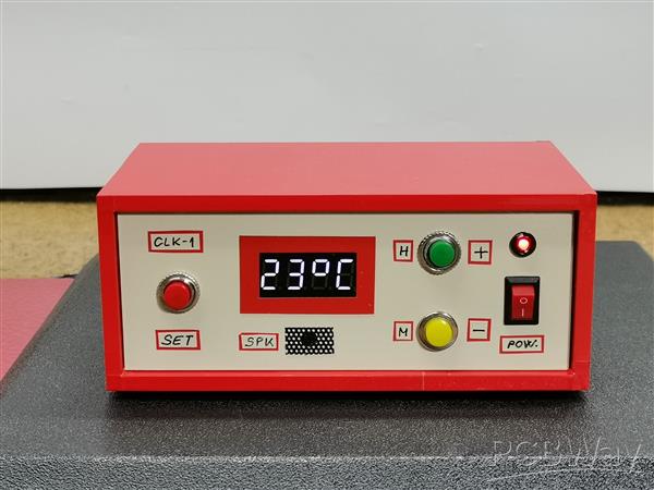
You can also adjust the display brightness by simply pressing the h+ and m+ buttons. The DS3231 real time clock contains a temperature sensor, and the temperature sensor readings are displayed on the display every 10 seconds.
When the alarm is activated, a sound signal is emitted from the piezo emitter for one minute, and if we press any of the buttons in the meantime, the sound stops.
Finally, a short conclusion. With its simple design, low cost, and easy setup, this STM32 alarm clock is a perfect DIY project for beginners and electronics enthusiasts alike.
#include <Wire.h>
#include <STM32_TM1637.h> // http://rcl-radio.ru/wp-content/uploads/2020/02/STM32_TM1637_V1_3.zip
#include <uRTCLib.h> // https://github.com/Naguissa/uRTCLib.git
#include <EEPROM.h> // http://rcl-radio.ru/wp-content/uploads/2019/12/Arduino_STM32-master.zip
   STM32_TM1637 tm ( PB0,PB1 ) ; // CLK, DIO
   uRTCLib rtc ( 0x68 ) ;

   // PB7 = SDA DS1307 (DS3231)
   // PB6 = SCL DS1307 (DS3231)
   // PB0 = CLK TM1637
   // PB1 = DIO TM1637
   // PB5 = time correction
   // PB10 = hours++, brightness++
   // PB11 = minutes++, brightness--
   // PA7 = alarm correction
   // PA1 = piezo buzzer

float h;
int i,hh,mm,brig,al_hh,al_mm;
byte w,alarm,w1;

void setup ( ) {
   Wire. begin ( ) ;
  EEPROM.init(0x801F000, 0x801F800, 0x400); // 1024 byte
   brig = EEPROM. read ( 10 ) ;al_hh = EEPROM. read ( 11 ) ;al_mm = EEPROM. read ( 12 ) ;
   // rtc.set(30, 37, 23, 2, 17, 12, 19);
  // RTCLib::set(byte second, byte minute, byte hour, byte dayOfWeek, byte dayOfMonth, byte month, byte year)
  pinMode ( PB5,INPUT ) ; pinMode ( PB10,INPUT ) ; pinMode ( PB11,INPUT ) ; pinMode ( PA7,INPUT ) ;
  pinMode ( PA1, PWM ) ;
   if ( brig > 4 ) { brig= 4 ; } tm. brig ( brig ) ;
 }

void loop ( ) { alarm= 0 ;
 //////////////////////////////////// time output
  if ( digitalRead ( PB5 ) ==LOW && alarm== 0 && digitalRead ( PA7 ) ==LOW ) {
   hh=rtc. hour ( ) ;mm=rtc. minute ( ) ;
   rtc. refresh ( ) ; // time poll
   h = rtc. hour ( ) * 100 + rtc. minute ( ) ;tm. print_time ( h, 0 ) ;delay ( 500 ) ;
   tm. print_time ( h, 1 ) ;delay ( 500 ) ;i++;
 //if(i==10){i=0;tm.print_float(rtc.temp()/100,0 ,0b1111000,0,0,0);delay(2000);}// DS3231 temperature output (t 27)
if ( i== 10 ) { i= 0 ;tm. print_float ( rtc. temp ( ) , 0 , 0 , 0 , 0b01100011 , 0b00111001 ) ; delay ( 2000 ) ; } // output temperature DS3231 (27*C)
  }
///////////////////////////////////////// time correction - hours and minutes
  if ( digitalRead ( PB5 ) ==HIGH && digitalRead ( PB10 ) ==HIGH ) { w= 1 ;hh++; if ( hh > 23 ) { hh= 0 ; } delay ( 300 ) ;tm. print_time ( hh * 100 +mm, 1 ) ; }
  if ( digitalRead ( PB5 ) ==HIGH && digitalRead ( PB11 ) ==HIGH ) { w= 1 ;mm++; if ( mm > 59 ) { mm= 0 ; } delay ( 300 ) ;tm. print_time ( hh * 100 + mm, 1 ) ; }
  if ( digitalRead ( PB5 ) ==HIGH && digitalRead ( PB10 ) ==LOW && digitalRead ( PB11 ) ==LOW ) { rtc. set ( 0 , mm , hh , - 1 , - 1 , - 1 , - 1 ) ; }
  if ( w== 1 ) { w= 0;rtc. set ( 0 , mm , hh , - 1 , - 1 , - 1 , - 1 ) ; }
////////////////////////////////// indicator brightness
  if ( digitalRead ( PB10 ) ==HIGH && digitalRead ( PA7 ) ==LOW && digitalRead ( PB5 ) ==LOW ) { brig++; if ( brig > 4 ) { brig= 4 ; } tm. brig ( brig ) ;EEPROM. update ( 10 , brig ) ; }
  if ( digitalRead ( PB11 ) ==HIGH && digitalRead ( PA7 ) ==LOW && digitalRead ( PB5 ) ==LOW ) { brig--; if ( brig < 0 ) { brig= 0 ; } tm. brig ( brig ) ;EEPROM. update ( 10 , brig ) ; }
/////////////////////////////////// alarm clock
  if ( digitalRead ( PA7 ) ==HIGH && digitalRead ( PB10 ) ==HIGH ) { w1= 0 ;al_hh++; if ( al_hh > 23 ) { al_hh= 0 ; } delay ( 300 ) ;EEPROM. update ( 11 , al_hh ) ; }
  if ( digitalRead ( PA7 ) ==HIGH && digitalRead ( PB11 ) ==HIGH ) { w1= 0 ;al_mm++; if ( al_mm > 59 ) { al_mm= 0 ; } delay (300 ) ;EEPROM. update ( 12 , al_mm ) ; }
  if ( digitalRead ( PA7 ) ==HIGH ) { tm. print_time ( al_hh * 100 + al_mm, 1 ) ; }

  if ( hh * 100 +mm==al_hh * 100 +al_mm && w1== 0 ) { alarm= 1 ; } else { alarm= 0 ; }
  if ( alarm== 1 && ( digitalRead ( PA7 ) ==HIGH || digitalRead ( PB5 ) ==HIGH || digitalRead ( PB10 ) ==HIGH || digitalRead ( PB11 ) ==HIGH ) ) { alarm= 0 ;w1= 1 ; }
  if ( alarm== 1 ) { pwmWrite ( PA1, 35000 ) ;delay ( 200 ) ; pwmWrite ( PA1, 0 ) ;delay ( 100 ) ; } else { pwmWrite ( PA1, 0 ) ; }
  } // loop
DIY STM32 Alarm Clock with 7-Segment Display (Using Arduino IDE)


Raspberry Pi 5 7 Inch Touch Screen IPS 1024x600 HD LCD HDMI-compatible Display for RPI 4B 3B+ OPI 5 AIDA64 PC Secondary Screen(Without Speaker)
BUY NOW


- Comments(0)
- Likes(0)
More by Mirko Pavleski
-
 Arduino 3D Printed self Balancing Cube
Self-balancing devices are electronic devices that use sensors and motors to keep themselves balanc...
Arduino 3D Printed self Balancing Cube
Self-balancing devices are electronic devices that use sensors and motors to keep themselves balanc...
-
 Elecrow All-in-One Arduino Starter Kit Review - 20 Projects & 16 Modules
This time I will describe a simple and practical way to enter the world of microcontrollers, specif...
Elecrow All-in-One Arduino Starter Kit Review - 20 Projects & 16 Modules
This time I will describe a simple and practical way to enter the world of microcontrollers, specif...
-
 ESP32-C3 Color Detector with TCS34725, Real-Time RGB Detection & Web Interface
Color detection is a fundamental task in many embedded systems – from industrial sorting machines t...
ESP32-C3 Color Detector with TCS34725, Real-Time RGB Detection & Web Interface
Color detection is a fundamental task in many embedded systems – from industrial sorting machines t...
-
 DIY ESP32 Telegram Flood Protection System - Smart Home Automation
Recently I had an unpleasant experience in my home, specifically my ground floor was flooded as a r...
DIY ESP32 Telegram Flood Protection System - Smart Home Automation
Recently I had an unpleasant experience in my home, specifically my ground floor was flooded as a r...
-
 Real-Time Air Traffic Radar using ESP32 + ADS-B Data
ADS-B, which stands for Automatic Dependent Surveillance-Broadcast, is the modern standard for trac...
Real-Time Air Traffic Radar using ESP32 + ADS-B Data
ADS-B, which stands for Automatic Dependent Surveillance-Broadcast, is the modern standard for trac...
-
 DIY Green Laser Night Sky Object Finder - Find Stars & Galaxies Instantly with great accuracy
As an amateur astronomer, especially at the beginning, the most difficult part of observing the nig...
DIY Green Laser Night Sky Object Finder - Find Stars & Galaxies Instantly with great accuracy
As an amateur astronomer, especially at the beginning, the most difficult part of observing the nig...
-
 DIY Avionics Simulator with ESP32 - Artificial Horizon, Compass & Altimeter
The inspiration for this project comes from classical aircraft cockpit instruments used for navigat...
DIY Avionics Simulator with ESP32 - Artificial Horizon, Compass & Altimeter
The inspiration for this project comes from classical aircraft cockpit instruments used for navigat...
-
 DIY Miniature X-Ray Machine using a TV Vacuum Tube DY86
An X-ray machine (or radiograph) is a quick, painless medical test that produces images of the struc...
DIY Miniature X-Ray Machine using a TV Vacuum Tube DY86
An X-ray machine (or radiograph) is a quick, painless medical test that produces images of the struc...
-
 Simple SDR Receiver Using 2x NE612 - Dual Conversion, Superheterodyne (0.1–30 MHz)
SDR (Software Defined Radio) is a radio system in which most of the functions of a classic radio (f...
Simple SDR Receiver Using 2x NE612 - Dual Conversion, Superheterodyne (0.1–30 MHz)
SDR (Software Defined Radio) is a radio system in which most of the functions of a classic radio (f...
-
 DIY Vintage TV VU Meter with peak indicators
Some time ago in one of my projects I presented you a way to turn a black and white old mini TV int...
DIY Vintage TV VU Meter with peak indicators
Some time ago in one of my projects I presented you a way to turn a black and white old mini TV int...
-
 DIY Tesla Coil based Plasma Rife Machine
In several of my previous videos, I presented you with different ways to make a Rife Machine, from ...
DIY Tesla Coil based Plasma Rife Machine
In several of my previous videos, I presented you with different ways to make a Rife Machine, from ...
-
 ESP32 Analog VU Meter – Smooth Needle, Real Audio Response (DIY Build)
In several of my previous videos I have shown you how to make analog VU meters emulated on differen...
ESP32 Analog VU Meter – Smooth Needle, Real Audio Response (DIY Build)
In several of my previous videos I have shown you how to make analog VU meters emulated on differen...
-
 The Ultimate Smartphone VFO ESP32 & Si5351 Wireless Control
Variable frequency oscillators (VFOs) are commonly used in radio transmitters and receivers, especi...
The Ultimate Smartphone VFO ESP32 & Si5351 Wireless Control
Variable frequency oscillators (VFOs) are commonly used in radio transmitters and receivers, especi...
-
 DIY Shortwave Propagation Monitor - Measure Ionosphere Conditions
Shortwave Propagation is the way radio waves in the 3 to 30 MHz range travel from point A to point ...
DIY Shortwave Propagation Monitor - Measure Ionosphere Conditions
Shortwave Propagation is the way radio waves in the 3 to 30 MHz range travel from point A to point ...
-
 Professional grade Smart Lock with ESP32, BLE and Android App Control
An electronic codelock is a security device that grants access using a numerical sequence—a PIN cod...
Professional grade Smart Lock with ESP32, BLE and Android App Control
An electronic codelock is a security device that grants access using a numerical sequence—a PIN cod...
-
 Building a 3-Input Stereo ECC83 (12AX7) Tube Preamp
Some time ago I presented you a project for a 3W stereo tube amplifier with a GU32 output vacuum t...
Building a 3-Input Stereo ECC83 (12AX7) Tube Preamp
Some time ago I presented you a project for a 3W stereo tube amplifier with a GU32 output vacuum t...
-
 ESP32 Weather Dashboard with Satellite Maps and 16-day Weather Forecast
As you can see from my previous videos, besides Electronics, my fields of experimentation and proje...
ESP32 Weather Dashboard with Satellite Maps and 16-day Weather Forecast
As you can see from my previous videos, besides Electronics, my fields of experimentation and proje...
-
 Retro Analog VU Meter on Round dispalys (ESP32 and GC9A01)
Recently, in one of my previous videos I presented you a Retro VU Meter project on round displays ...
Retro Analog VU Meter on Round dispalys (ESP32 and GC9A01)
Recently, in one of my previous videos I presented you a Retro VU Meter project on round displays ...
-
Programmable Mist Maker - XIAO / QT PY Extension
1061 2 1 -
RadioHAT - Raspberry Pi radio development platform
860 0 2 -
-
-
-
-
ARPS-2 – Arduino-Compatible Robot Project Shield for Arduino UNO
3322 0 6 -
A Compact Charging Breakout Board For Waveshare ESP32-C3
3929 3 8 -
AI-driven LoRa & LLM-enabled Kiosk & Food Delivery System
4315 2 2


