


|
Soldering Iron Wire Welding Lead Roll |
|

|
Soldering iron |
|

|
arduino IDEArduino
|
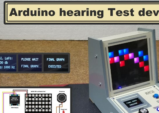
Arduino hearing test device - Audiometer
An audiometer is a machine used for evaluating hearing acuity. They usually consist of an embedded hardware unit connected to a pair of headphones and a test subject feedback button. This device typically transmits pure tones to the headphones of the test subject at varying frequencies and intensities, and records the subject's responses to produce an audiogram of threshold sensitivity.
I recently took a hearing test in a professional facility, and I received the results in the form of an audiogram. I decided to try to make a similar device because the principle of operation of the device is quite simple. After a short research on the internet I found applications that use the sound card of the PC for this purpose, but my goal was to make a practical stand-alone device. I found idea for this type of device on the Arduino forums by a user named "cstram" and decided to make it with some modifications depending on the hardware I had at the time. In this case, the Arduino is an input-output unit that generates tones with different frequencies and intensity, and then displays the feedback results received from the person being tested, on a screen with a resolution of 8 x 8 pixels made up of 64 RGB LEDs. The screen displays two graphs in different colors, for the left and right ear.
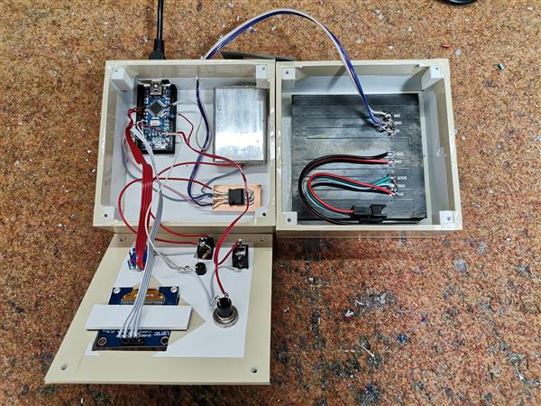
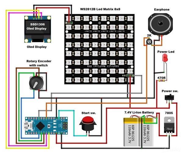
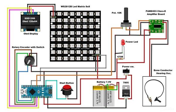
The device is relatively simple to build, and consists of several components:
- Arduino Nano microcontroller
- 8x8 matrix consist of 64 RGB Leds with buit-in WS2812 chip. For a more interesting visual impression, I made a 3D printed grid
- 128x64 Oled display with SSD1306 chip
- Rotary encoder
- push button
- female earphone jack
- and small earphones
The device is powered by two lithium batteries connected in series, and a 7805 5V voltage stabilizer is placed at its output. This time I neglected the battery control and charging circuit because that part has been described several times before.
If you want to make your own PCB for this project, or for any other electronic project, PCBway is a great choice for you. PCBway is one of the most experienced PCB manufacturing company in China in field of PCB prototype and fabrication. They have a large online community where you can find a Open Source projects, and you can also share your project there. From my personal experience I can tell you that on this community you can find many useful projects with alredy designed PCBs, from where you can place an order directly.

Now let's see how the device works in reality: When turning on the device, the first test frequency and the volume in decibels appear on the Oled screen. On the Matrix screen, the rows represent the sound volume in decibels and the columns represent the given frequency in Hertz. Now we put the earphone in one ear and using the rotary encoder we gradually increase the volume until we hear a sound. At that moment, we press the button, which remembers the result for the first frequency and switches to the next frequency, and thus we go to the end. When we finish with the last frequency, we switch the earphone to the other ear and repeat the procedure for all frequencies. Now the diodes will light up with a different color. At the end, the device plots the audiograms for both ears individually in red and blue. The display will give us all the information required. This will tell you the quality of you hearing at each frequency. The red color represents the left ear, while the blue color represents the right one. Let me mention that this is not a professional device and can be used for fun. However, if we calibrate it using a professional device, as I did, we can get quite a solid insight into the auditory capabilities of our hearing organs.
This is what a professional Audiogram looks like:

UPDATE:
A few days after I finished the project, I had access to the Bone Conduction Headset, which is used for Bone Conduction Testing.

This is another type of pure-tone test that measures your inner ear’s response to sound. A conductor will be placed behind your ear; it will send tiny vibrations through the bone directly to the inner ear. This is different than the traditional version, which uses air to send audible sounds. If the results of this test are different than the pure-tone audiometry, your audiologist can use this information to determine your type of hearing loss. Determining the threshold should be done in the same way as obtaining the Air Conduction thresholds is performed. Bone-conduction measurements are normally restricted to the frequency range from 250 to 4000 Hz. With a small modification of the previously described device, I expanded its functionality, and after that Bone Conduction Testing can also be performed with it.
It is only necessary to add a small audio amplifier because the ohmic resistance of the test headset vibrator is only four ohms. I used a small inexpensive class D amplifier with a potentiometer which is quite suitable for this purpose.
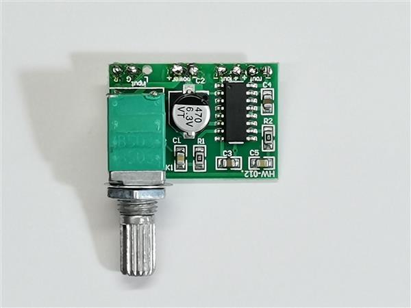
It is only necessary to bring the signal from headphones to the input of the amplifier. A Bone Conduction headset is connected to the output of the amplifier through a suitable connector. With the help of the potentiometer we can perform a precise calibration using a commercial device like this. So, as I mentioned before, the method of performing the test is exactly the same as in the previous case, only that instead of a headset, a Bone Conduction oscolator is placed on the bone behind the ear.
Finally, the device is installed in a suitable case made of PVC board and covered with colored wallpaper.
#include <Volume.h>
#include <RotaryEncoder.h>
#include <Adafruit_NeoPixel.h>
#include <OneButton.h>
#include <U8glib.h>

#define PIN 8
Adafruit_NeoPixel strip = Adafruit_NeoPixel(64, PIN, NEO_GRB + NEO_KHZ800);
U8GLIB_SSD1306_128X64 u8g(U8G_I2C_OPT_NONE);  // I2C / TWI

Volume vol;
// Change these two numbers to the pins connected to your encoder.
//   Best Performance: both pins have interrupt capability
//   Good Performance: only the first pin has interrupt capability
//   Low Performance:  neither pin has interrupt capability

// ----- Rotary settings here ----
#define ROTARYSTEPS 1
#define ROTARYMIN 1
#define ROTARYMAX 8
int lastPos = 0;
int exitFlag = 0;
// Setup a RoraryEncoder for pins A2 and A3:
 RotaryEncoder encoder(A2, A3);

// Last known rotary position.
// Setup a new OneButton on pin A1.
OneButton button(A1, true);

int risultati[3][8];
int j=0;
int x=0;
int y=0;
int orecchio=1;
int pos = 1;
char db[9][10]=
{ "0 db",
  "10 db",
  "20 db",
  "30 db",
  "40 db",
  "50 db",
  "60 db",
  "70 db",
  "80 db"
};
char freq[8][10]
{ "125 Hz",
  "250 Hz",
  "500 Hz",
  "1000 Hz",
  "2000 Hz",
  "3000 Hz",
  "4000 Hz",
  "8000 Hz"
};

int freqn[8][2]
{
  125, 250, 500, 1000, 2000, 3000, 4000, 8000
};

char ear[3][11]
{ "Volume:",
  "Vol. Left:",
  "Vol. Righ:"
};


void setup() {
  strip.begin();
  strip.show(); // Initialize all pixels to 'off'

  encoder.setPosition(0 / ROTARYSTEPS); // start with the value of 0.

  u8g.setColorIndex(1);         // pixel on for Display

  button.attachLongPressStop(longPressStop);


  vol.begin(); // After calling this, delay() and delayMicroseconds will no longer work
               // correctly! Instead, use vol.delay() and vol.delayMicroseconds() for
               // the correct timing

  vol.setMasterVolume(3.00); // Self-explanatory enough, right? Try lowering this value if the speaker is too loud! (0.00 - 1.00)
  vol.delay(500);

  Serial.begin(115200);
  Serial.println("Volume test with Encoder:");

}


void loop() {

  button.tick();

  encoder.tick();

  int newPos = encoder.getPosition();
  if (pos != newPos) {

    if (newPos < ROTARYMIN) {
    encoder.setPosition(ROTARYMIN / ROTARYSTEPS);
    newPos = ROTARYMIN;
    } else if (newPos > ROTARYMAX) {
      encoder.setPosition(ROTARYMAX / ROTARYSTEPS);
      newPos = ROTARYMAX;
    }

    Serial.print(newPos);
    Serial.print(", ");
    Serial.print(x);
    Serial.println();

    if (orecchio < 3){
    u8g.firstPage();
    do {
      draw(ear[orecchio], 25, 16);
      draw("Freq:", 15, 55);
      draw(db[newPos], 40, 35);
      draw(freq[x], 60, 55);
    } while( u8g.nextPage() );
    } else {
      u8g.firstPage();
    do {
      draw("  FINAL GRAPH  ", 0, 20);
      draw("   EXECUTED    ", 0, 50);
    } while( u8g.nextPage() );
    }

    pos = newPos;
    vol.tone (freqn[x],pos);

    if (orecchio < 3)
      for (j=(x*8); j<64;j++)
        strip.setPixelColor(j, 0, 0, 0);
    strip.show();

    if ((x==0 or x==2 or x==4 or x==6) and orecchio==1)
      strip.setPixelColor((pos-1)+(x*8), 10, 0, 0);
    if ((x==1 or x==3 or x==5 or x==7) and orecchio==1)
      strip.setPixelColor(((x+1)*8)-(pos), 10, 0, 0);
    if ((x==0 or x==2 or x==4 or x==6) and orecchio==2)
      strip.setPixelColor((pos-1)+(x*8), 0, 0, 10);
    if ((x==1 or x==3 or x==5 or x==7) and orecchio==2)
      strip.setPixelColor(((x+1)*8)-(pos), 0, 0, 10);
    strip.show();
    }

//  vol.delay(10); // solo per test

}


// This function will be called once, when the button1 is released after beeing pressed for a long time.
void longPressStop() {
  Serial.print("Button 1 longPress stop, x=");
//  scanf("%d", &risultati[orecchio][pos]);
  risultati[orecchio][x]=pos;
  x=x+1;
  pos=0;
  encoder.setPosition(1);
  if (x>7 and orecchio == 1) {
    x=0;
    orecchio =2;
    }
    if (x>7 and orecchio == 2) {
    u8g.firstPage();
    do  {
      draw("  PLEASE WAIT  ", 0, 20);
      draw("  FINAL GRAPH  ", 0, 50);
        } while( u8g.nextPage() );
      strip.clear();
      for (j=1; j<3;j++) {
        Serial.println();
        for (x=0; x<8;x++) {
          if ((x==0 or x==2 or x==4 or x==6) and j==1)
            strip.setPixelColor((risultati[j][x]-1)+(x*8), 10, 0, 0);
          if ((x==1 or x==3 or x==5 or x==7) and j==1)
            strip.setPixelColor(((x+1)*8)-(risultati[j][x]), 10, 0, 0);
          if ((x==0 or x==2 or x==4 or x==6) and j==2)
            if (strip.getPixelColor((risultati[j][x]-1)+(x*8)) == 0)
              strip.setPixelColor((risultati[j][x]-1)+(x*8), 0, 0, 10);
            else
              strip.setPixelColor((risultati[j][x]-1)+(x*8), 10, 0, 10);
          if ((x==1 or x==3 or x==5 or x==7) and j==2)
            if (strip.getPixelColor(((x+1)*8)-(risultati[j][x])) == 0)
              strip.setPixelColor(((x+1)*8)-(risultati[j][x]), 0, 0, 10);
            else
              strip.setPixelColor(((x+1)*8)-(risultati[j][x]), 10, 0, 10);
          strip.show();
          Serial.print(risultati[j][x]);
          Serial.print(", ");
          vol.delay(1000);
        }

      }
      x=0;
      orecchio = 3;
    }

  Serial.println(x);
  Serial.print("Ear = ");
  Serial.println(orecchio);

} // longPressStop1

void draw(char* parola, int posx, int posy) {
  // graphic commands to redraw the complete screen should be placed here
  u8g.setFont(u8g_font_unifont);
  //u8g.setFont(u8g_font_osb21);
  u8g.drawStr( posx, posy, parola);
}
Arduino hearing test device - Audiometer
Project images are for reference only. Actual production is based on the manufacturing files on the project page.
Please review the designer's notes (e.g., PCB thickness) and select the appropriate options.
PCBWay is not responsible
for issues caused by unsuitable parameter selections.
For more important ordering information, please refer to
Read More


Raspberry Pi 5 7 Inch Touch Screen IPS 1024x600 HD LCD HDMI-compatible Display for RPI 4B 3B+ OPI 5 AIDA64 PC Secondary Screen(Without Speaker)
BUY NOW


- Comments(0)
- Likes(1)
More by Mirko Pavleski
-
 Arduino 3D Printed self Balancing Cube
Self-balancing devices are electronic devices that use sensors and motors to keep themselves balanc...
Arduino 3D Printed self Balancing Cube
Self-balancing devices are electronic devices that use sensors and motors to keep themselves balanc...
-
 Elecrow All-in-One Arduino Starter Kit Review - 20 Projects & 16 Modules
This time I will describe a simple and practical way to enter the world of microcontrollers, specif...
Elecrow All-in-One Arduino Starter Kit Review - 20 Projects & 16 Modules
This time I will describe a simple and practical way to enter the world of microcontrollers, specif...
-
 ESP32-C3 Color Detector with TCS34725, Real-Time RGB Detection & Web Interface
Color detection is a fundamental task in many embedded systems – from industrial sorting machines t...
ESP32-C3 Color Detector with TCS34725, Real-Time RGB Detection & Web Interface
Color detection is a fundamental task in many embedded systems – from industrial sorting machines t...
-
 DIY ESP32 Telegram Flood Protection System - Smart Home Automation
Recently I had an unpleasant experience in my home, specifically my ground floor was flooded as a r...
DIY ESP32 Telegram Flood Protection System - Smart Home Automation
Recently I had an unpleasant experience in my home, specifically my ground floor was flooded as a r...
-
 Real-Time Air Traffic Radar using ESP32 + ADS-B Data
ADS-B, which stands for Automatic Dependent Surveillance-Broadcast, is the modern standard for trac...
Real-Time Air Traffic Radar using ESP32 + ADS-B Data
ADS-B, which stands for Automatic Dependent Surveillance-Broadcast, is the modern standard for trac...
-
 DIY Green Laser Night Sky Object Finder - Find Stars & Galaxies Instantly with great accuracy
As an amateur astronomer, especially at the beginning, the most difficult part of observing the nig...
DIY Green Laser Night Sky Object Finder - Find Stars & Galaxies Instantly with great accuracy
As an amateur astronomer, especially at the beginning, the most difficult part of observing the nig...
-
 DIY Avionics Simulator with ESP32 - Artificial Horizon, Compass & Altimeter
The inspiration for this project comes from classical aircraft cockpit instruments used for navigat...
DIY Avionics Simulator with ESP32 - Artificial Horizon, Compass & Altimeter
The inspiration for this project comes from classical aircraft cockpit instruments used for navigat...
-
 DIY Miniature X-Ray Machine using a TV Vacuum Tube DY86
An X-ray machine (or radiograph) is a quick, painless medical test that produces images of the struc...
DIY Miniature X-Ray Machine using a TV Vacuum Tube DY86
An X-ray machine (or radiograph) is a quick, painless medical test that produces images of the struc...
-
 Simple SDR Receiver Using 2x NE612 - Dual Conversion, Superheterodyne (0.1–30 MHz)
SDR (Software Defined Radio) is a radio system in which most of the functions of a classic radio (f...
Simple SDR Receiver Using 2x NE612 - Dual Conversion, Superheterodyne (0.1–30 MHz)
SDR (Software Defined Radio) is a radio system in which most of the functions of a classic radio (f...
-
 DIY Vintage TV VU Meter with peak indicators
Some time ago in one of my projects I presented you a way to turn a black and white old mini TV int...
DIY Vintage TV VU Meter with peak indicators
Some time ago in one of my projects I presented you a way to turn a black and white old mini TV int...
-
 DIY Tesla Coil based Plasma Rife Machine
In several of my previous videos, I presented you with different ways to make a Rife Machine, from ...
DIY Tesla Coil based Plasma Rife Machine
In several of my previous videos, I presented you with different ways to make a Rife Machine, from ...
-
 ESP32 Analog VU Meter – Smooth Needle, Real Audio Response (DIY Build)
In several of my previous videos I have shown you how to make analog VU meters emulated on differen...
ESP32 Analog VU Meter – Smooth Needle, Real Audio Response (DIY Build)
In several of my previous videos I have shown you how to make analog VU meters emulated on differen...
-
 The Ultimate Smartphone VFO ESP32 & Si5351 Wireless Control
Variable frequency oscillators (VFOs) are commonly used in radio transmitters and receivers, especi...
The Ultimate Smartphone VFO ESP32 & Si5351 Wireless Control
Variable frequency oscillators (VFOs) are commonly used in radio transmitters and receivers, especi...
-
 DIY Shortwave Propagation Monitor - Measure Ionosphere Conditions
Shortwave Propagation is the way radio waves in the 3 to 30 MHz range travel from point A to point ...
DIY Shortwave Propagation Monitor - Measure Ionosphere Conditions
Shortwave Propagation is the way radio waves in the 3 to 30 MHz range travel from point A to point ...
-
 Professional grade Smart Lock with ESP32, BLE and Android App Control
An electronic codelock is a security device that grants access using a numerical sequence—a PIN cod...
Professional grade Smart Lock with ESP32, BLE and Android App Control
An electronic codelock is a security device that grants access using a numerical sequence—a PIN cod...
-
 Building a 3-Input Stereo ECC83 (12AX7) Tube Preamp
Some time ago I presented you a project for a 3W stereo tube amplifier with a GU32 output vacuum t...
Building a 3-Input Stereo ECC83 (12AX7) Tube Preamp
Some time ago I presented you a project for a 3W stereo tube amplifier with a GU32 output vacuum t...
-
 ESP32 Weather Dashboard with Satellite Maps and 16-day Weather Forecast
As you can see from my previous videos, besides Electronics, my fields of experimentation and proje...
ESP32 Weather Dashboard with Satellite Maps and 16-day Weather Forecast
As you can see from my previous videos, besides Electronics, my fields of experimentation and proje...
-
 Retro Analog VU Meter on Round dispalys (ESP32 and GC9A01)
Recently, in one of my previous videos I presented you a Retro VU Meter project on round displays ...
Retro Analog VU Meter on Round dispalys (ESP32 and GC9A01)
Recently, in one of my previous videos I presented you a Retro VU Meter project on round displays ...
-
Programmable Mist Maker - XIAO / QT PY Extension
1102 2 1 -
RadioHAT - Raspberry Pi radio development platform
916 0 2 -
-
-
-
-
ARPS-2 – Arduino-Compatible Robot Project Shield for Arduino UNO
3346 0 6 -
A Compact Charging Breakout Board For Waveshare ESP32-C3
3961 3 8 -
AI-driven LoRa & LLM-enabled Kiosk & Food Delivery System
4349 2 2


