


|
|
Arduino Nano RP2040 ABX00053 (NANO)Arduino
|
x 1 | |
|
|
HPDL-1414 Led displays |
x 2 | |
|
|
Buzzer |
x 1 | |
|
|
button |
x 3 |

|
Soldering iron |
|

|
Soldering Iron Wire |
|

|
arduino IDEArduino
|
Arduino HPDL1414 Retro Clock with Set and Alarm Functions
The HPDL-1414 is a 16-segment LED display with four printable fields that is over twenty years old. It has a red GaAsP screen to which we can add the epithet "smart", because it is capable of printing alphanumeric characters on its fields.

The screen is controlled by a CMOS integrated circuit embedded in a plastic housing.This circuit contains RAM, ASCI II decoder, multiplexer and LED drivers. Thanks to these features, no additional components are needed to connect this display to the microcontroller. More displays can be connected in series, where for each subsequent one it is necessary to assign another GPIO to the WR pin, similar to the SPI interface.
In one of my previous videos I presented you a miniature clock with these displays, as well as the way in which static and moving text can be written on it. Unfortunately at that moment I didn't manage to create a version of the code in which I could adjust the time manually with buttons, which would make this nice retro clock complete, although when making the case I incorporated three buttons for this purpose.
This time I will present you the new version of this project, where in addition to manually setting the time, I also added a Alarm function with a pulsating beep on a small Buzzer.
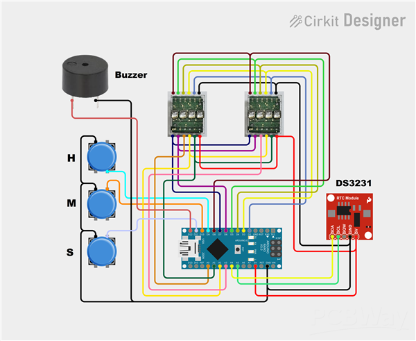
The device is very simple to make and consists of several components:
- Arduino nano microcontroller
- 2 pcs. HPDL-1414 Led displays
- DS3231 Realtime clock module
- Three Buttons,
- And small active Buzzer

This project is sponsored by PCBWay. This year, PCBWay organizes the Seventh Project Design Contest where, in addition to Electronic and Mechanical Project, also has been added a new category: STM32 Project. For the best selected projects are provided rich prizes in cash, coupons and special gifts. Submit your project for participation in this Contest from 2nd, Sep, 2024 to 19th, Jan, 2025. For more details and instructions visit the given page. Let PCBway always be your first choice.

Now follows a brief description of the device's functions. Immediately after switching on, a moving demo text appears on the display, after which the set time is displayed in the form of Hours, Minutes, and Seconds. To enter the menu for setting the correct time, press the "S" button.

Now with the "H" button the hour is set, and with the "M" button the minutes are set. With the next click on the "S" button, we enter the menu for setting the alarm.

The setting principle is the same as before, only this time the letter "A" appears at the beginning, unlike the previous menu.
The alarm is activated at the set time in the form of short beeps with a duration of 500mS, and is deactivated simply by pressing the set button.
And finally a short conclusion. This is a small, simple, but really interesting unusual clock that shows the time on retro displays made by Hewlett-Packard at the turn of the last century, and was also used for calculators and measuring instruments.
#include <HPDL1414.h>
#include <RTClib.h>
#include <Wire.h>

const byte dataPins[7] = {2, 3, 4, 5, 6, 7, 8};  // Segment data pins: D0 - D6
const byte addrPins[2] = {A1, A2};               // Segment address pins: A0, A1
const byte wrenPins[] = {A0, A3};                // Write Enable pins (left to right)

RTC_DS3231 rtc;
char msg[] = "         *** MICRO CLOCK - MIRCEMK ***        ";
char t[32];
HPDL1414 hpdl(dataPins, addrPins, wrenPins, sizeof(wrenPins));

// Button pins
const int buttonHourPin = 9;
const int buttonMinutePin = 10;
const int buttonSetPin = 11;

// Buzzer pin
const int buzzerPin = 12;  // Add a pin for the buzzer

// Variables for setting time and alarm manually
int hours = 0;
int minutes = 0;
int alarmHours = 0;
int alarmMinutes = 0;
bool setMode = false;      // Time setting mode flag
bool alarmMode = false;    // Alarm setting mode flag
bool alarmEnabled = false; // Alarm enabled flag
bool alarmActive = false;  // Alarm active (sounding) flag
bool alarmAcknowledged = false; // Alarm acknowledged (stopped) flag

// Buzzer timing
unsigned long previousMillis = 0;
const long beepInterval = 500;  // 500ms on, 500ms off
bool buzzerState = false;       // To track buzzer state (on/off)

void setup() {
  Serial.begin(9600);
  Wire.begin();
  hpdl.begin();
  hpdl.clear();

  // Set up buttons and buzzer
  pinMode(buttonHourPin, INPUT_PULLUP);
  pinMode(buttonMinutePin, INPUT_PULLUP);
  pinMode(buttonSetPin, INPUT_PULLUP);
  pinMode(buzzerPin, OUTPUT);
  digitalWrite(buzzerPin, LOW);  // Make sure the buzzer is off initially

  // Display scrolling message at startup
  for (byte i = 0; i < (sizeof(msg) / sizeof(char)); i++) {
    for (byte j = 0; j < 16; j++) {
      hpdl.setCursor(j);
      if (i + j < (sizeof(msg) / sizeof(char))) {
        hpdl.print(msg[i + j]);
      } else {
        hpdl.print(" ");
      }
    }
    delay(200);
  }

  rtc.begin();
  // Initialize time variables from the RTC
  DateTime now = rtc.now();
  hours = now.hour();
  minutes = now.minute();
}

void loop() {
  // Get the current time from the RTC
  DateTime now = rtc.now();

  // Check if the alarm is active (buzzer sounding)
  if (alarmActive) {
    unsigned long currentMillis = millis();

    // Toggle the buzzer every 500ms (buzzerState controls on/off)
    if (currentMillis - previousMillis >= beepInterval) {
      previousMillis = currentMillis;  // Save the last time the buzzer toggled
      buzzerState = !buzzerState;      // Toggle the buzzer state
      digitalWrite(buzzerPin, buzzerState ? HIGH : LOW);  // Turn the buzzer on or off
    }

    // Check if D11 is pressed to stop the alarm
    if (digitalRead(buttonSetPin) == LOW) {
      alarmActive = false;  // Stop the alarm
      alarmAcknowledged = true;  // Mark the alarm as acknowledged
      digitalWrite(buzzerPin, LOW);  // Turn off the buzzer
      delay(500);  // Debounce delay
      return;  // Return to normal loop operation
    }
  }

  // Check if we are in time or alarm setting mode
  if (setMode) {
    // Display the manually set time
    sprintf(t, "%02d-%02d", hours, minutes);
    hpdl.clear();
    hpdl.print(t);

    // Check if buttons to adjust hours or minutes are pressed
    if (digitalRead(buttonHourPin) == LOW) {
      hours = (hours + 1) % 24;  // Increment hours and roll over after 23
      delay(200);  // Debouncing
    }
    if (digitalRead(buttonMinutePin) == LOW) {
      minutes = (minutes + 1) % 60;  // Increment minutes and roll over after 59
      delay(200);  // Debouncing
    }
  } else if (alarmMode) {
    // Display the manually set alarm time
    sprintf(t, "A%02d-%02d", alarmHours, alarmMinutes);
    hpdl.clear();
    hpdl.print(t);

    // Check if buttons to adjust alarm hours or minutes are pressed
    if (digitalRead(buttonHourPin) == LOW) {
      alarmHours = (alarmHours + 1) % 24;  // Increment alarm hours and roll over after 23
      delay(200);  // Debouncing
    }
    if (digitalRead(buttonMinutePin) == LOW) {
      alarmMinutes = (alarmMinutes + 1) % 60;  // Increment alarm minutes and roll over after 59
      delay(200);  // Debouncing
    }
  } else {
    // Normal operation: Display the current time from the RTC
    sprintf(t, "%02d-%02d-%02d", now.hour(), now.minute(), now.second());
    hpdl.clear();
    hpdl.print(t);

    // Check if the current time matches the alarm time and alarm is not acknowledged
    if (alarmEnabled && !alarmAcknowledged && now.hour() == alarmHours && now.minute() == alarmMinutes && now.second() == 0) {
      alarmActive = true;  // Mark the alarm as active
      previousMillis = millis();  // Initialize the timer for buzzer beeping
    }

    // Reset the alarm acknowledgement flag if the minute has changed
    if (now.minute() != alarmMinutes) {
      alarmAcknowledged = false;  // Allow the alarm to trigger again when the time matches next
    }
  }

  // Check if the Set button (buttonSetPin) is pressed to toggle between modes
  if (digitalRead(buttonSetPin) == LOW && !alarmActive) {
    if (setMode) {
      // Exiting time set mode, update the RTC with the manually set time
      rtc.adjust(DateTime(2024, 1, 1, hours, minutes, 0));  // Arbitrary date
      setMode = false;
      alarmMode = true;  // Move to alarm setting mode
    } else if (alarmMode) {
      // Exiting alarm set mode, enable the alarm
      alarmEnabled = true;
      alarmMode = false; // Back to normal mode
    } else {
      // Enter time setting mode
      setMode = true;
    }
    delay(500);  // Debouncing delay
  }
}
Arduino HPDL1414 Retro Clock with Set and Alarm Functions


Raspberry Pi 5 7 Inch Touch Screen IPS 1024x600 HD LCD HDMI-compatible Display for RPI 4B 3B+ OPI 5 AIDA64 PC Secondary Screen(Without Speaker)
BUY NOW


- Comments(0)
- Likes(0)
More by Mirko Pavleski
-
 Arduino 3D Printed self Balancing Cube
Self-balancing devices are electronic devices that use sensors and motors to keep themselves balanc...
Arduino 3D Printed self Balancing Cube
Self-balancing devices are electronic devices that use sensors and motors to keep themselves balanc...
-
 Elecrow All-in-One Arduino Starter Kit Review - 20 Projects & 16 Modules
This time I will describe a simple and practical way to enter the world of microcontrollers, specif...
Elecrow All-in-One Arduino Starter Kit Review - 20 Projects & 16 Modules
This time I will describe a simple and practical way to enter the world of microcontrollers, specif...
-
 ESP32-C3 Color Detector with TCS34725, Real-Time RGB Detection & Web Interface
Color detection is a fundamental task in many embedded systems – from industrial sorting machines t...
ESP32-C3 Color Detector with TCS34725, Real-Time RGB Detection & Web Interface
Color detection is a fundamental task in many embedded systems – from industrial sorting machines t...
-
 DIY ESP32 Telegram Flood Protection System - Smart Home Automation
Recently I had an unpleasant experience in my home, specifically my ground floor was flooded as a r...
DIY ESP32 Telegram Flood Protection System - Smart Home Automation
Recently I had an unpleasant experience in my home, specifically my ground floor was flooded as a r...
-
 Real-Time Air Traffic Radar using ESP32 + ADS-B Data
ADS-B, which stands for Automatic Dependent Surveillance-Broadcast, is the modern standard for trac...
Real-Time Air Traffic Radar using ESP32 + ADS-B Data
ADS-B, which stands for Automatic Dependent Surveillance-Broadcast, is the modern standard for trac...
-
 DIY Green Laser Night Sky Object Finder - Find Stars & Galaxies Instantly with great accuracy
As an amateur astronomer, especially at the beginning, the most difficult part of observing the nig...
DIY Green Laser Night Sky Object Finder - Find Stars & Galaxies Instantly with great accuracy
As an amateur astronomer, especially at the beginning, the most difficult part of observing the nig...
-
 DIY Avionics Simulator with ESP32 - Artificial Horizon, Compass & Altimeter
The inspiration for this project comes from classical aircraft cockpit instruments used for navigat...
DIY Avionics Simulator with ESP32 - Artificial Horizon, Compass & Altimeter
The inspiration for this project comes from classical aircraft cockpit instruments used for navigat...
-
 DIY Miniature X-Ray Machine using a TV Vacuum Tube DY86
An X-ray machine (or radiograph) is a quick, painless medical test that produces images of the struc...
DIY Miniature X-Ray Machine using a TV Vacuum Tube DY86
An X-ray machine (or radiograph) is a quick, painless medical test that produces images of the struc...
-
 Simple SDR Receiver Using 2x NE612 - Dual Conversion, Superheterodyne (0.1–30 MHz)
SDR (Software Defined Radio) is a radio system in which most of the functions of a classic radio (f...
Simple SDR Receiver Using 2x NE612 - Dual Conversion, Superheterodyne (0.1–30 MHz)
SDR (Software Defined Radio) is a radio system in which most of the functions of a classic radio (f...
-
 DIY Vintage TV VU Meter with peak indicators
Some time ago in one of my projects I presented you a way to turn a black and white old mini TV int...
DIY Vintage TV VU Meter with peak indicators
Some time ago in one of my projects I presented you a way to turn a black and white old mini TV int...
-
 DIY Tesla Coil based Plasma Rife Machine
In several of my previous videos, I presented you with different ways to make a Rife Machine, from ...
DIY Tesla Coil based Plasma Rife Machine
In several of my previous videos, I presented you with different ways to make a Rife Machine, from ...
-
 ESP32 Analog VU Meter – Smooth Needle, Real Audio Response (DIY Build)
In several of my previous videos I have shown you how to make analog VU meters emulated on differen...
ESP32 Analog VU Meter – Smooth Needle, Real Audio Response (DIY Build)
In several of my previous videos I have shown you how to make analog VU meters emulated on differen...
-
 The Ultimate Smartphone VFO ESP32 & Si5351 Wireless Control
Variable frequency oscillators (VFOs) are commonly used in radio transmitters and receivers, especi...
The Ultimate Smartphone VFO ESP32 & Si5351 Wireless Control
Variable frequency oscillators (VFOs) are commonly used in radio transmitters and receivers, especi...
-
 DIY Shortwave Propagation Monitor - Measure Ionosphere Conditions
Shortwave Propagation is the way radio waves in the 3 to 30 MHz range travel from point A to point ...
DIY Shortwave Propagation Monitor - Measure Ionosphere Conditions
Shortwave Propagation is the way radio waves in the 3 to 30 MHz range travel from point A to point ...
-
 Professional grade Smart Lock with ESP32, BLE and Android App Control
An electronic codelock is a security device that grants access using a numerical sequence—a PIN cod...
Professional grade Smart Lock with ESP32, BLE and Android App Control
An electronic codelock is a security device that grants access using a numerical sequence—a PIN cod...
-
 Building a 3-Input Stereo ECC83 (12AX7) Tube Preamp
Some time ago I presented you a project for a 3W stereo tube amplifier with a GU32 output vacuum t...
Building a 3-Input Stereo ECC83 (12AX7) Tube Preamp
Some time ago I presented you a project for a 3W stereo tube amplifier with a GU32 output vacuum t...
-
 ESP32 Weather Dashboard with Satellite Maps and 16-day Weather Forecast
As you can see from my previous videos, besides Electronics, my fields of experimentation and proje...
ESP32 Weather Dashboard with Satellite Maps and 16-day Weather Forecast
As you can see from my previous videos, besides Electronics, my fields of experimentation and proje...
-
 Retro Analog VU Meter on Round dispalys (ESP32 and GC9A01)
Recently, in one of my previous videos I presented you a Retro VU Meter project on round displays ...
Retro Analog VU Meter on Round dispalys (ESP32 and GC9A01)
Recently, in one of my previous videos I presented you a Retro VU Meter project on round displays ...
-
Programmable Mist Maker - XIAO / QT PY Extension
1082 2 1 -
RadioHAT - Raspberry Pi radio development platform
898 0 2 -
-
-
-
-
ARPS-2 – Arduino-Compatible Robot Project Shield for Arduino UNO
3339 0 6 -
A Compact Charging Breakout Board For Waveshare ESP32-C3
3951 3 8 -
AI-driven LoRa & LLM-enabled Kiosk & Food Delivery System
4340 2 2


