


|
Soldering Iron Kit |
|

|
arduino IDEArduino
|
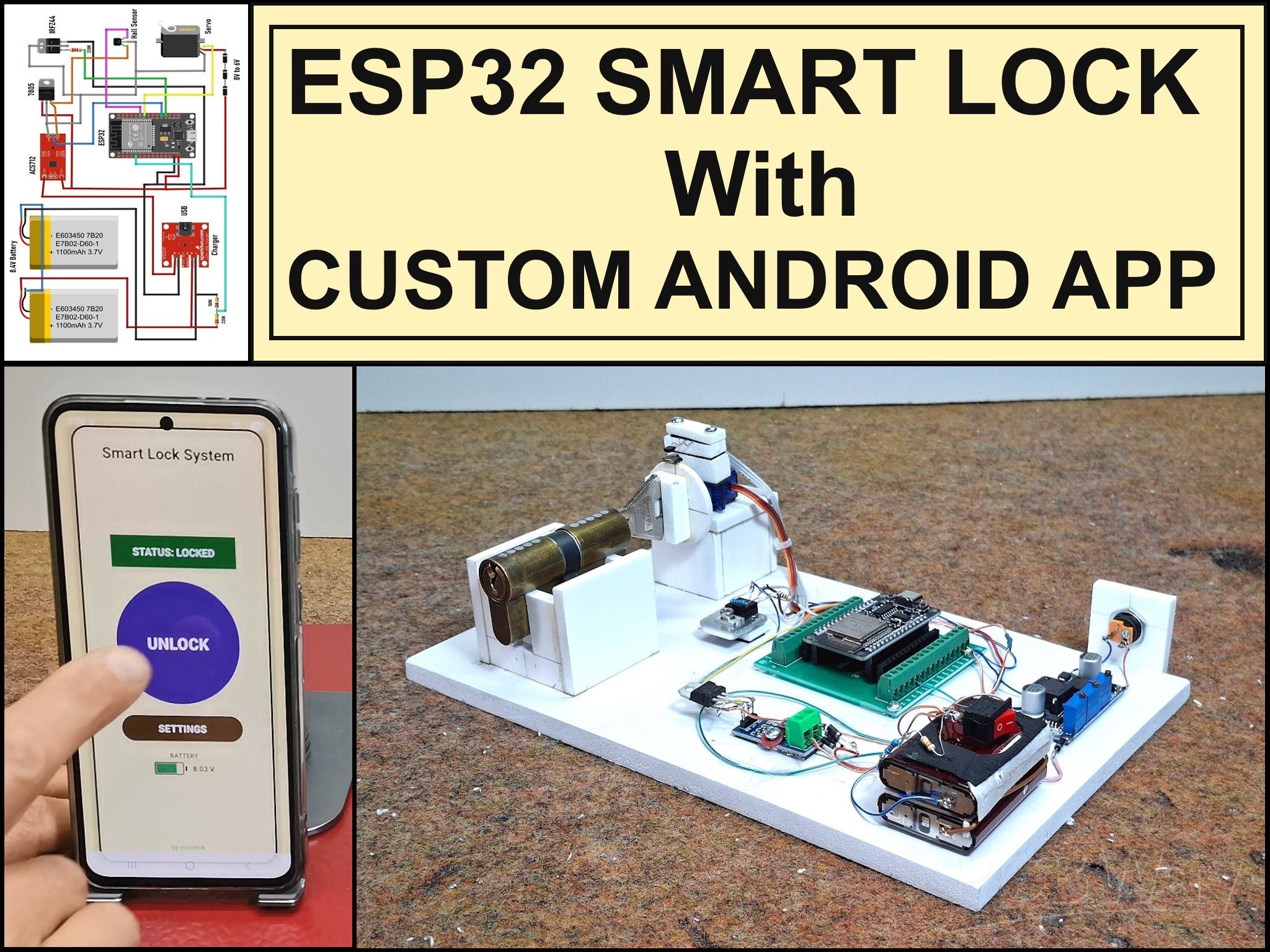
Professional grade Smart Lock with ESP32, BLE and Android App Control
An electronic codelock is a security device that grants access using a numerical sequence—a PIN code—rather than a traditional physical key. These systems are common in offices, apartment complexes, and increasingly, modern "smart" homes.
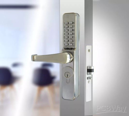
In some of my previous videos, I described several different ways to make a simple electronic codelock. This time I will show you how I developed and built a prototype for a real code-lock, which in its characteristics is much more advanced than many commercial devices of this kind.
The test prototype contains a real mechanical lock with standard dimensions. During the development, I gradually solved the problems one by one. I decided to use standard components that are easily available on the market and are relatively inexpensive.
Here is what the mechanical-electronic part looks like, made on a plastic board for greater visibility and easy modification if necessary during development.

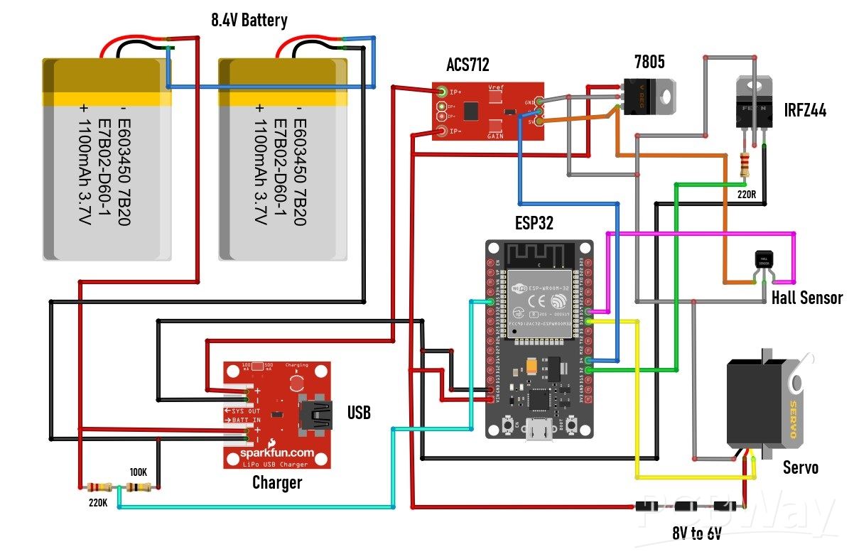
I'll start with the electronic components:
- The heart of the lock is an ESP32 MCU board specifically placed on a suitable socket adapted for easy modification without soldering.
- Then a battery pack of two series-connected Li-Ion batteries that provide a voltage of 7 to 8 V.
- At the moment I didn't have a charger for such batteries, so I used this Constant current/constant voltage stabilizer. I set the output voltage to 8.4V and the constant current to 0.6A. In this way, the board successfully performs the task of a charger.
- Then we have two resistors in a voltage divider connection that bring the appropriate voltage level to the D2 pin of the MCU. In this way, the battery capacity is measured.
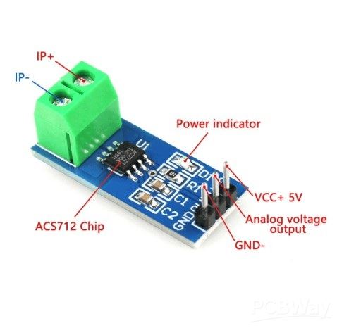
- Small board is an ACS712 current sensor and serves to protect the Motor. The sensor measures the current through the motor and if it exceeds a predefined maximum value (this happens for example if the lock gets stuck and stays in one place), then the MCU turns off the voltage supply to the motor.
- Next is a 5V regulator that provides power to the current sensor and the Hall effect sensor.
- Small cooler has a MOSFET transistor mounted with two resistors and its purpose is to turn off all circuits when the lock is idle. This way, huge battery savings are achieved, which is crucial in this type of device.
- Next comes a very important part, which is a combination of a Hall effect sensor and a permanent magnet, which determines the initial home position of the key. This greatly simplifies and secures the way the MCU controls the lock.
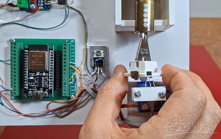
- And finally, the motor that moves the key in the lock. In this prototype, I use a small, cheap servo modified in a way that it can move continuously in any direction. We will not dwell on the method of modification here because it is explained in detail in many videos and the procedure is relatively easy. I chose this particular way of moving the lock because of its universality. If in the final product we use a larger servo with metal gears, then there is no need for any changes to the code, but also with minimal changes, a brushless motor with a bidirectional driver, or a regular motor with an H-bridge driver can be used.
- I also made a special bearing for the lock, so that the motor can move the key left and right, so that we have approximately realistic conditions during testing.
- Otherwise, all this electronics, using SMD components, can be placed on a PCB slightly larger than an MCU dev board.
Now let's move on to the software part. The code is made in a way that almost every phase of the lock's operation can be changed at the very beginning without having to walk through the entire code
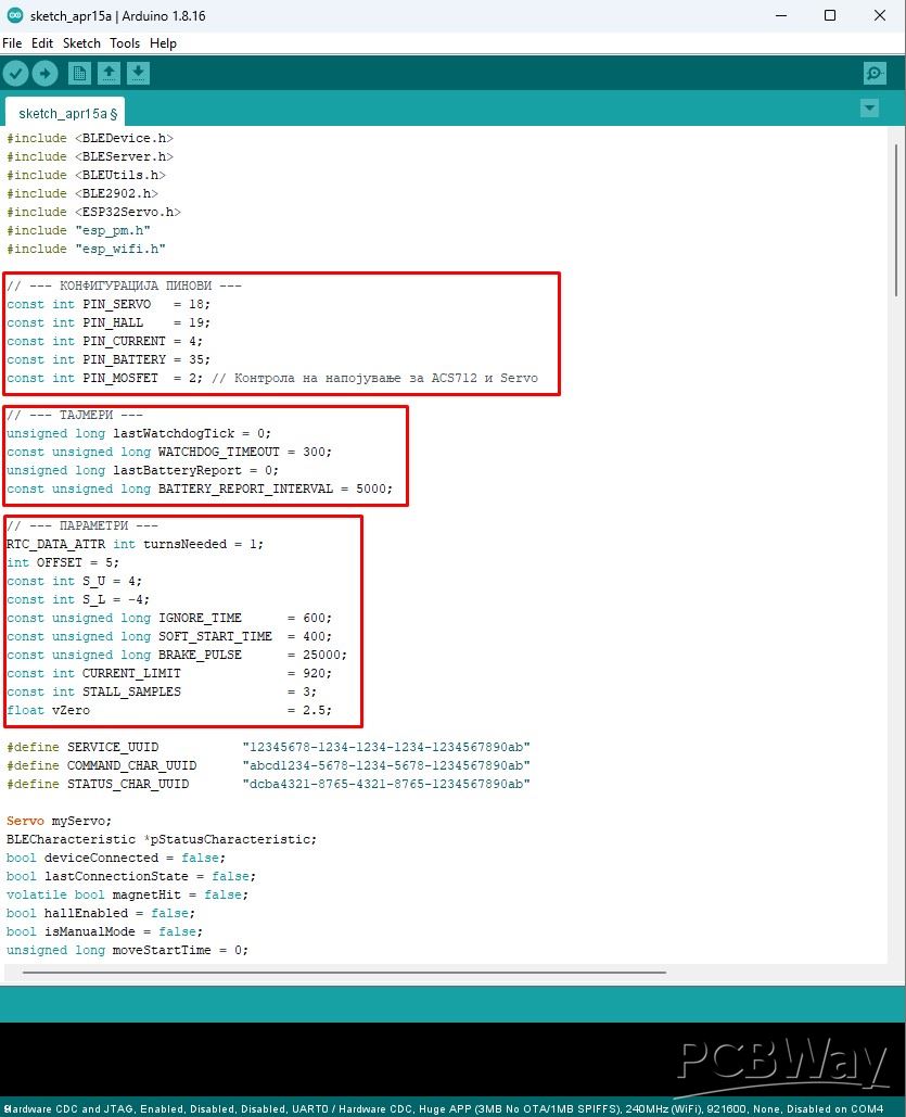
This is a crucial requirement in this type of development project, because very often when testing and changing components, quick changes need to be made to the code. I will describe all the variables that can be changed directly, as well as their functions in the circuit:
- At the beginning, all 5 pins of the ESP32 used in this project are defined.
- Then comes the interval at which data about the battery status is sent.
- Offset is the value at which the servo stops when no movement command is sent. This value depends on the accuracy of the two resistors that are built into the modified servo.
- With S-U and S-L the speed of movement of the servo during Unlocking and Locking is defined.
- IGNORE_TIME is the time during which the Hall sensor is turned off when sending a command to the motor. Specifically, if this variable is 0, the motor will never start.
- SOFT_START_TIME is the time after which the motor will start moving. This allows current peaks during motor start-up to not be measured, which could give a false alarm for a stalled motor.
- BRAKE_PULSE defined in microseconds is used for fine tuning so that the magnet should stop exactly under the HOME hall sensor. This "brake" value is determined purely experimentally and depends on the motor used.
- CURRENT_LIMIT is the current value in milliamperes above which the motor is signaled to be stalled and a command to shut it down is sent.
- To avoid false alarms for a stalled motor, it is stopped only if there is a certain number of consecutive measurements above the previously set current limit. This number of consecutive measurements is defined by STALL_SAMPLES.
- Finally, float vZero is used for calibration to display the correct battery voltage value.
For access control and password entry, I use a smartphone with an Android application, which by the way is my first Android application. It probably could have been done much more professionally, but that wasn't my primary goal in this case, but rather a way to have full control over the lock. When activating the application, a field for entering a pin appears, which is the simplest possible protection.
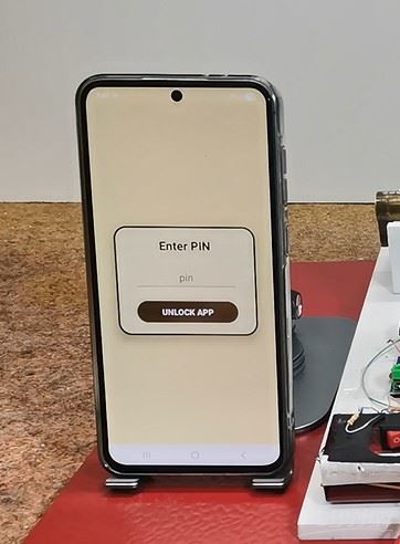
I mentioned earlier that this is my first Android application and I did not intend to waste a lot of time on its implementation. Otherwise, the security part is extremely important in this project, so multiple priorities and levels of protection should be implemented in the final product. By entering the correct pin, we enter the main menu:
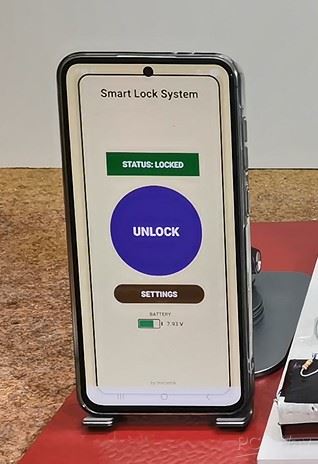
First, the application connects to the lock via BLE connection. Here, the status of the lock (locked or unlocked) is displayed and below it, the state of the battery, which is an integral part of the lock. The state of the battery is accompanied by corresponding different colors. In the middle of the screen, there is a large round button with which we unlock or lock the door. This is the basic user menu and should be enough in 99% of cases when using the code lock. However, sometimes it can happen that the lock gets stuck, or we want to change the number of turns when locking/unlocking. For this purpose, there is another SETTINGS button that enters the next menu.
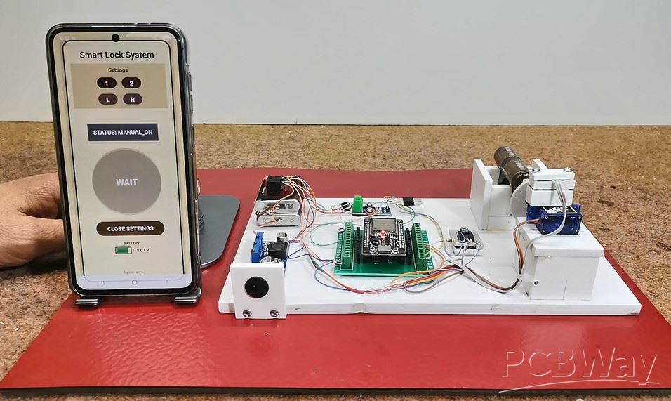
There we have the opportunity to first change the number of turns of the key - one (default) or two as desired. This setup becomes active after exiting the settings screen. Then there are two more buttons marked L and R that are used for manual movement of the motor. This option is very useful in case the key gets stuck, because manual movement is defined in the code in such a way that the servo turns with the greatest force and the current sensor is bypassed. Next comes the most interesting part, and that is how this device behaves in approximately real conditions. I say approximately because what is missing here is the locking/unlocking mechanism that is mounted inside the door. However, today's locks are very precisely made so that only a little more force is needed to move that mechanism. Also, let's not forget that the final product would use a servo that is many times stronger and of higher quality than this $1 serv
Next comes the most interesting part, and that is how this device behaves in approximately real conditions. I say approximately because what is missing here is the locking/unlocking mechanism that is mounted inside the door. However, today's locks are very precisely made so that only a little more force is needed to move that mechanism. Also, let's not forget that the final product would use a servo that is many times stronger and of higher quality than this $1 servo.
Demonstration
Now I will connect an Ammeter to see the total consumption of the device when it is idle. This is actually, besides functionality, the primary goal - to achieve as little consumption as possible when the device is not in use. The duration of the batteries on a single charge depends on this.
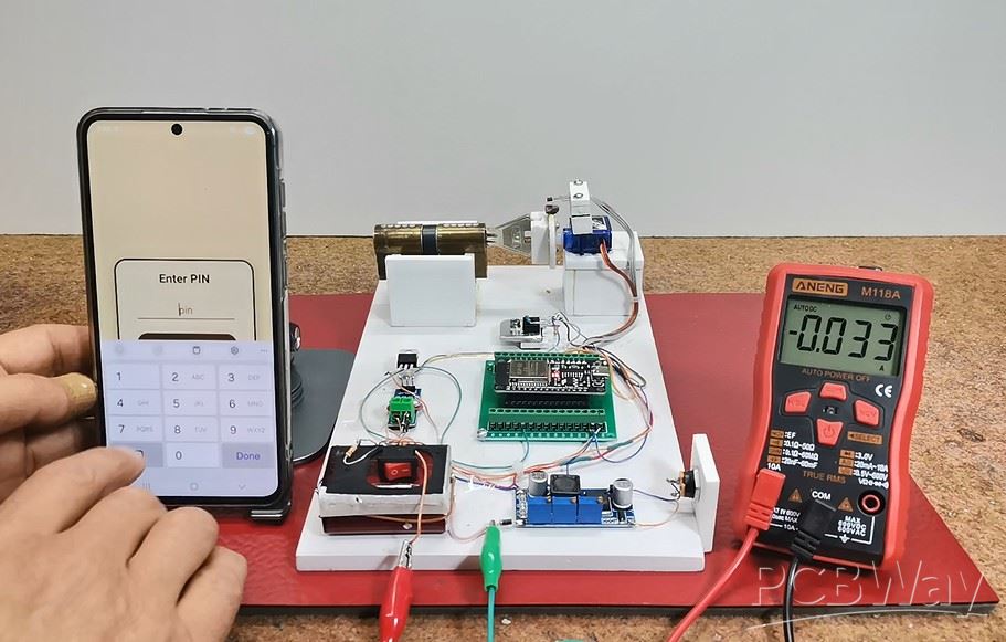
It can be seen that the idle consumption is about 30 mA, seemingly little, but in fact this is a huge value for this type of device. The code includes Light Sleep mode - a compromise between Deep Sleep mode and a normally active MCU. The difference between Light Sleep and Deep Sleep is a few milliamperes, but in Light Sleep mode, connecting to BLE is almost instant, unlike Deep Sleep where it can take tens of seconds or more, which would not be practical at all. Currently, the largest energy consumer is this linear regulator located on the MCU board and which reduces the input voltage from 8V to 3.3V required for normal operation of the ESP32. If I replace this linear regulator with a switching mode regulator (unfortunately, I don't have one at hand at the moment), the total consumption will be reduced to 3 to 5 mA, which is the absolute minimum for the device to function normally with this hardware.
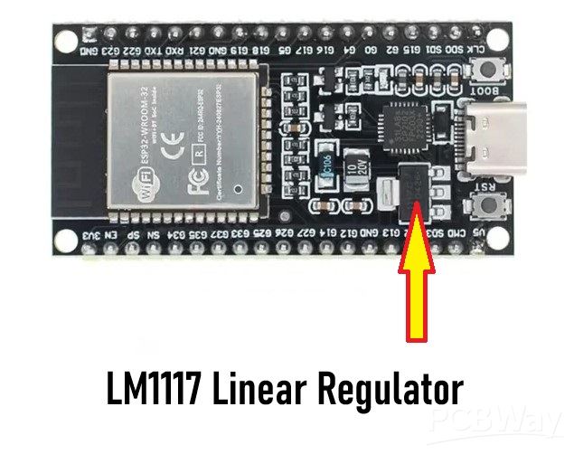
It can be seen that the idle consumption is about 30 mA, seemingly little, but in fact this is a huge value for this type of device. The code includes Light Sleep mode - a compromise between Deep Sleep mode and a normally active MCU. The difference between Light Sleep and Deep Sleep is a few milliamperes, but in Light Sleep mode, connecting to BLE is almost instant, unlike Deep Sleep where it can take tens of seconds or more, which would not be practical at all. Currently, the largest energy consumer is this linear regulator located on the MCU board and which reduces the input voltage from 8V to 3.3V required for normal operation of the ESP32. If I replace this linear regulator with a switching mode regulator (unfortunately, I don't have one at hand at the moment), the total consumption will be reduced to 3 to 5 mA, which is the absolute minimum for the device to function normally with this hardware.
So with all the hardware and software modifications to save power, the average battery would last a maximum of about a week with normal use of the lock. However, it is known that such locks from well-known brand manufacturers can work for three to six months on a single battery charge. The secret is in the use of highly specialized chips designed specifically for such battery-powered devices. One of the manufacturers of such chips intended for industrial use is Nordic Semiconductors, whose specialized chips have several thousand times lower power consumption than, for example, ESP32 in Deep Sleep mode. These chips practically do not consume any power when in standby mode. However, these industrial chips use a special framework developed by the manufacturer, and the way they are programmed is characteristic and different for each series.
And finally, a short conclusion. With this project, you could roughly see how complex and time-consuming the development of a device is, before it reaches commercial production. In particular, this code lock, despite all the measures taken, especially for energy saving, does not meet the standards for a battery-powered device of this type, but it is certainly an excellent basis for further development with specialized chips, taking into account that the programming logic remains exactly the same.
// by mircemk March, 2026

#include <BLEDevice.h>
#include <BLEServer.h>
#include <BLEUtils.h>
#include <BLE2902.h>
#include <ESP32Servo.h>
#include "esp_pm.h"
#include "esp_wifi.h"

// --- КОНФИГУРАЦИЈА ПИНОВИ ---
const int PIN_SERVO   = 18;
const int PIN_HALL    = 19;
const int PIN_CURRENT = 4;
const int PIN_BATTERY = 35;
const int PIN_MOSFET  = 2; // Контрола на напојување за ACS712 и Servo

// --- ТАЈМЕРИ ---
unsigned long lastWatchdogTick = 0;
const unsigned long WATCHDOG_TIMEOUT = 300;
unsigned long lastBatteryReport = 0;
const unsigned long BATTERY_REPORT_INTERVAL = 5000;

// --- ПАРАМЕТРИ ---
RTC_DATA_ATTR int turnsNeeded = 1;
int OFFSET = 5;
const int S_U = 4;
const int S_L = -4;
const unsigned long IGNORE_TIME      = 600;
const unsigned long SOFT_START_TIME  = 400;
const unsigned long BRAKE_PULSE      = 25000;
const int CURRENT_LIMIT              = 920;
const int STALL_SAMPLES              = 3;
float vZero                          = 2.5;

#define SERVICE_UUID           "12345678-1234-1234-1234-1234567890ab"
#define COMMAND_CHAR_UUID      "abcd1234-5678-1234-5678-1234567890ab"
#define STATUS_CHAR_UUID       "dcba4321-8765-4321-8765-1234567890ab"

Servo myServo;
BLECharacteristic *pStatusCharacteristic;
bool deviceConnected = false;
bool lastConnectionState = false;
volatile bool magnetHit = false;
bool hallEnabled = false;
bool isManualMode = false;
unsigned long moveStartTime = 0;
int lastDir = 0;
int stallCounter = 0;
int magnetCount = 0;
String lockStatus = "LOCKED";
String lastKnownValidStatus = "LOCKED";

// --- ПОМОШНИ ФУНКЦИИ ---

void IRAM_ATTR onHall() {
  if (hallEnabled && !isManualMode) magnetHit = true;
}

void updateStatus(String newStatus) {
  lockStatus = newStatus;
  if (newStatus == "LOCKED" || newStatus == "UNLOCKED") lastKnownValidStatus = newStatus;
  pStatusCharacteristic->setValue(lockStatus.c_str());
  pStatusCharacteristic->notify();
}

void stopAction(String finalStatus) {
  int tempDir = lastDir;
  lastDir = 0; moveStartTime = 0; hallEnabled = false; stallCounter = 0; magnetCount = 0;

  if (tempDir == 1) myServo.write(S_L + 90 + OFFSET);
  else if (tempDir == -1) myServo.write(S_U + 90 + OFFSET);

  if (tempDir != 0) ets_delay_us(BRAKE_PULSE);
  myServo.write(90 + OFFSET);

  // ИСКЛУЧИ ПЕРИФЕРИЈА (Штедење енергија)
  digitalWrite(PIN_MOSFET, LOW);

  updateStatus(finalStatus);
}

float readBatteryVoltage() {
  long sum = 0;
  const int samples = 40;
  for (int i = 0; i < samples; i++) {
    sum += analogRead(PIN_BATTERY);
    delayMicroseconds(400);
  }
  float adcRaw = (float)sum / (float)samples;
  float vAdc = (adcRaw / 4095.0f) * 3.3f;
  float vBat = vAdc * 3.2f * 1.1f;
  return vBat;
}

void reportBatteryVoltage() {
  float vb = readBatteryVoltage();
  if (deviceConnected) {
    String msg = "BAT:" + String(vb, 2) + "V";
    pStatusCharacteristic->setValue(msg.c_str());
    pStatusCharacteristic->notify();
  }
}

float readCurrent() {
  long sum = 0;
  for (int i = 0; i < 15; i++) sum += analogRead(PIN_CURRENT);
  float voltage = ((float)sum / 15.0f * 3.3f) / 4095.0f;
  float current = (voltage - vZero) / 0.185f;
  return abs(current * 1000.0f);
}

void handleCommand(char cmd) {
  // Пред било која акција, ВКЛУЧИ напојување за мотор и сензор
  if (cmd == 'U' || cmd == 'L' || cmd == '[' || cmd == ']' || cmd == 'M') {
    digitalWrite(PIN_MOSFET, HIGH);
    delay(20); // Пауза за стабилизација на напонот
  }

  if (isManualMode) {
    if (cmd == '[' || cmd == ']') {
      lastWatchdogTick = millis();
      if (cmd == '[') { lastDir = 1; myServo.write(S_U + 90 + OFFSET); }
      else { lastDir = -1; myServo.write(S_L + 90 + OFFSET); }
      return;
    }
    if (cmd == '1') { turnsNeeded = 1; updateStatus("SET_1_TURN"); }
    else if (cmd == '2') { turnsNeeded = 2; updateStatus("SET_2_TURNS"); }
    else if (cmd == 'S') { stopAction("MAN_STOP"); }
    if (cmd == '1' || cmd == '2' || cmd == 'S') { delay(500); updateStatus(lastKnownValidStatus); }
  }

  if (cmd == 'M') {
    isManualMode = !isManualMode;
    stopAction(isManualMode ? "MANUAL_ON" : "MANUAL_OFF");
    if (!isManualMode) { delay(500); updateStatus(lastKnownValidStatus); }
  }
  else if (!isManualMode) {
    if (cmd == 'U' || cmd == 'L') {
      magnetHit = false; hallEnabled = false; stallCounter = 0; magnetCount = 0;
      moveStartTime = millis();
      if (cmd == 'U') { lastDir = 1; myServo.write(S_U + 90 + OFFSET); updateStatus("UNLOCKING"); }
      else { lastDir = -1; myServo.write(S_L + 90 + OFFSET); updateStatus("LOCKING"); }
    }
    else if (cmd == 'S') { stopAction(lockStatus); }
  }
}

class MyServerCallbacks: public BLEServerCallbacks {
  void onConnect(BLEServer* pServer) { deviceConnected = true; }
  void onDisconnect(BLEServer* pServer) { deviceConnected = false; BLEDevice::startAdvertising(); }
};

class CommandCallbacks: public BLECharacteristicCallbacks {
  void onWrite(BLECharacteristic *pCharacteristic) {
    std::string rxValue = pCharacteristic->getValue();
    if (rxValue.length() > 0) handleCommand(rxValue[0]);
  }
};

void setup() {
  // 1. ЕНЕРГЕТСКА ОПТИМИЗАЦИЈА (Автоматски Light Sleep помеѓу BLE настани)
  esp_wifi_stop();
  esp_pm_config_esp32_t pm_config;
  pm_config.max_freq_mhz = 80;
  pm_config.min_freq_mhz = 10;
  pm_config.light_sleep_enable = true;
  esp_pm_configure(&pm_config);

  Serial.begin(115200);

  // 2. MOSFET SETUP (Главен прекинувач)
  pinMode(PIN_MOSFET, OUTPUT);
  digitalWrite(PIN_MOSFET, LOW); // Почни со исклучена периферија

  // 3. ХАРДВЕР
  ESP32PWM::allocateTimer(0);
  myServo.setPeriodHertz(50);
  myServo.attach(PIN_SERVO, 500, 2400);
  pinMode(PIN_HALL, INPUT_PULLUP);
  attachInterrupt(digitalPinToInterrupt(PIN_HALL), onHall, FALLING);
  pinMode(PIN_BATTERY, INPUT);
  analogReadResolution(12);

  // 4. BLE SETUP
  esp_bt_controller_mem_release(ESP_BT_MODE_CLASSIC_BT);
  BLEDevice::init("BLE_LOCK_TEST");
  BLEServer *pServer = BLEDevice::createServer();
  pServer->setCallbacks(new MyServerCallbacks());
  BLEService *pService = pServer->createService(SERVICE_UUID);

  BLECharacteristic *pCmdChar = pService->createCharacteristic(COMMAND_CHAR_UUID, BLECharacteristic::PROPERTY_WRITE | BLECharacteristic::PROPERTY_READ);
  pCmdChar->setCallbacks(new CommandCallbacks());

  pStatusCharacteristic = pService->createCharacteristic(STATUS_CHAR_UUID, BLECharacteristic::PROPERTY_READ | BLECharacteristic::PROPERTY_NOTIFY);
  pStatusCharacteristic->addDescriptor(new BLE2902());
  pStatusCharacteristic->setValue(lockStatus.c_str());

  pService->start();
  BLEDevice::getAdvertising()->start();

  myServo.write(90 + OFFSET);
  Serial.println("System v1.7 Ready - Peripherals OFF");
}

void loop() {
  if (Serial.available() > 0) handleCommand(Serial.read());

  if (deviceConnected && !lastConnectionState) {
    updateStatus(lockStatus);
  }
  lastConnectionState = deviceConnected;

  if (millis() - lastBatteryReport >= BATTERY_REPORT_INTERVAL) {
    lastBatteryReport = millis();
    reportBatteryVoltage();
  }

  if (isManualMode && lastDir != 0) {
    if (millis() - lastWatchdogTick > WATCHDOG_TIMEOUT) stopAction(lastKnownValidStatus);
  }

  if (lastDir != 0 && !isManualMode) {
    if (millis() - moveStartTime > SOFT_START_TIME) {
      float current = readCurrent();
      if (current > CURRENT_LIMIT) {
        stallCounter++;
        if (stallCounter >= STALL_SAMPLES) stopAction("Z");
      } else { if (stallCounter > 0) stallCounter--; }
    }
    if (magnetHit) {
      magnetCount++;
      if (magnetCount >= turnsNeeded) stopAction(lastDir == 1 ? "UNLOCKED" : "LOCKED");
      else { magnetHit = false; hallEnabled = false; moveStartTime = millis(); }
    }
    if (!hallEnabled && moveStartTime != 0 && (millis() - moveStartTime > IGNORE_TIME)) hallEnabled = true;
  }

  delay(10);
}
Professional grade Smart Lock with ESP32, BLE and Android App Control


Raspberry Pi 5 7 Inch Touch Screen IPS 1024x600 HD LCD HDMI-compatible Display for RPI 4B 3B+ OPI 5 AIDA64 PC Secondary Screen(Without Speaker)
BUY NOW


- Comments(1)
- Likes(0)
More by Mirko Pavleski
-
 Arduino 3D Printed self Balancing Cube
Self-balancing devices are electronic devices that use sensors and motors to keep themselves balanc...
Arduino 3D Printed self Balancing Cube
Self-balancing devices are electronic devices that use sensors and motors to keep themselves balanc...
-
 ESP32-C3 Color Detector with TCS34725, Real-Time RGB Detection & Web Interface
Color detection is a fundamental task in many embedded systems – from industrial sorting machines t...
ESP32-C3 Color Detector with TCS34725, Real-Time RGB Detection & Web Interface
Color detection is a fundamental task in many embedded systems – from industrial sorting machines t...
-
 DIY ESP32 Telegram Flood Protection System - Smart Home Automation
Recently I had an unpleasant experience in my home, specifically my ground floor was flooded as a r...
DIY ESP32 Telegram Flood Protection System - Smart Home Automation
Recently I had an unpleasant experience in my home, specifically my ground floor was flooded as a r...
-
 Real-Time Air Traffic Radar using ESP32 + ADS-B Data
ADS-B, which stands for Automatic Dependent Surveillance-Broadcast, is the modern standard for trac...
Real-Time Air Traffic Radar using ESP32 + ADS-B Data
ADS-B, which stands for Automatic Dependent Surveillance-Broadcast, is the modern standard for trac...
-
 DIY Green Laser Night Sky Object Finder - Find Stars & Galaxies Instantly with great accuracy
As an amateur astronomer, especially at the beginning, the most difficult part of observing the nig...
DIY Green Laser Night Sky Object Finder - Find Stars & Galaxies Instantly with great accuracy
As an amateur astronomer, especially at the beginning, the most difficult part of observing the nig...
-
 DIY Avionics Simulator with ESP32 - Artificial Horizon, Compass & Altimeter
The inspiration for this project comes from classical aircraft cockpit instruments used for navigat...
DIY Avionics Simulator with ESP32 - Artificial Horizon, Compass & Altimeter
The inspiration for this project comes from classical aircraft cockpit instruments used for navigat...
-
 DIY Miniature X-Ray Machine using a TV Vacuum Tube DY86
An X-ray machine (or radiograph) is a quick, painless medical test that produces images of the struc...
DIY Miniature X-Ray Machine using a TV Vacuum Tube DY86
An X-ray machine (or radiograph) is a quick, painless medical test that produces images of the struc...
-
 Simple SDR Receiver Using 2x NE612 - Dual Conversion, Superheterodyne (0.1–30 MHz)
SDR (Software Defined Radio) is a radio system in which most of the functions of a classic radio (f...
Simple SDR Receiver Using 2x NE612 - Dual Conversion, Superheterodyne (0.1–30 MHz)
SDR (Software Defined Radio) is a radio system in which most of the functions of a classic radio (f...
-
 DIY Vintage TV VU Meter with peak indicators
Some time ago in one of my projects I presented you a way to turn a black and white old mini TV int...
DIY Vintage TV VU Meter with peak indicators
Some time ago in one of my projects I presented you a way to turn a black and white old mini TV int...
-
 DIY Tesla Coil based Plasma Rife Machine
In several of my previous videos, I presented you with different ways to make a Rife Machine, from ...
DIY Tesla Coil based Plasma Rife Machine
In several of my previous videos, I presented you with different ways to make a Rife Machine, from ...
-
 ESP32 Analog VU Meter – Smooth Needle, Real Audio Response (DIY Build)
In several of my previous videos I have shown you how to make analog VU meters emulated on differen...
ESP32 Analog VU Meter – Smooth Needle, Real Audio Response (DIY Build)
In several of my previous videos I have shown you how to make analog VU meters emulated on differen...
-
 The Ultimate Smartphone VFO ESP32 & Si5351 Wireless Control
Variable frequency oscillators (VFOs) are commonly used in radio transmitters and receivers, especi...
The Ultimate Smartphone VFO ESP32 & Si5351 Wireless Control
Variable frequency oscillators (VFOs) are commonly used in radio transmitters and receivers, especi...
-
 DIY Shortwave Propagation Monitor - Measure Ionosphere Conditions
Shortwave Propagation is the way radio waves in the 3 to 30 MHz range travel from point A to point ...
DIY Shortwave Propagation Monitor - Measure Ionosphere Conditions
Shortwave Propagation is the way radio waves in the 3 to 30 MHz range travel from point A to point ...
-
 Professional grade Smart Lock with ESP32, BLE and Android App Control
An electronic codelock is a security device that grants access using a numerical sequence—a PIN cod...
Professional grade Smart Lock with ESP32, BLE and Android App Control
An electronic codelock is a security device that grants access using a numerical sequence—a PIN cod...
-
 Building a 3-Input Stereo ECC83 (12AX7) Tube Preamp
Some time ago I presented you a project for a 3W stereo tube amplifier with a GU32 output vacuum t...
Building a 3-Input Stereo ECC83 (12AX7) Tube Preamp
Some time ago I presented you a project for a 3W stereo tube amplifier with a GU32 output vacuum t...
-
 ESP32 Weather Dashboard with Satellite Maps and 16-day Weather Forecast
As you can see from my previous videos, besides Electronics, my fields of experimentation and proje...
ESP32 Weather Dashboard with Satellite Maps and 16-day Weather Forecast
As you can see from my previous videos, besides Electronics, my fields of experimentation and proje...
-
 Retro Analog VU Meter on Round dispalys (ESP32 and GC9A01)
Recently, in one of my previous videos I presented you a Retro VU Meter project on round displays ...
Retro Analog VU Meter on Round dispalys (ESP32 and GC9A01)
Recently, in one of my previous videos I presented you a Retro VU Meter project on round displays ...
-
 Ultimate 2-Player Reaction Timer with WS2812B LED Strips & Arduino
Arcade reaction game is a genre of play designed to test a player's physical response time and hand...
Ultimate 2-Player Reaction Timer with WS2812B LED Strips & Arduino
Arcade reaction game is a genre of play designed to test a player's physical response time and hand...
-
Programmable Mist Maker - XIAO / QT PY Extension
1036 2 1 -
RadioHAT - Raspberry Pi radio development platform
840 0 2 -
-
-
-
-
ARPS-2 – Arduino-Compatible Robot Project Shield for Arduino UNO
3295 0 6 -
A Compact Charging Breakout Board For Waveshare ESP32-C3
3913 3 8 -
AI-driven LoRa & LLM-enabled Kiosk & Food Delivery System
4292 2 2


