


Toggle switch with a timer using the 555 timer IC
Introduction
A toggle switch with a timer using the 555 timer IC is an electronic circuit that allows a device to be turned ON or OFF alternately with each press of a button, while also incorporating a timing function to control how long the output remains active. By configuring the 555 timer in a bistable or monostable mode, the circuit can respond to user input to toggle the output state and include a delay or auto-off feature. This type of circuit is commonly used in applications like delayed lighting, timed relays, or simple automation systems where manual control with time-based operation is needed.
For Full Project:
https://electronicsworkshops.com/2025/03/26/toggle-switch-with-a-timer-using-the-555-timer-ic/
 A toggle switch with a timer using the 555 timer IC
PCB Manufacturer
PCBWAY is a highly skilled company specializing in PCB manufacturing. They offer their services at incredibly low prices, such as providing 10 PCBs for only $5. Additionally, new members receive a $5 bonus. The website allows customers to upload their Gerber Files and place orders.
ORDER LINK

PCBWAY is known for producing PCBs of exceptional quality and maintaining high standards, which is why many people trust them for their PCB and PCBA needs.
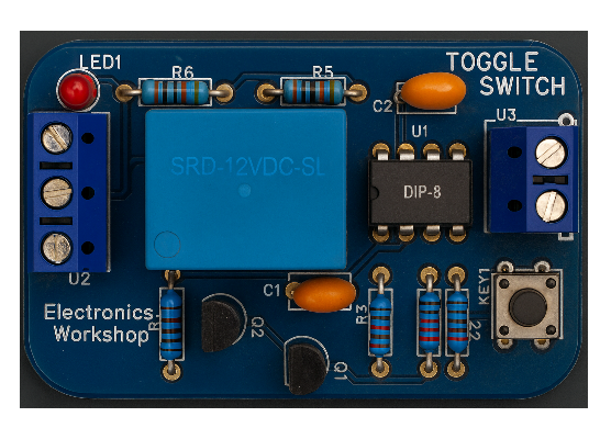
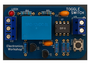
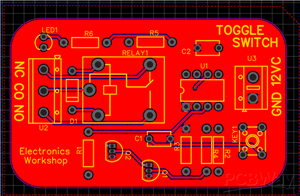
Below are some of my PCB’S manufactured by PCBWAY and I am fully satisfied by their Quality of service they provide.
Circuit Diagram

This circuit is a toggle switch with a timer using a 555 timer IC configured in monostable mode, designed to activate a relay for a fixed duration when a button is pressed. When the push-button is triggered, it sends a low pulse to the 555 timer’s trigger pin, causing the output (pin 3) to go high for a specific time determined by the resistor and capacitor connected to the timer (R3 and C3). This high output turns on an NPN transistor, which energizes the relay and can power an external device. An LED indicates the relay’s active state, and a flyback diode protects the transistor from voltage spikes. After the time period elapses, the timer automatically resets, turning off the relay and any connected load.
For Full Project:
https://electronicsworkshops.com/2025/03/26/toggle-switch-with-a-timer-using-the-555-timer-ic/
Section-by-Section Explanation
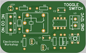
 Connection Diagram
1. Power Supply Section
VCC = 12V supplies the circuit.
Decoupling capacitors are added (near the power rail) for stability and noise filtering.
2. NE555 Timer IC (U1)
Operates in monostable mode.
Pin 2 (Trigger) is connected to a push-button (KEY1), which pulls the trigger pin LOW when pressed.
This initiates a one-shot pulse at pin 3 (Output).
3. Timing Components
R3 and C3 set the timer duration: T=1.1×R3×C3T = 1.1 \times R3 \times C3T=1.1×R3×C3
When KEY1 is pressed, the capacitor C3 charges and the output at pin 3 goes HIGH for a calculated time.
4. Output and Relay Control
Q2 (2N3904 NPN transistor) acts as a relay driver.
When pin 3 of the 555 is HIGH, it turns ON Q2, allowing current through the RELAY1 coil.
A flyback diode (D2 – 1N4007) across the relay protects the transistor from voltage spikes.
5. Indicator LEDs
LED1 (Green) shows relay status (ON when output is active).
Connected with resistor R6 to limit current.
LED2 at the output side shows power status or may be used for load indication.
6. Relay Output (J2)
The relay’s Normally Open (NO) and Common (COM) terminals are connected to an output terminal block.
This can switch external AC or DC loads like lamps, motors, etc.
Working Principle
Initially, the circuit is OFF.
When you press KEY1, pin 2 of the 555 is pulled LOW → triggers output HIGH.
Pin 3 remains HIGH for a duration set by R3 and C3.
During this time, Q2 turns ON → energizes the relay → turns ON external load.
After the time expires, pin 3 goes LOW → relay turns OFF automatically.
Applications
Automatic light or fan OFF after a fixed time
Delay timer for appliances
Door lock timer
Temporary load activation
Conclusion
In conclusion, this 555 timer-based toggle switch with timer circuit provides a simple yet effective solution for activating a device for a predetermined time using a single push-button. It combines the reliability of the NE555 timer in monostable mode with a transistor-driven relay to control external loads safely and automatically. The circuit is ideal for applications that require temporary activation, such as timed lighting, fans, or security systems, and demonstrates the practical use of basic electronic components in automation and control tasks.
For Full Project:
https://electronicsworkshops.com/2025/03/26/toggle-switch-with-a-timer-using-the-555-timer-ic/
Toggle switch with a timer using the 555 timer IC
*PCBWay community is a sharing platform. We are not responsible for any design issues and parameter issues (board thickness, surface finish, etc.) you choose.


Raspberry Pi 5 7 Inch Touch Screen IPS 1024x600 HD LCD HDMI-compatible Display for RPI 4B 3B+ OPI 5 AIDA64 PC Secondary Screen(Without Speaker)
BUY NOW


- Comments(0)
- Likes(1)
More by Rabin Poudel
-
 Automatic Water Pump Control System Using ESP-12F
IntroductionWater scarcity and wastage are major challenges in residential, agricultural, and indust...
Automatic Water Pump Control System Using ESP-12F
IntroductionWater scarcity and wastage are major challenges in residential, agricultural, and indust...
-
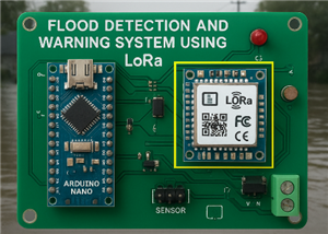 Flood Detection and warning system using LORA and Arduino
IntroductionFloods are one of the most devastating natural disasters, causing immense damage to life...
Flood Detection and warning system using LORA and Arduino
IntroductionFloods are one of the most devastating natural disasters, causing immense damage to life...
-
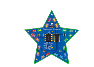 DIY LED Decoration Tiny Star PCB Project
IntroductionThe Tiny Star PCB is a small and fun DIY electronics project that is perfect for hobbyis...
DIY LED Decoration Tiny Star PCB Project
IntroductionThe Tiny Star PCB is a small and fun DIY electronics project that is perfect for hobbyis...
-
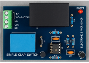 Simple and Cheap Clap Switch Circuit
IntroductionThe Simple and Cheap Clap Switch Circuit is a practical and fun DIY electronics project ...
Simple and Cheap Clap Switch Circuit
IntroductionThe Simple and Cheap Clap Switch Circuit is a practical and fun DIY electronics project ...
-
 Arduino-based Mist Maker and Hand Dryer
IntroductionIn today’s world, automation and hygiene have become essential, especially in public pla...
Arduino-based Mist Maker and Hand Dryer
IntroductionIn today’s world, automation and hygiene have become essential, especially in public pla...
-
 MPL3115A2 Barometric Pressure, Altitude, and Temperature Sensor
IntroductionThe MPL3115A2 is a highly accurate, low-power digital barometric pressure sensor from NX...
MPL3115A2 Barometric Pressure, Altitude, and Temperature Sensor
IntroductionThe MPL3115A2 is a highly accurate, low-power digital barometric pressure sensor from NX...
-
 E-Speaker Using ESP32
IntroductionThe E-Speaker is a smart, portable, and versatile audio system built using the ESP32 mic...
E-Speaker Using ESP32
IntroductionThe E-Speaker is a smart, portable, and versatile audio system built using the ESP32 mic...
-
 Heart Rate Monitor Circuit Using Photoplethysmography (PPG)
IntroductionHeart rate is a vital physiological parameter that reflects the health and fitness of an...
Heart Rate Monitor Circuit Using Photoplethysmography (PPG)
IntroductionHeart rate is a vital physiological parameter that reflects the health and fitness of an...
-
 Automated Greenhouse Control System using ESP32
IntroductionAn automated greenhouse control system leverages technology to optimize plant growth con...
Automated Greenhouse Control System using ESP32
IntroductionAn automated greenhouse control system leverages technology to optimize plant growth con...
-
 STD CH330N USB to Serial Converter 5V
IntroductionThe CH330N is a versatile USB-to-serial converter chip that simplifies interfacing betwe...
STD CH330N USB to Serial Converter 5V
IntroductionThe CH330N is a versatile USB-to-serial converter chip that simplifies interfacing betwe...
-
 KY-032 Obstacle avoidance sensor module
IntroductionIntroduction to Obstacle Avoidance SensorsObstacle avoidance sensors are essential compo...
KY-032 Obstacle avoidance sensor module
IntroductionIntroduction to Obstacle Avoidance SensorsObstacle avoidance sensors are essential compo...
-
 BC547 BASED WATER LEVEL INDICATOR
IntroductionA water level indicator using a BC547 transistor is a simple and effective electronic pr...
BC547 BASED WATER LEVEL INDICATOR
IntroductionA water level indicator using a BC547 transistor is a simple and effective electronic pr...
-
 How to Design Own Arduino Wifi shield PCB
OverviewArduino wifi shield connects the Arduino with a wifi chip through the serial communication p...
How to Design Own Arduino Wifi shield PCB
OverviewArduino wifi shield connects the Arduino with a wifi chip through the serial communication p...
-
 DIY Air Quality Tester
OverviewIn this project “DIY Air Quality Tester” we use Node MCU microcontroller and air quality sen...
DIY Air Quality Tester
OverviewIn this project “DIY Air Quality Tester” we use Node MCU microcontroller and air quality sen...
-
 Digital Clock Using Arduino
OverviewIn this project, “Digital clock using Arduino” we will make a PCB board for digital clock an...
Digital Clock Using Arduino
OverviewIn this project, “Digital clock using Arduino” we will make a PCB board for digital clock an...
-
 Bluetooth Controlled car using Arduino
OverviewA Bluetooth Controlled Car Using Arduino is a fascinating DIY project that involves building...
Bluetooth Controlled car using Arduino
OverviewA Bluetooth Controlled Car Using Arduino is a fascinating DIY project that involves building...
-
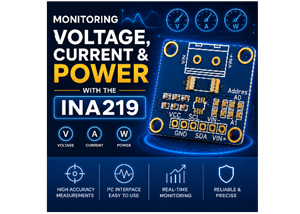 Monitoring Voltage, Current & Power with the INA219
IntroductionIf you’ve ever wanted to know exactly how much current your circuit is pulling, how much...
Monitoring Voltage, Current & Power with the INA219
IntroductionIf you’ve ever wanted to know exactly how much current your circuit is pulling, how much...
-
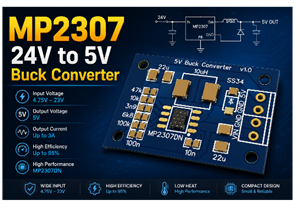 MP2307 5V to 24V Buck Converter
IntroductionIf you've ever needed to step down a higher DC voltage say, from a 12V or 24V source dow...
MP2307 5V to 24V Buck Converter
IntroductionIf you've ever needed to step down a higher DC voltage say, from a 12V or 24V source dow...
-
Programmable Mist Maker - XIAO / QT PY Extension
619 1 0 -
RadioHAT - Raspberry Pi radio development platform
487 0 1 -
-
-
-
-
ARPS-2 – Arduino-Compatible Robot Project Shield for Arduino UNO
3003 0 6 -
A Compact Charging Breakout Board For Waveshare ESP32-C3
3606 3 8 -
AI-driven LoRa & LLM-enabled Kiosk & Food Delivery System
3863 2 2


