


Digital Clock Using Arduino
Overview
In this project, “Digital clock using Arduino” we will make a PCB board for digital clock and program our Arduino so that it displays a time in seven segment display.
FOR FULL PROJECT
https://electronicsworkshops.com/2023/10/29/digital-clock-using-arduino/
Introduction
Creating a digital clock using an Arduino is a popular project that combines electronics, programming, and timekeeping. Such a clock displays the current time in a digital format, making it a useful and practical device. In this introduction, we’ll explore the fundamental concepts and components involved in building a digital clock using an Arduino.
Working Principle
The working principle of a digital clock using Arduino involves a combination of hardware components, such as the Arduino board and RTC module, and software programming to accurately track time and display it on a digital display. Here's how it works:
Real-Time Clock (RTC) Module:
The heart of the digital clock's timekeeping accuracy is the RTC module. It contains a real-time clock chip (e.g., DS1307, DS3231) that keeps track of the current time and date.
The RTC module typically has its own battery backup, which allows it to continue tracking time even when the main power to the Arduino is disconnected.
Arduino Microcontroller:
The Arduino serves as the controller and interface for the digital clock.
It communicates with the RTC module to request the current time and date information.
Programming:
The Arduino is programmed to perform the following tasks:
Initialize the RTC module: The code sets up the communication with the RTC module, configuring it to maintain and retrieve time and date information.
Request time data: The Arduino periodically sends a request to the RTC module to fetch the current time.
Process time data: The retrieved time data is processed by the Arduino to separate hours, minutes, and seconds. The date information can also be extracted if needed.
Display time: The Arduino code formats the time data and sends it to the digital display for visual presentation. The code may include formatting options like leading zeros, AM/PM indicators, or date display.
Update the display: The digital display is updated at regular intervals, typically once per second, to show the most current time.
Digital Display:
The digital clock uses a display (e.g., 7-segment display, OLED, TFT) to visually represent the time. The choice of display can vary, with different displays offering varying levels of customization and clarity.
Power Source:
The clock can be powered by a USB connection, a battery, or an external power supply.
The RTC module's battery backup ensures that time information is maintained even during power interruptions.
Enhanced Features (Optional):
Depending on the project's complexity, you can add features like alarm settings, date display, temperature and humidity monitoring, and different display options.
User Interaction (Optional):
Some digital clocks using Arduino can include buttons or other user interface elements to adjust settings, set alarms, or switch display modes.
The digital clock operates by reading the time from the RTC module at regular intervals, processing this information through Arduino code, and updating the digital display to show the current time. The RTC module's battery backup ensures that the clock continues to keep time accurately, even when power is temporarily interrupted.
This combination of precise timekeeping with an RTC module, Arduino's processing capabilities, and display technology allows you to create a functional and accurate digital clock that can be customized to meet various needs and preferences.
Working Steps
Connect the RTC Module: Wire the RTC module to the Arduino. Typically, you connect the SDA and SCL pins of the RTC module to the corresponding pins on the Arduino. You'll also connect power and ground.
Install Libraries: Utilize Arduino libraries to interface with the RTC module and your chosen display. Libraries like "RTClib" are commonly used for RTC modules, and there are display-specific libraries for different display types.
Write Arduino Code: Develop Arduino code that initializes the RTC module, retrieves the time, and displays it on the chosen display. You can customize the code to format the time, include features like date display and alarms, and control the display's appearance.
Upload Code: Use the Arduino Integrated Development Environment (IDE) to upload your code to the Arduino board.
Power the Clock: Connect your Arduino board to a power source (USB, battery, or an external power supply) to make the digital clock functional.
Enhance Features: As you gain experience, consider adding additional features to your digital clock, such as alarms, date display, different time formats, or the integration of other sensors like temperature and humidity sensors.
Schematic Diagram
 circuit of Digital clock using Arduino
FOR FULL PROJECT
https://electronicsworkshops.com/2023/10/29/digital-clock-using-arduino/
Digital Clock Using Arduino
Project images are for reference only. Actual production is based on the manufacturing files on the project page.
Please review the designer's notes (e.g., PCB thickness) and select the appropriate options.
PCBWay is not responsible
for issues caused by unsuitable parameter selections.
For more important ordering information, please refer to
Read More


Raspberry Pi 5 7 Inch Touch Screen IPS 1024x600 HD LCD HDMI-compatible Display for RPI 4B 3B+ OPI 5 AIDA64 PC Secondary Screen(Without Speaker)
BUY NOW

- Comments(0)
- Likes(3)
More by Rabin Poudel
-
 Automatic Water Pump Control System Using ESP-12F
IntroductionWater scarcity and wastage are major challenges in residential, agricultural, and indust...
Automatic Water Pump Control System Using ESP-12F
IntroductionWater scarcity and wastage are major challenges in residential, agricultural, and indust...
-
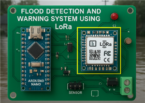 Flood Detection and warning system using LORA and Arduino
IntroductionFloods are one of the most devastating natural disasters, causing immense damage to life...
Flood Detection and warning system using LORA and Arduino
IntroductionFloods are one of the most devastating natural disasters, causing immense damage to life...
-
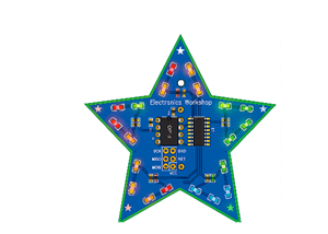 DIY LED Decoration Tiny Star PCB Project
IntroductionThe Tiny Star PCB is a small and fun DIY electronics project that is perfect for hobbyis...
DIY LED Decoration Tiny Star PCB Project
IntroductionThe Tiny Star PCB is a small and fun DIY electronics project that is perfect for hobbyis...
-
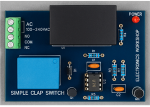 Simple and Cheap Clap Switch Circuit
IntroductionThe Simple and Cheap Clap Switch Circuit is a practical and fun DIY electronics project ...
Simple and Cheap Clap Switch Circuit
IntroductionThe Simple and Cheap Clap Switch Circuit is a practical and fun DIY electronics project ...
-
 Arduino-based Mist Maker and Hand Dryer
IntroductionIn today’s world, automation and hygiene have become essential, especially in public pla...
Arduino-based Mist Maker and Hand Dryer
IntroductionIn today’s world, automation and hygiene have become essential, especially in public pla...
-
 MPL3115A2 Barometric Pressure, Altitude, and Temperature Sensor
IntroductionThe MPL3115A2 is a highly accurate, low-power digital barometric pressure sensor from NX...
MPL3115A2 Barometric Pressure, Altitude, and Temperature Sensor
IntroductionThe MPL3115A2 is a highly accurate, low-power digital barometric pressure sensor from NX...
-
 E-Speaker Using ESP32
IntroductionThe E-Speaker is a smart, portable, and versatile audio system built using the ESP32 mic...
E-Speaker Using ESP32
IntroductionThe E-Speaker is a smart, portable, and versatile audio system built using the ESP32 mic...
-
 Heart Rate Monitor Circuit Using Photoplethysmography (PPG)
IntroductionHeart rate is a vital physiological parameter that reflects the health and fitness of an...
Heart Rate Monitor Circuit Using Photoplethysmography (PPG)
IntroductionHeart rate is a vital physiological parameter that reflects the health and fitness of an...
-
 Automated Greenhouse Control System using ESP32
IntroductionAn automated greenhouse control system leverages technology to optimize plant growth con...
Automated Greenhouse Control System using ESP32
IntroductionAn automated greenhouse control system leverages technology to optimize plant growth con...
-
 STD CH330N USB to Serial Converter 5V
IntroductionThe CH330N is a versatile USB-to-serial converter chip that simplifies interfacing betwe...
STD CH330N USB to Serial Converter 5V
IntroductionThe CH330N is a versatile USB-to-serial converter chip that simplifies interfacing betwe...
-
 KY-032 Obstacle avoidance sensor module
IntroductionIntroduction to Obstacle Avoidance SensorsObstacle avoidance sensors are essential compo...
KY-032 Obstacle avoidance sensor module
IntroductionIntroduction to Obstacle Avoidance SensorsObstacle avoidance sensors are essential compo...
-
 BC547 BASED WATER LEVEL INDICATOR
IntroductionA water level indicator using a BC547 transistor is a simple and effective electronic pr...
BC547 BASED WATER LEVEL INDICATOR
IntroductionA water level indicator using a BC547 transistor is a simple and effective electronic pr...
-
 How to Design Own Arduino Wifi shield PCB
OverviewArduino wifi shield connects the Arduino with a wifi chip through the serial communication p...
How to Design Own Arduino Wifi shield PCB
OverviewArduino wifi shield connects the Arduino with a wifi chip through the serial communication p...
-
 DIY Air Quality Tester
OverviewIn this project “DIY Air Quality Tester” we use Node MCU microcontroller and air quality sen...
DIY Air Quality Tester
OverviewIn this project “DIY Air Quality Tester” we use Node MCU microcontroller and air quality sen...
-
 Digital Clock Using Arduino
OverviewIn this project, “Digital clock using Arduino” we will make a PCB board for digital clock an...
Digital Clock Using Arduino
OverviewIn this project, “Digital clock using Arduino” we will make a PCB board for digital clock an...
-
 Bluetooth Controlled car using Arduino
OverviewA Bluetooth Controlled Car Using Arduino is a fascinating DIY project that involves building...
Bluetooth Controlled car using Arduino
OverviewA Bluetooth Controlled Car Using Arduino is a fascinating DIY project that involves building...
-
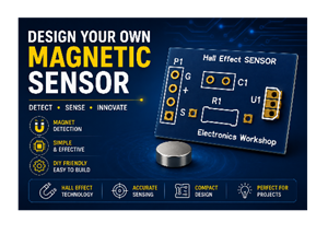 Design a Magnetic Sensor Using S411A
IntroductionMagnetic sensors are widely used in modern electronic systems for detecting the presence...
Design a Magnetic Sensor Using S411A
IntroductionMagnetic sensors are widely used in modern electronic systems for detecting the presence...
-
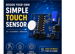 Design Simple Touch Sensor Using LM324
IntroductionTouch sensors have become an essential part of modern electronic devices, replacing trad...
Design Simple Touch Sensor Using LM324
IntroductionTouch sensors have become an essential part of modern electronic devices, replacing trad...
-
Programmable Mist Maker - XIAO / QT PY Extension
1062 2 1 -
RadioHAT - Raspberry Pi radio development platform
874 0 2 -
-
-
-
-
ARPS-2 – Arduino-Compatible Robot Project Shield for Arduino UNO
3327 0 6 -
A Compact Charging Breakout Board For Waveshare ESP32-C3
3934 3 8 -
AI-driven LoRa & LLM-enabled Kiosk & Food Delivery System
4323 2 2


