


I2C OLED Display with Arduino For Beginner
Overview
This article I2C OLED Display with Arduino demonstrates how to use the Arduino and the SSD1306 0.96-inch I2C OLED display. We’ll show you some features of the OLED display, how to connect it to the Arduino board, and how to write text, draw shapes and display bitmap images.
Introduction
In the realm of DIY electronics, one of the most fascinating combinations is the Arduino microcontroller and OLED displays. In this beginner’s guide, we will delve into the world of I2C OLED displays and explore how to integrate them with an Arduino. By the end of this article, you will have the knowledge and confidence to embark on exciting projects of your own.
What is an OLED Display?
An OLED (Organic Light-Emitting Diode) display is a cutting-edge technology that emits light when an electric current is applied. Unlike traditional LCDs, OLEDs do not require a backlight, resulting in vibrant colors, high contrast, and excellent visibility, even in low-light conditions. These displays are widely used in smartphones, smartwatches, and numerous other electronic devices.
 OLED Display
What is I2C Communication?
Inter-Integrated Circuit (I2C) is a simple and widely-used serial communication protocol that enables multiple devices to communicate over just two wires: SDA (Serial Data) and SCL (Serial Clock). I2C is particularly useful for connecting peripherals, like OLED displays, to microcontrollers such as Arduino, allowing seamless data exchange between devices.
Working Principle Of I2C OLED Display with Arduino
The I2C OLED display with Arduino works by establishing communication between the Arduino and the display using the I2C protocol. The Arduino sends commands and data to the display, which processes and controls the individual pixels on the OLED screen to display the desired content. The Arduino can continuously update the display, making it suitable for various applications, from basic text displays to more interactive and dynamic projects.
Circuit Diagram
 Circuit Diagram Of I2C OLED Display with Arduino
Connect the GND pin of the OLED display to any GND pin on the Arduino board.
Connect the VCC pin of the OLED display to the 5V pin on the Arduino board.
Connect the SDA pin of the OLED display to the A4 (Analog 4) pin on the Arduino board.
Connect the SCL pin of the OLED display to the A5 (Analog 5) pin on the Arduino board
FOR FULL PROJECT GO TO BELOW LINK :

I2C OLED Display with Arduino For Beginner
Project images are for reference only. Actual production is based on the manufacturing files on the project page.
Please review the designer's notes (e.g., PCB thickness) and select the appropriate options.
PCBWay is not responsible
for issues caused by unsuitable parameter selections.
For more important ordering information, please refer to
Read More


Raspberry Pi 5 7 Inch Touch Screen IPS 1024x600 HD LCD HDMI-compatible Display for RPI 4B 3B+ OPI 5 AIDA64 PC Secondary Screen(Without Speaker)
BUY NOW

- Comments(0)
- Likes(0)
More by Rabin Poudel
-
 Automatic Water Pump Control System Using ESP-12F
IntroductionWater scarcity and wastage are major challenges in residential, agricultural, and indust...
Automatic Water Pump Control System Using ESP-12F
IntroductionWater scarcity and wastage are major challenges in residential, agricultural, and indust...
-
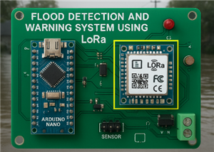 Flood Detection and warning system using LORA and Arduino
IntroductionFloods are one of the most devastating natural disasters, causing immense damage to life...
Flood Detection and warning system using LORA and Arduino
IntroductionFloods are one of the most devastating natural disasters, causing immense damage to life...
-
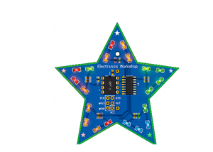 DIY LED Decoration Tiny Star PCB Project
IntroductionThe Tiny Star PCB is a small and fun DIY electronics project that is perfect for hobbyis...
DIY LED Decoration Tiny Star PCB Project
IntroductionThe Tiny Star PCB is a small and fun DIY electronics project that is perfect for hobbyis...
-
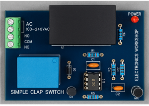 Simple and Cheap Clap Switch Circuit
IntroductionThe Simple and Cheap Clap Switch Circuit is a practical and fun DIY electronics project ...
Simple and Cheap Clap Switch Circuit
IntroductionThe Simple and Cheap Clap Switch Circuit is a practical and fun DIY electronics project ...
-
 Arduino-based Mist Maker and Hand Dryer
IntroductionIn today’s world, automation and hygiene have become essential, especially in public pla...
Arduino-based Mist Maker and Hand Dryer
IntroductionIn today’s world, automation and hygiene have become essential, especially in public pla...
-
 MPL3115A2 Barometric Pressure, Altitude, and Temperature Sensor
IntroductionThe MPL3115A2 is a highly accurate, low-power digital barometric pressure sensor from NX...
MPL3115A2 Barometric Pressure, Altitude, and Temperature Sensor
IntroductionThe MPL3115A2 is a highly accurate, low-power digital barometric pressure sensor from NX...
-
 E-Speaker Using ESP32
IntroductionThe E-Speaker is a smart, portable, and versatile audio system built using the ESP32 mic...
E-Speaker Using ESP32
IntroductionThe E-Speaker is a smart, portable, and versatile audio system built using the ESP32 mic...
-
 Heart Rate Monitor Circuit Using Photoplethysmography (PPG)
IntroductionHeart rate is a vital physiological parameter that reflects the health and fitness of an...
Heart Rate Monitor Circuit Using Photoplethysmography (PPG)
IntroductionHeart rate is a vital physiological parameter that reflects the health and fitness of an...
-
 Automated Greenhouse Control System using ESP32
IntroductionAn automated greenhouse control system leverages technology to optimize plant growth con...
Automated Greenhouse Control System using ESP32
IntroductionAn automated greenhouse control system leverages technology to optimize plant growth con...
-
 STD CH330N USB to Serial Converter 5V
IntroductionThe CH330N is a versatile USB-to-serial converter chip that simplifies interfacing betwe...
STD CH330N USB to Serial Converter 5V
IntroductionThe CH330N is a versatile USB-to-serial converter chip that simplifies interfacing betwe...
-
 KY-032 Obstacle avoidance sensor module
IntroductionIntroduction to Obstacle Avoidance SensorsObstacle avoidance sensors are essential compo...
KY-032 Obstacle avoidance sensor module
IntroductionIntroduction to Obstacle Avoidance SensorsObstacle avoidance sensors are essential compo...
-
 BC547 BASED WATER LEVEL INDICATOR
IntroductionA water level indicator using a BC547 transistor is a simple and effective electronic pr...
BC547 BASED WATER LEVEL INDICATOR
IntroductionA water level indicator using a BC547 transistor is a simple and effective electronic pr...
-
 How to Design Own Arduino Wifi shield PCB
OverviewArduino wifi shield connects the Arduino with a wifi chip through the serial communication p...
How to Design Own Arduino Wifi shield PCB
OverviewArduino wifi shield connects the Arduino with a wifi chip through the serial communication p...
-
 DIY Air Quality Tester
OverviewIn this project “DIY Air Quality Tester” we use Node MCU microcontroller and air quality sen...
DIY Air Quality Tester
OverviewIn this project “DIY Air Quality Tester” we use Node MCU microcontroller and air quality sen...
-
 Digital Clock Using Arduino
OverviewIn this project, “Digital clock using Arduino” we will make a PCB board for digital clock an...
Digital Clock Using Arduino
OverviewIn this project, “Digital clock using Arduino” we will make a PCB board for digital clock an...
-
 Bluetooth Controlled car using Arduino
OverviewA Bluetooth Controlled Car Using Arduino is a fascinating DIY project that involves building...
Bluetooth Controlled car using Arduino
OverviewA Bluetooth Controlled Car Using Arduino is a fascinating DIY project that involves building...
-
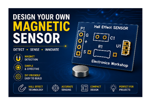 Design a Magnetic Sensor Using S411A
IntroductionMagnetic sensors are widely used in modern electronic systems for detecting the presence...
Design a Magnetic Sensor Using S411A
IntroductionMagnetic sensors are widely used in modern electronic systems for detecting the presence...
-
 Design Simple Touch Sensor Using LM324
IntroductionTouch sensors have become an essential part of modern electronic devices, replacing trad...
Design Simple Touch Sensor Using LM324
IntroductionTouch sensors have become an essential part of modern electronic devices, replacing trad...
-
Programmable Mist Maker - XIAO / QT PY Extension
1180 2 1 -
RadioHAT - Raspberry Pi radio development platform
984 0 2 -
-
-
-
-
ARPS-2 – Arduino-Compatible Robot Project Shield for Arduino UNO
3399 0 6 -
A Compact Charging Breakout Board For Waveshare ESP32-C3
4024 3 8 -
AI-driven LoRa & LLM-enabled Kiosk & Food Delivery System
4417 2 2


