


Smart Electrical Parameter Monitoring , Fault Alert and control System
Introduction
The Smart Electrical Parameter Monitoring, Fault Alert, and Control System is an embedded solution designed to monitor critical electrical parameters of a single-phase AC system, detect faults in real time, and take automatic protective actions. Traditional electrical systems rely heavily on manual inspection and basic protection devices, which may not provide early warnings or detailed system status. This project overcomes those limitations by combining isolated sensing circuits, intelligent processing using an ESP32 microcontroller, and automated control mechanisms, ensuring higher safety, reliability, and efficiency.
For Full Project:
https://electronicsworkshops.com/smart-electrical-parameter-monitoring-and-fault-alert-system/

Objectives
To continuously monitor AC voltage, phase presence, and load current
To detect electrical faults such as overvoltage, undervoltage, phase failure, and overcurrent
To provide real-time fault alerts and system status
To automatically control relays and cooling fans for protection and thermal management
To ensure electrical isolation and safety between high-voltage AC and low-voltage electronics
System Overview
The system works by first taking a single-phase AC input, from which voltage, phase, and load current are safely sensed using isolated potential and current transformers, then conditioned through filtering and amplifier circuits to produce low-voltage analog signals. These signals are fed into an ESP32 microcontroller, which continuously processes the data, compares it with predefined safe limits, and determines the system’s operating condition. If a fault such as overvoltage, undervoltage, phase loss, or overcurrent is detected, the controller immediately triggers alerts and control actions, including switching a relay to disconnect the load and activating cooling fans when required. A regulated 12 V to 5 V and 3.3 V power supply ensures stable operation of all electronics, while communication interfaces allow system expansion, making the overall flow a closed-loop process of sensing → decision-making → protection → control for safe and intelligent electrical system operation.
Fault Detection and Alert Logic
The system detects multiple fault conditions, including:
Overvoltage / Undervoltage – protects connected equipment from unstable supply
Phase Loss – prevents single-phasing damage
Overcurrent / Overload – avoids overheating and component failure
When a fault is detected:
A fault flag is generated internally
Control signals are immediately sent to disconnect or limit the load
Alerts can be transmitted to displays, indicators, or external systems
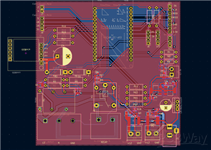
Circuit Diagram
This circuit is a single-phase AC monitoring and control module that measures AC voltage, phase presence, and load current, then uses that information to drive a relay and cooling fans safely with electrical isolation. The AC input (L, N) is stepped down and isolated using a potential transformer, and the reduced AC signal is conditioned by LM321 op-amp comparator circuits to generate logic-level signals labeled Voltage1 and Phase1, which indicate mains voltage availability and phase detection for a microcontroller. Current measurement is done through a current transformer (CT) at connector J1; its signal is rectified, filtered, and amplified by another LM321, producing a proportional Current output. On the control side, logic signals (RELAY_CONTROL, fan_control_1, fan_control_2) drive NPN transistors (2SD400A) that switch a relay and 12 V DC fans, with flyback diodes (1N4007) protecting against inductive spikes and polyfuses providing overcurrent protection. Overall, the circuit safely interfaces high-voltage AC with low-voltage electronics, enabling real-time monitoring and protective control of electrical loads—well suited for energy monitoring, protection systems, or EV/industrial applications.

A 12 V DC input from a barrel jack is stepped down to 5 V using a linear regulator and further regulated to 3.3 V for the ESP32, with diodes and capacitors providing reverse-polarity protection and supply filtering. The board exposes I²C communication via a dedicated connector with proper pull-up resistors for adding external sensors or peripherals, includes headers for SPI/flash/programming, and provides a connector for a temperature sensor, making this section the central processing, power-management, and communication hub that links all measurement, protection, and control functions together.

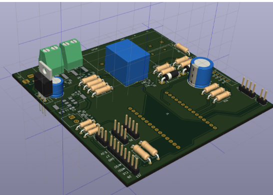
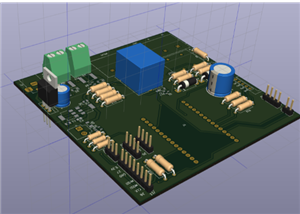
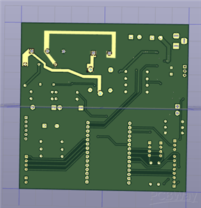
PCB


3D


Applications
Industrial electrical panels
EV charging stations and service equipment
Energy monitoring and management systems
Smart protection devices and automation systems
Commercial and residential electrical safety systems
For Full Project:
https://electronicsworkshops.com/smart-electrical-parameter-monitoring-and-fault-alert-system/
Conclusion
The Smart Electrical Parameter Monitoring, Fault Alert, and Control System provides an intelligent, reliable, and safe solution for modern electrical systems. By integrating real-time monitoring, automated fault detection, and protective control, the project significantly reduces the risk of equipment damage, improves operational safety, and supports predictive maintenance. Its modular design and expandability make it suitable for a wide range of industrial and smart energy applications.
Smart Electrical Parameter Monitoring , Fault Alert and control System
Project images are for reference only. Actual production is based on the manufacturing files on the project page.
Please review the designer's notes (e.g., PCB thickness) and select the appropriate options.
PCBWay is not responsible
for issues caused by unsuitable parameter selections.
For more important ordering information, please refer to
Read More


Raspberry Pi 5 7 Inch Touch Screen IPS 1024x600 HD LCD HDMI-compatible Display for RPI 4B 3B+ OPI 5 AIDA64 PC Secondary Screen(Without Speaker)
BUY NOW

- Comments(0)
- Likes(0)
More by Rabin Poudel
-
 Automatic Water Pump Control System Using ESP-12F
IntroductionWater scarcity and wastage are major challenges in residential, agricultural, and indust...
Automatic Water Pump Control System Using ESP-12F
IntroductionWater scarcity and wastage are major challenges in residential, agricultural, and indust...
-
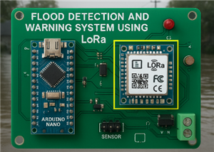 Flood Detection and warning system using LORA and Arduino
IntroductionFloods are one of the most devastating natural disasters, causing immense damage to life...
Flood Detection and warning system using LORA and Arduino
IntroductionFloods are one of the most devastating natural disasters, causing immense damage to life...
-
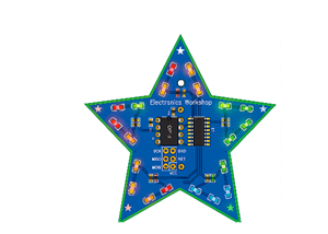 DIY LED Decoration Tiny Star PCB Project
IntroductionThe Tiny Star PCB is a small and fun DIY electronics project that is perfect for hobbyis...
DIY LED Decoration Tiny Star PCB Project
IntroductionThe Tiny Star PCB is a small and fun DIY electronics project that is perfect for hobbyis...
-
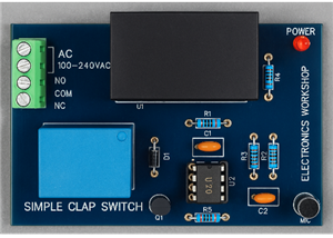 Simple and Cheap Clap Switch Circuit
IntroductionThe Simple and Cheap Clap Switch Circuit is a practical and fun DIY electronics project ...
Simple and Cheap Clap Switch Circuit
IntroductionThe Simple and Cheap Clap Switch Circuit is a practical and fun DIY electronics project ...
-
 Arduino-based Mist Maker and Hand Dryer
IntroductionIn today’s world, automation and hygiene have become essential, especially in public pla...
Arduino-based Mist Maker and Hand Dryer
IntroductionIn today’s world, automation and hygiene have become essential, especially in public pla...
-
 MPL3115A2 Barometric Pressure, Altitude, and Temperature Sensor
IntroductionThe MPL3115A2 is a highly accurate, low-power digital barometric pressure sensor from NX...
MPL3115A2 Barometric Pressure, Altitude, and Temperature Sensor
IntroductionThe MPL3115A2 is a highly accurate, low-power digital barometric pressure sensor from NX...
-
 E-Speaker Using ESP32
IntroductionThe E-Speaker is a smart, portable, and versatile audio system built using the ESP32 mic...
E-Speaker Using ESP32
IntroductionThe E-Speaker is a smart, portable, and versatile audio system built using the ESP32 mic...
-
 Heart Rate Monitor Circuit Using Photoplethysmography (PPG)
IntroductionHeart rate is a vital physiological parameter that reflects the health and fitness of an...
Heart Rate Monitor Circuit Using Photoplethysmography (PPG)
IntroductionHeart rate is a vital physiological parameter that reflects the health and fitness of an...
-
 Automated Greenhouse Control System using ESP32
IntroductionAn automated greenhouse control system leverages technology to optimize plant growth con...
Automated Greenhouse Control System using ESP32
IntroductionAn automated greenhouse control system leverages technology to optimize plant growth con...
-
 STD CH330N USB to Serial Converter 5V
IntroductionThe CH330N is a versatile USB-to-serial converter chip that simplifies interfacing betwe...
STD CH330N USB to Serial Converter 5V
IntroductionThe CH330N is a versatile USB-to-serial converter chip that simplifies interfacing betwe...
-
 KY-032 Obstacle avoidance sensor module
IntroductionIntroduction to Obstacle Avoidance SensorsObstacle avoidance sensors are essential compo...
KY-032 Obstacle avoidance sensor module
IntroductionIntroduction to Obstacle Avoidance SensorsObstacle avoidance sensors are essential compo...
-
 BC547 BASED WATER LEVEL INDICATOR
IntroductionA water level indicator using a BC547 transistor is a simple and effective electronic pr...
BC547 BASED WATER LEVEL INDICATOR
IntroductionA water level indicator using a BC547 transistor is a simple and effective electronic pr...
-
 How to Design Own Arduino Wifi shield PCB
OverviewArduino wifi shield connects the Arduino with a wifi chip through the serial communication p...
How to Design Own Arduino Wifi shield PCB
OverviewArduino wifi shield connects the Arduino with a wifi chip through the serial communication p...
-
 DIY Air Quality Tester
OverviewIn this project “DIY Air Quality Tester” we use Node MCU microcontroller and air quality sen...
DIY Air Quality Tester
OverviewIn this project “DIY Air Quality Tester” we use Node MCU microcontroller and air quality sen...
-
 Digital Clock Using Arduino
OverviewIn this project, “Digital clock using Arduino” we will make a PCB board for digital clock an...
Digital Clock Using Arduino
OverviewIn this project, “Digital clock using Arduino” we will make a PCB board for digital clock an...
-
 Bluetooth Controlled car using Arduino
OverviewA Bluetooth Controlled Car Using Arduino is a fascinating DIY project that involves building...
Bluetooth Controlled car using Arduino
OverviewA Bluetooth Controlled Car Using Arduino is a fascinating DIY project that involves building...
-
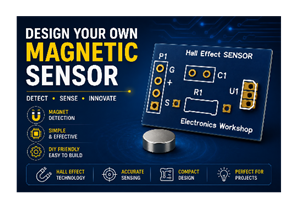 Design a Magnetic Sensor Using S411A
IntroductionMagnetic sensors are widely used in modern electronic systems for detecting the presence...
Design a Magnetic Sensor Using S411A
IntroductionMagnetic sensors are widely used in modern electronic systems for detecting the presence...
-
 Design Simple Touch Sensor Using LM324
IntroductionTouch sensors have become an essential part of modern electronic devices, replacing trad...
Design Simple Touch Sensor Using LM324
IntroductionTouch sensors have become an essential part of modern electronic devices, replacing trad...
-
Programmable Mist Maker - XIAO / QT PY Extension
1022 2 1 -
RadioHAT - Raspberry Pi radio development platform
828 0 2 -
-
-
-
-
ARPS-2 – Arduino-Compatible Robot Project Shield for Arduino UNO
3281 0 6 -
A Compact Charging Breakout Board For Waveshare ESP32-C3
3904 3 8 -
AI-driven LoRa & LLM-enabled Kiosk & Food Delivery System
4282 2 2


