


BC547 BASED WATER LEVEL INDICATOR
Introduction
A water level indicator using a BC547 transistor is a simple and effective electronic project that helps in monitoring the water level in a tank. The BC547 is a commonly used NPN transistor that can act as a switch in this application. Here’s how you can create a basic water level indicator using the BC547 transistor.
For Full Project:
https://electronicsworkshops.com/2024/05/30/bc547-based-water-level-indicator/
Components Needed
- BC547 Transistors (4 pieces)
- Resistors (4 pieces of 1kΩ)
- LEDs (4 pieces)
- Wires
- Battery or power supply (5V)
- Water container
Steps to Build the Circuit
Setup the Transistors and LEDs: Connect the emitter of the BC547 transistor (Q1) to ground (GND). The collector of the transistor is connected to one terminal of the LED (LED1). The other terminal of the LED is connected to a resistor (R1, 1kΩ), and the other end of the resistor is connected to +5V power supply.
Water Probes: Insert a probe (conductive material, such as a metal wire) into the water tank at the level where you want to monitor. This probe is connected to the base of the BC547 transistor.
Multiple Levels: Repeat the above setup for more water levels using additional BC547 transistors, resistors, and LEDs. Each level will have its own transistor, resistor, and LED.
Connect the Circuit: Connect all the components as per the circuit diagram. Ensure that the power supply, LEDs, resistors, and transistors are correctly connected.
How it Works
When the water level reaches the probe connected to the base of the transistor (Q1), it completes the circuit and allows current to flow from the collector to the emitter.
This flow of current will light up the LED1, indicating that the water has reached that level.
If the water level is below the probe, the transistor will remain off, and the LED will not light up.
Example for Multiple Levels
You can place multiple probes at different heights inside the water tank. For each probe, connect a BC547 transistor, resistor, and LED as described above. When the water reaches each probe, the corresponding LED will light up.
Testing the Circuit
Power Up: Connect the circuit to a 5V power supply.
Simulate Water Levels: Place the water container with probes at different levels.
Observe LEDs: As the water level rises and touches each probe, the corresponding LED should light up.
Conclusion
This simple BC547-based water level indicator can be used to effectively monitor water levels in a tank and give a visual indication through LEDs.
https://electronicsworkshops.com/2024/05/30/bc547-based-water-level-indicator/
BC547 BASED WATER LEVEL INDICATOR
*PCBWay community is a sharing platform. We are not responsible for any design issues and parameter issues (board thickness, surface finish, etc.) you choose.


Raspberry Pi 5 7 Inch Touch Screen IPS 1024x600 HD LCD HDMI-compatible Display for RPI 4B 3B+ OPI 5 AIDA64 PC Secondary Screen(Without Speaker)
BUY NOW


- Comments(0)
- Likes(2)
More by Rabin Poudel
-
 Automatic Water Pump Control System Using ESP-12F
IntroductionWater scarcity and wastage are major challenges in residential, agricultural, and indust...
Automatic Water Pump Control System Using ESP-12F
IntroductionWater scarcity and wastage are major challenges in residential, agricultural, and indust...
-
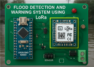 Flood Detection and warning system using LORA and Arduino
IntroductionFloods are one of the most devastating natural disasters, causing immense damage to life...
Flood Detection and warning system using LORA and Arduino
IntroductionFloods are one of the most devastating natural disasters, causing immense damage to life...
-
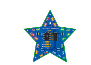 DIY LED Decoration Tiny Star PCB Project
IntroductionThe Tiny Star PCB is a small and fun DIY electronics project that is perfect for hobbyis...
DIY LED Decoration Tiny Star PCB Project
IntroductionThe Tiny Star PCB is a small and fun DIY electronics project that is perfect for hobbyis...
-
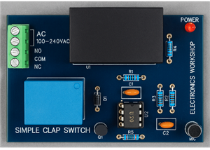 Simple and Cheap Clap Switch Circuit
IntroductionThe Simple and Cheap Clap Switch Circuit is a practical and fun DIY electronics project ...
Simple and Cheap Clap Switch Circuit
IntroductionThe Simple and Cheap Clap Switch Circuit is a practical and fun DIY electronics project ...
-
 Arduino-based Mist Maker and Hand Dryer
IntroductionIn today’s world, automation and hygiene have become essential, especially in public pla...
Arduino-based Mist Maker and Hand Dryer
IntroductionIn today’s world, automation and hygiene have become essential, especially in public pla...
-
 MPL3115A2 Barometric Pressure, Altitude, and Temperature Sensor
IntroductionThe MPL3115A2 is a highly accurate, low-power digital barometric pressure sensor from NX...
MPL3115A2 Barometric Pressure, Altitude, and Temperature Sensor
IntroductionThe MPL3115A2 is a highly accurate, low-power digital barometric pressure sensor from NX...
-
 E-Speaker Using ESP32
IntroductionThe E-Speaker is a smart, portable, and versatile audio system built using the ESP32 mic...
E-Speaker Using ESP32
IntroductionThe E-Speaker is a smart, portable, and versatile audio system built using the ESP32 mic...
-
 Heart Rate Monitor Circuit Using Photoplethysmography (PPG)
IntroductionHeart rate is a vital physiological parameter that reflects the health and fitness of an...
Heart Rate Monitor Circuit Using Photoplethysmography (PPG)
IntroductionHeart rate is a vital physiological parameter that reflects the health and fitness of an...
-
 Automated Greenhouse Control System using ESP32
IntroductionAn automated greenhouse control system leverages technology to optimize plant growth con...
Automated Greenhouse Control System using ESP32
IntroductionAn automated greenhouse control system leverages technology to optimize plant growth con...
-
 STD CH330N USB to Serial Converter 5V
IntroductionThe CH330N is a versatile USB-to-serial converter chip that simplifies interfacing betwe...
STD CH330N USB to Serial Converter 5V
IntroductionThe CH330N is a versatile USB-to-serial converter chip that simplifies interfacing betwe...
-
 KY-032 Obstacle avoidance sensor module
IntroductionIntroduction to Obstacle Avoidance SensorsObstacle avoidance sensors are essential compo...
KY-032 Obstacle avoidance sensor module
IntroductionIntroduction to Obstacle Avoidance SensorsObstacle avoidance sensors are essential compo...
-
 BC547 BASED WATER LEVEL INDICATOR
IntroductionA water level indicator using a BC547 transistor is a simple and effective electronic pr...
BC547 BASED WATER LEVEL INDICATOR
IntroductionA water level indicator using a BC547 transistor is a simple and effective electronic pr...
-
 How to Design Own Arduino Wifi shield PCB
OverviewArduino wifi shield connects the Arduino with a wifi chip through the serial communication p...
How to Design Own Arduino Wifi shield PCB
OverviewArduino wifi shield connects the Arduino with a wifi chip through the serial communication p...
-
 DIY Air Quality Tester
OverviewIn this project “DIY Air Quality Tester” we use Node MCU microcontroller and air quality sen...
DIY Air Quality Tester
OverviewIn this project “DIY Air Quality Tester” we use Node MCU microcontroller and air quality sen...
-
 Digital Clock Using Arduino
OverviewIn this project, “Digital clock using Arduino” we will make a PCB board for digital clock an...
Digital Clock Using Arduino
OverviewIn this project, “Digital clock using Arduino” we will make a PCB board for digital clock an...
-
 Bluetooth Controlled car using Arduino
OverviewA Bluetooth Controlled Car Using Arduino is a fascinating DIY project that involves building...
Bluetooth Controlled car using Arduino
OverviewA Bluetooth Controlled Car Using Arduino is a fascinating DIY project that involves building...
-
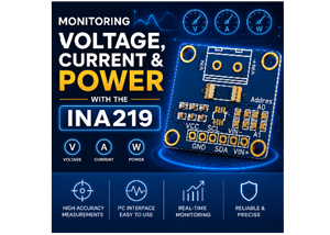 Monitoring Voltage, Current & Power with the INA219
IntroductionIf you’ve ever wanted to know exactly how much current your circuit is pulling, how much...
Monitoring Voltage, Current & Power with the INA219
IntroductionIf you’ve ever wanted to know exactly how much current your circuit is pulling, how much...
-
 MP2307 5V to 24V Buck Converter
IntroductionIf you've ever needed to step down a higher DC voltage say, from a 12V or 24V source dow...
MP2307 5V to 24V Buck Converter
IntroductionIf you've ever needed to step down a higher DC voltage say, from a 12V or 24V source dow...
-
Programmable Mist Maker - XIAO / QT PY Extension
241 0 0 -
RadioHAT - Raspberry Pi radio development platform
263 0 1 -
-
-
-
-
ARPS-2 – Arduino-Compatible Robot Project Shield for Arduino UNO
2821 0 6 -
A Compact Charging Breakout Board For Waveshare ESP32-C3
3326 3 8 -
AI-driven LoRa & LLM-enabled Kiosk & Food Delivery System
3619 2 2


