


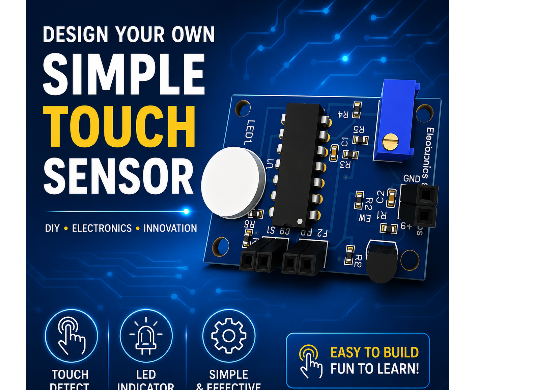
Design Simple Touch Sensor Using LM324
Introduction
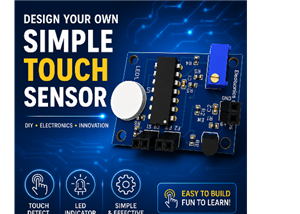
Touch sensors have become an essential part of modern electronic devices, replacing traditional mechanical switches in many applications. In this project, we will design a simple touch sensor using the LM324 operational amplifier. The circuit is inexpensive, easy to build, and perfect for beginners learning analog electronics and PCB design.
Whether you're an electronics student, hobbyist, or DIY maker, this project helps you understand how touch sensing works using an operational amplifier instead of dedicated touch sensor ICs.
For Full Project:
https://electronicsworkshops.com/design-simple-touch-sensor-using-lm324/
For Best Electronics Calculator:
https://numericalcalculator.com/
What is a Touch Sensor?
A touch sensor is an electronic circuit that detects the presence of a human finger by sensing tiny electrical changes. Unlike push buttons, touch sensors require no mechanical movement, making them more reliable and longer lasting.
Touch sensors are commonly found in:
- Home automation systems
- LED touch lamps
- Smart switches
- Consumer electronics
- Industrial control panels
- DIY electronic projects
LM324 Pin Layout
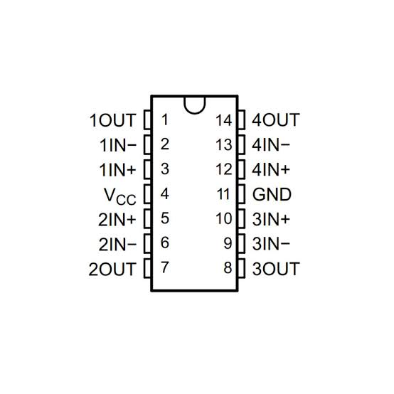
The LM324 is a 14-pin quad operational amplifier (Op-Amp) IC that contains four independent op-amps within a single package, making it ideal for a wide range of analog applications such as amplifiers, comparators, filters, oscillators, and sensor circuits. The IC is powered through Pin 4 (VCC) and Pin 11 (GND), while the remaining pins are divided into four identical amplifier sections. The first op-amp uses Pins 1 (Output), 2 (Inverting Input), and 3 (Non-inverting Input), the second uses Pins 5 (Non-inverting Input), 6 (Inverting Input), and 7 (Output), the third uses Pins 8 (Output), 9 (Inverting Input), and 10 (Non-inverting Input), and the fourth uses Pins 12 (Non-inverting Input), 13 (Inverting Input), and 14 (Output). Each operational amplifier functions independently, allowing multiple analog operations to be performed simultaneously within the same IC while operating from a single supply voltage ranging from 3 V to 32 V, making the LM324 a compact, economical, and highly versatile choice for electronic circuit design.
Why Use LM324?
The LM324 is one of the most popular quad operational amplifier ICs available. It operates from a single power supply and is widely used in comparator and signal conditioning circuits.
Advantages of LM324
Low cost
- Easily available
- Operates from 3V to 32V
- Contains four op-amps in one package
- Low power consumption
- Ideal for comparator circuits
- Beginner-friendly
Project Features
- Simple circuit design
- Low component count
- Uses readily available components
- LED indication when touch is detected
- Single supply operation
- Easy PCB fabrication
- Suitable for educational projects
Circuit Working Principle
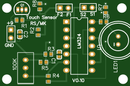
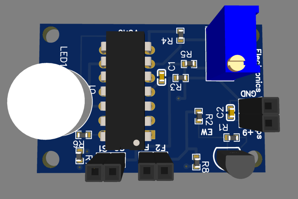
The LM324-based touch sensor circuit uses the four operational amplifiers inside the LM324 IC to detect the tiny electrical signal produced when a user touches the sensor pad. The circuit is powered from a +9 V supply connected through header H2, while the 2N3906 PNP transistor (Q1), together with R1, R2, C1, and C2, provides a filtered and stable reference voltage for the sensing stage. The touch electrodes are connected through headers H1 (Force lines) and H3 (Sense lines). The first two op-amps (U1.1 and U1.2) amplify the extremely small signal generated by the touch sensor and compare it against an adjustable threshold. Potentiometer RP1 (100 kΩ) allows the sensitivity of the touch sensor to be adjusted, while resistors R7 and R8 provide biasing and enable the circuit to operate with either a two-wire or four-wire touch sensor configuration. The outputs of these stages are then processed by U1.3 and U1.4, which act as comparators to produce a clean digital output that drives the red/green LED (LED1) through resistor R6, indicating when a touch has been detected.
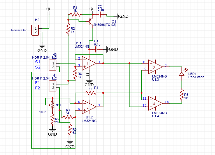
The notes included in the schematic explain the sensor connections and configuration options. "Potentiometer RP1 is used to adjust sensitivity." "Header H1 connects to the sensor's two 'force' lines." "Header H2 connects to the sensor's two optional 'Sense' lines." "R7 and R8 permit a two-line sensor configuration, but it then is sensitive to the series resistance of the force lines." For improved accuracy, the circuit supports a 4-wire configuration, where "connect F1 and S1 to magnetic contact #1, and F2 + S2 are connected to magnetic contact #2." Alternatively, for a simpler 2-wire sensor setup, "just connect F1 to one of the magnetic contacts and F2 to the other." This flexibility allows the circuit to be used with different sensor arrangements while maintaining reliable touch detection, making it suitable for DIY electronics projects, control panels, and educational demonstrations.
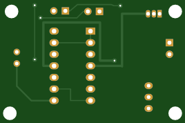
PCB Files
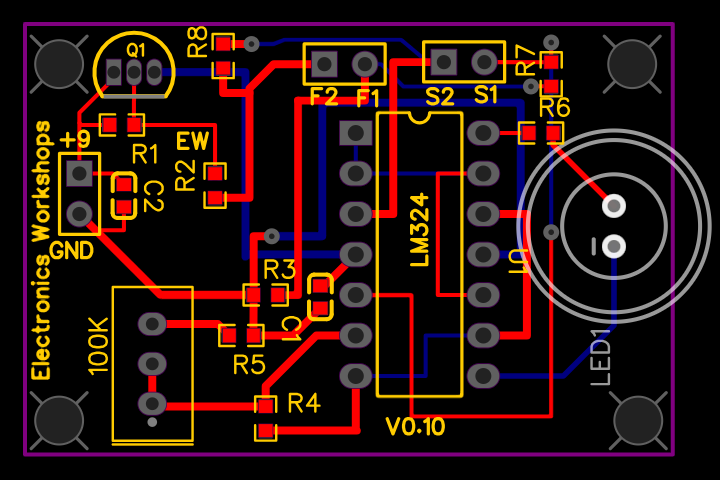
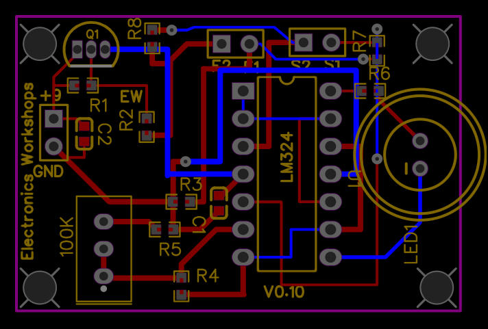
3D files
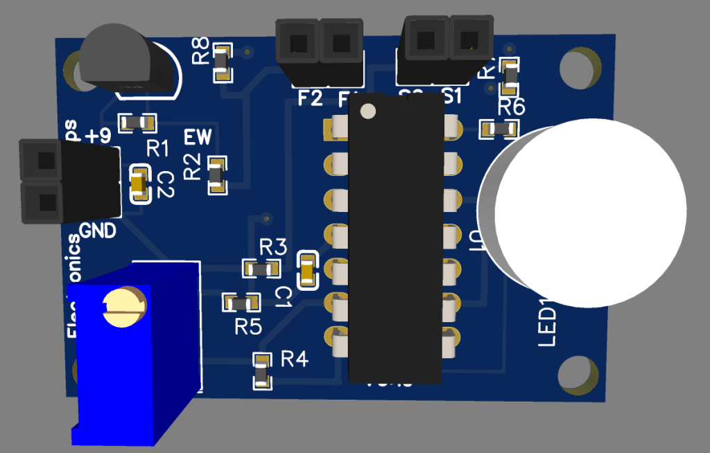
Conclusion
Designing a simple touch sensor using the LM324 is an excellent beginner electronics project that demonstrates how operational amplifiers can detect extremely small electrical signals generated by human touch. The circuit is inexpensive, reliable, and easy to assemble, making it suitable for students, hobbyists, and anyone interested in analog electronics.
For Full Project:
https://electronicsworkshops.com/design-simple-touch-sensor-using-lm324/
For Best Electronics Calculator:
Design Simple Touch Sensor Using LM324
Project images are for reference only. Actual production is based on the manufacturing files on the project page.
Please review the designer's notes (e.g., PCB thickness) and select the appropriate options.
PCBWay is not responsible
for issues caused by unsuitable parameter selections.
For more important ordering information, please refer to
Read More









Raspberry Pi 5 7 Inch Touch Screen IPS 1024x600 HD LCD HDMI-compatible Display for RPI 4B 3B+ OPI 5 AIDA64 PC Secondary Screen(Without Speaker)
BUY NOW

- Comments(0)
- Likes(0)
More by Rabin Poudel
-
 Automatic Water Pump Control System Using ESP-12F
IntroductionWater scarcity and wastage are major challenges in residential, agricultural, and indust...
Automatic Water Pump Control System Using ESP-12F
IntroductionWater scarcity and wastage are major challenges in residential, agricultural, and indust...
-
 Flood Detection and warning system using LORA and Arduino
IntroductionFloods are one of the most devastating natural disasters, causing immense damage to life...
Flood Detection and warning system using LORA and Arduino
IntroductionFloods are one of the most devastating natural disasters, causing immense damage to life...
-
 DIY LED Decoration Tiny Star PCB Project
IntroductionThe Tiny Star PCB is a small and fun DIY electronics project that is perfect for hobbyis...
DIY LED Decoration Tiny Star PCB Project
IntroductionThe Tiny Star PCB is a small and fun DIY electronics project that is perfect for hobbyis...
-
 Simple and Cheap Clap Switch Circuit
IntroductionThe Simple and Cheap Clap Switch Circuit is a practical and fun DIY electronics project ...
Simple and Cheap Clap Switch Circuit
IntroductionThe Simple and Cheap Clap Switch Circuit is a practical and fun DIY electronics project ...
-
 Arduino-based Mist Maker and Hand Dryer
IntroductionIn today’s world, automation and hygiene have become essential, especially in public pla...
Arduino-based Mist Maker and Hand Dryer
IntroductionIn today’s world, automation and hygiene have become essential, especially in public pla...
-
 MPL3115A2 Barometric Pressure, Altitude, and Temperature Sensor
IntroductionThe MPL3115A2 is a highly accurate, low-power digital barometric pressure sensor from NX...
MPL3115A2 Barometric Pressure, Altitude, and Temperature Sensor
IntroductionThe MPL3115A2 is a highly accurate, low-power digital barometric pressure sensor from NX...
-
 E-Speaker Using ESP32
IntroductionThe E-Speaker is a smart, portable, and versatile audio system built using the ESP32 mic...
E-Speaker Using ESP32
IntroductionThe E-Speaker is a smart, portable, and versatile audio system built using the ESP32 mic...
-
 Heart Rate Monitor Circuit Using Photoplethysmography (PPG)
IntroductionHeart rate is a vital physiological parameter that reflects the health and fitness of an...
Heart Rate Monitor Circuit Using Photoplethysmography (PPG)
IntroductionHeart rate is a vital physiological parameter that reflects the health and fitness of an...
-
 Automated Greenhouse Control System using ESP32
IntroductionAn automated greenhouse control system leverages technology to optimize plant growth con...
Automated Greenhouse Control System using ESP32
IntroductionAn automated greenhouse control system leverages technology to optimize plant growth con...
-
 STD CH330N USB to Serial Converter 5V
IntroductionThe CH330N is a versatile USB-to-serial converter chip that simplifies interfacing betwe...
STD CH330N USB to Serial Converter 5V
IntroductionThe CH330N is a versatile USB-to-serial converter chip that simplifies interfacing betwe...
-
 KY-032 Obstacle avoidance sensor module
IntroductionIntroduction to Obstacle Avoidance SensorsObstacle avoidance sensors are essential compo...
KY-032 Obstacle avoidance sensor module
IntroductionIntroduction to Obstacle Avoidance SensorsObstacle avoidance sensors are essential compo...
-
 BC547 BASED WATER LEVEL INDICATOR
IntroductionA water level indicator using a BC547 transistor is a simple and effective electronic pr...
BC547 BASED WATER LEVEL INDICATOR
IntroductionA water level indicator using a BC547 transistor is a simple and effective electronic pr...
-
 How to Design Own Arduino Wifi shield PCB
OverviewArduino wifi shield connects the Arduino with a wifi chip through the serial communication p...
How to Design Own Arduino Wifi shield PCB
OverviewArduino wifi shield connects the Arduino with a wifi chip through the serial communication p...
-
 DIY Air Quality Tester
OverviewIn this project “DIY Air Quality Tester” we use Node MCU microcontroller and air quality sen...
DIY Air Quality Tester
OverviewIn this project “DIY Air Quality Tester” we use Node MCU microcontroller and air quality sen...
-
 Digital Clock Using Arduino
OverviewIn this project, “Digital clock using Arduino” we will make a PCB board for digital clock an...
Digital Clock Using Arduino
OverviewIn this project, “Digital clock using Arduino” we will make a PCB board for digital clock an...
-
 Bluetooth Controlled car using Arduino
OverviewA Bluetooth Controlled Car Using Arduino is a fascinating DIY project that involves building...
Bluetooth Controlled car using Arduino
OverviewA Bluetooth Controlled Car Using Arduino is a fascinating DIY project that involves building...
-
 Design a Magnetic Sensor Using S411A
IntroductionMagnetic sensors are widely used in modern electronic systems for detecting the presence...
Design a Magnetic Sensor Using S411A
IntroductionMagnetic sensors are widely used in modern electronic systems for detecting the presence...
-
 Design Simple Touch Sensor Using LM324
IntroductionTouch sensors have become an essential part of modern electronic devices, replacing trad...
Design Simple Touch Sensor Using LM324
IntroductionTouch sensors have become an essential part of modern electronic devices, replacing trad...
-
SmallOLED - Live PC Stats, Animated Clocks & Audio Visualizer
637 0 3 -
"Talking Multimeter": Arduino-Based Speech Add-on for Multimeters with SCPI Protocol
366 0 1 -
Programmable Mist Maker - XIAO / QT PY Extension
2802 2 3 -
RadioHAT - Raspberry Pi radio development platform
2405 0 4 -
-
-
-
ARPS-2 – Arduino-Compatible Robot Project Shield for Arduino UNO
4496 0 6


















