


Design a Magnetic Sensor Using S411A
Introduction
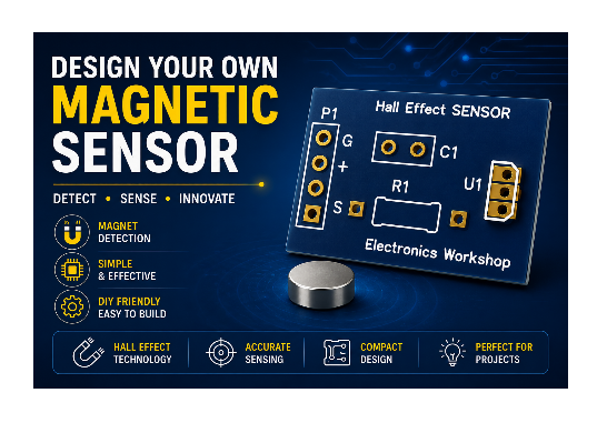
Magnetic sensors are widely used in modern electronic systems for detecting the presence of magnets without requiring physical contact. In this project, we will design a magnetic sensor using the S411A Hall Effect sensor, a compact and reliable device that converts changes in a magnetic field into a digital output signal. The circuit is simple, requires only a few components, and is an excellent project for beginners, students, and electronics enthusiasts who want to learn about magnetic field sensing and PCB design.
Whether you're building a proximity detector, door sensor, position detector, or automation project, the S411A Hall Effect sensor offers a reliable and low-cost solution.
For Full Project:
https://electronicsworkshops.com/design-a-magnetic-sensor-using-s411a/
For Best Electronics Calculator:
https://numericalcalculator.com/
What is a Hall Effect Sensor?
A Hall Effect sensor is a semiconductor device that detects magnetic fields by measuring the Hall voltage generated when a magnetic field passes through the sensor. Unlike mechanical switches, Hall Effect sensors have no moving parts, making them more durable, reliable, and suitable for high-speed switching applications.
- Hall Effect sensors are commonly used in:
- Door and window security systems
- Speed detection
- Position sensing
- Motor control
- Robotics
- Automotive electronics
- Industrial automation
- Consumer electronics
Why Choose the S411A Hall Effect Sensor?
The S411A is a digital Hall Effect sensor designed for accurate magnetic field detection. It provides a clean digital output when a magnetic field of sufficient strength is present, making it ideal for switching and sensing applications.
Advantages of the S411A
- Compact TO-92 package
- Digital output
- High sensitivity
- Low power consumption
- Fast response time
- Reliable operation
- Wide operating voltage range
- Easy to interface with LEDs and microcontrollers
Pin Out of S411A
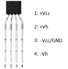
The S411A Hall Effect sensor is available in a compact 4-pin SIP (Single Inline Package), with each pin serving a specific function for magnetic field detection. Pin 1 (+VCC) is the positive power supply input, which powers the sensor using the recommended operating voltage. Pin 2 (+Vh) is the positive Hall voltage terminal, providing access to the internal Hall element for signal processing in certain applications. Pin 3 (−VCC/GND) serves as the ground or negative power supply connection, completing the power circuit. Pin 4 (−Vh) is the negative Hall voltage terminal, which works together with Pin 2 to generate the Hall voltage when a magnetic field is present. As a magnetic field passes through the sensor, a small Hall voltage is produced between the +Vh and −Vh terminals, and this signal can then be amplified or processed by external circuitry to detect the presence and strength of the magnetic field. This pin configuration makes the S411A well suited for magnetic sensing, position detection, speed measurement, and industrial automation applications.
Circuit diagram
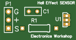
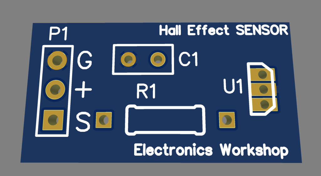
The circuit shown is a simple magnetic sensor module built around the SS411A Hall Effect sensor, designed to detect the presence of a magnetic field and provide a digital output. The module operates from a +5 V power supply, which is connected through the P1 header. The three pins of the header provide +5 V, Ground (GND), and the Output (OUT) signal, making it easy to interface the module with a microcontroller such as an Arduino, ESP32, or Raspberry Pi. The SS411A Hall Effect sensor (U1) continuously monitors the surrounding magnetic field. When a magnet of the correct polarity is brought close to the sensor, the internal Hall element detects the magnetic flux and changes the state of the output pin, producing a digital signal that can be used to trigger LEDs, relays, alarms, or other electronic circuits.
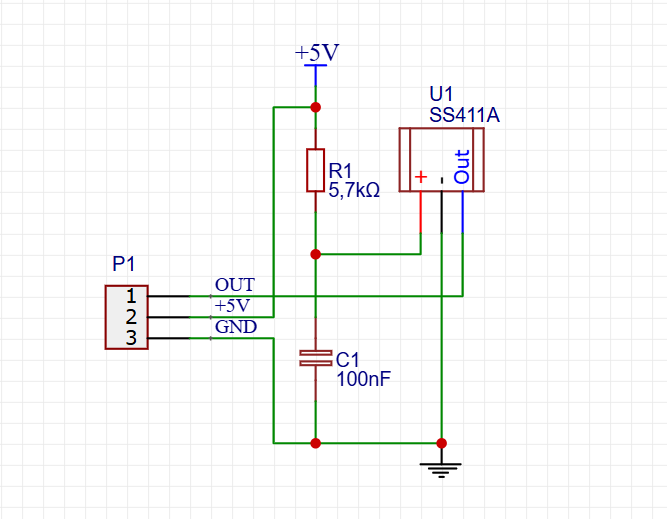
To ensure stable and reliable operation, the circuit includes a 5.7 kΩ pull-up resistor (R1) connected between the +5 V supply and the sensor's output. This resistor keeps the output in a logic HIGH state when no magnetic field is detected. When the sensor is activated by a magnet, it pulls the output LOW, creating a clear digital switching signal. A 100 nF ceramic capacitor (C1) is connected across the power supply rails to act as a decoupling capacitor, filtering electrical noise and minimizing voltage fluctuations that could otherwise cause false triggering. Together, the SS411A sensor, pull-up resistor, and decoupling capacitor form a simple, compact, and reliable magnetic sensing circuit suitable for applications such as door and window security systems, position sensing, speed detection, industrial automation, and DIY electronics projects.
PCB files
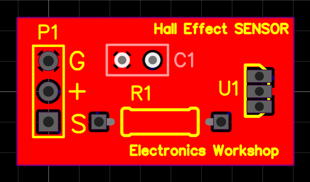
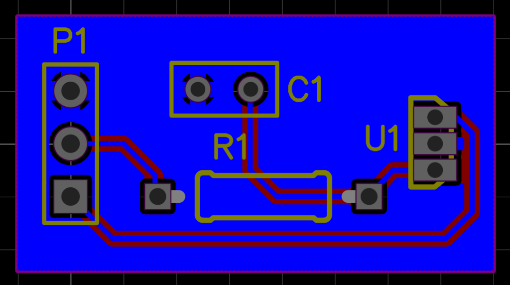
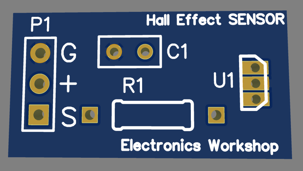
3d Files
Conclusion
Designing a magnetic sensor using the S411A Hall Effect sensor is an excellent way to explore contactless sensing technology. With only a few components, this project delivers reliable magnetic field detection suitable for a wide range of applications, from security systems and robotics to automation and industrial controls. Its simple design, low power consumption, and ease of integration make it an ideal project for beginners as well as experienced electronics enthusiasts looking for a dependable magnetic sensing solution.
Numerical Calculator
Best free online calculators for engineers, students and everyday life — from Ohm’s Law, LED resistors and RLC resonance to BMI, calories, pregnancy due dates and EV savings — each with live diagrams and step-by-step math.
For Full Project:
https://electronicsworkshops.com/design-a-magnetic-sensor-using-s411a/
Numerical calculator : https://numericalcalculator.com/
Design a Magnetic Sensor Using S411A
Project images are for reference only. Actual production is based on the manufacturing files on the project page.
Please review the designer's notes (e.g., PCB thickness) and select the appropriate options.
PCBWay is not responsible
for issues caused by unsuitable parameter selections.
For more important ordering information, please refer to
Read More









Raspberry Pi 5 7 Inch Touch Screen IPS 1024x600 HD LCD HDMI-compatible Display for RPI 4B 3B+ OPI 5 AIDA64 PC Secondary Screen(Without Speaker)
BUY NOW

- Comments(0)
- Likes(0)
More by Rabin Poudel
-
 Automatic Water Pump Control System Using ESP-12F
IntroductionWater scarcity and wastage are major challenges in residential, agricultural, and indust...
Automatic Water Pump Control System Using ESP-12F
IntroductionWater scarcity and wastage are major challenges in residential, agricultural, and indust...
-
 Flood Detection and warning system using LORA and Arduino
IntroductionFloods are one of the most devastating natural disasters, causing immense damage to life...
Flood Detection and warning system using LORA and Arduino
IntroductionFloods are one of the most devastating natural disasters, causing immense damage to life...
-
 DIY LED Decoration Tiny Star PCB Project
IntroductionThe Tiny Star PCB is a small and fun DIY electronics project that is perfect for hobbyis...
DIY LED Decoration Tiny Star PCB Project
IntroductionThe Tiny Star PCB is a small and fun DIY electronics project that is perfect for hobbyis...
-
 Simple and Cheap Clap Switch Circuit
IntroductionThe Simple and Cheap Clap Switch Circuit is a practical and fun DIY electronics project ...
Simple and Cheap Clap Switch Circuit
IntroductionThe Simple and Cheap Clap Switch Circuit is a practical and fun DIY electronics project ...
-
 Arduino-based Mist Maker and Hand Dryer
IntroductionIn today’s world, automation and hygiene have become essential, especially in public pla...
Arduino-based Mist Maker and Hand Dryer
IntroductionIn today’s world, automation and hygiene have become essential, especially in public pla...
-
 MPL3115A2 Barometric Pressure, Altitude, and Temperature Sensor
IntroductionThe MPL3115A2 is a highly accurate, low-power digital barometric pressure sensor from NX...
MPL3115A2 Barometric Pressure, Altitude, and Temperature Sensor
IntroductionThe MPL3115A2 is a highly accurate, low-power digital barometric pressure sensor from NX...
-
 E-Speaker Using ESP32
IntroductionThe E-Speaker is a smart, portable, and versatile audio system built using the ESP32 mic...
E-Speaker Using ESP32
IntroductionThe E-Speaker is a smart, portable, and versatile audio system built using the ESP32 mic...
-
 Heart Rate Monitor Circuit Using Photoplethysmography (PPG)
IntroductionHeart rate is a vital physiological parameter that reflects the health and fitness of an...
Heart Rate Monitor Circuit Using Photoplethysmography (PPG)
IntroductionHeart rate is a vital physiological parameter that reflects the health and fitness of an...
-
 Automated Greenhouse Control System using ESP32
IntroductionAn automated greenhouse control system leverages technology to optimize plant growth con...
Automated Greenhouse Control System using ESP32
IntroductionAn automated greenhouse control system leverages technology to optimize plant growth con...
-
 STD CH330N USB to Serial Converter 5V
IntroductionThe CH330N is a versatile USB-to-serial converter chip that simplifies interfacing betwe...
STD CH330N USB to Serial Converter 5V
IntroductionThe CH330N is a versatile USB-to-serial converter chip that simplifies interfacing betwe...
-
 KY-032 Obstacle avoidance sensor module
IntroductionIntroduction to Obstacle Avoidance SensorsObstacle avoidance sensors are essential compo...
KY-032 Obstacle avoidance sensor module
IntroductionIntroduction to Obstacle Avoidance SensorsObstacle avoidance sensors are essential compo...
-
 BC547 BASED WATER LEVEL INDICATOR
IntroductionA water level indicator using a BC547 transistor is a simple and effective electronic pr...
BC547 BASED WATER LEVEL INDICATOR
IntroductionA water level indicator using a BC547 transistor is a simple and effective electronic pr...
-
 How to Design Own Arduino Wifi shield PCB
OverviewArduino wifi shield connects the Arduino with a wifi chip through the serial communication p...
How to Design Own Arduino Wifi shield PCB
OverviewArduino wifi shield connects the Arduino with a wifi chip through the serial communication p...
-
 DIY Air Quality Tester
OverviewIn this project “DIY Air Quality Tester” we use Node MCU microcontroller and air quality sen...
DIY Air Quality Tester
OverviewIn this project “DIY Air Quality Tester” we use Node MCU microcontroller and air quality sen...
-
 Digital Clock Using Arduino
OverviewIn this project, “Digital clock using Arduino” we will make a PCB board for digital clock an...
Digital Clock Using Arduino
OverviewIn this project, “Digital clock using Arduino” we will make a PCB board for digital clock an...
-
 Bluetooth Controlled car using Arduino
OverviewA Bluetooth Controlled Car Using Arduino is a fascinating DIY project that involves building...
Bluetooth Controlled car using Arduino
OverviewA Bluetooth Controlled Car Using Arduino is a fascinating DIY project that involves building...
-
 Design a Magnetic Sensor Using S411A
IntroductionMagnetic sensors are widely used in modern electronic systems for detecting the presence...
Design a Magnetic Sensor Using S411A
IntroductionMagnetic sensors are widely used in modern electronic systems for detecting the presence...
-
 Design Simple Touch Sensor Using LM324
IntroductionTouch sensors have become an essential part of modern electronic devices, replacing trad...
Design Simple Touch Sensor Using LM324
IntroductionTouch sensors have become an essential part of modern electronic devices, replacing trad...
-
SmallOLED - Live PC Stats, Animated Clocks & Audio Visualizer
779 0 3 -
"Talking Multimeter": Arduino-Based Speech Add-on for Multimeters with SCPI Protocol
440 0 1 -
Programmable Mist Maker - XIAO / QT PY Extension
2902 2 3 -
RadioHAT - Raspberry Pi radio development platform
2474 0 4 -
-
-
-
ARPS-2 – Arduino-Compatible Robot Project Shield for Arduino UNO
4556 0 6


















