


How to Make Your Own NFC Reader Using PN512
Introduction
Near Field Communication (NFC) is a short‑range wireless communication technology operating at 13.56 MHz. It is widely used in contactless cards, access control, mobile payments, and smart devices. An NFC reader detects and communicates with NFC tags or cards placed very close to it.
This project explains how to design and build your own NFC reader using the PN512 NFC controller. The project covers the working principle, required components, hardware connections, software logic, and applications.
For Full Project:
https://electronicsworkshops.com/how-to-make-your-own-nfc-reader-using-pn512/
Objectives of the Project
To understand the working principle of NFC technology
To interface the PN512 NFC controller with a microcontroller
To design a simple and low‑cost NFC reader system
What is PN512?
The PN512 is an NFC reader IC developed by NXP Semiconductors. It supports contactless communication at 13.56 MHz and is compatible with several RFID/NFC standards such as:
SO/IEC 14443 Type A and Type B
MIFARE Classic and Ultralight
NFC Forum Type 2 tags
Key Features of PN512
Operating frequency: 13.56 MHz
Supports SPI, I²C, and UART interfaces
Low power consumption
Integrated CRC and framing
Supports read/write operations
Block Diagram
NFC Card → PN512 NFC Reader → Microcontroller → Serial Monitor / Display
The block diagram of the NFC reader system consists of an NFC card or tag, a PN512 NFC reader module, a microcontroller, and an output unit such as a serial monitor or display. The NFC card is brought close to the PN512 antenna, where communication takes place using a 13.56 MHz electromagnetic field. The PN512 acts as the core NFC controller, handling modulation, demodulation, and data framing. It communicates with the microcontroller through SPI, I²C, or UART interface. The microcontroller processes the received data and sends the output to a display or serial monitor for user interaction.
Working Principle
The working principle of the NFC reader using PN512 is based on electromagnetic induction. When powered on, the PN512 generates a 13.56 MHz RF field through its antenna. When an NFC card or tag enters this field, it gets energized wirelessly and transmits its stored information, such as the unique identification number (UID). The PN512 receives this signal, decodes the data, and forwards it to the microcontroller. The microcontroller then processes the data and displays it on the serial monitor or uses it for further applications like access control or authentication. This communication occurs over a very short distance, ensuring secure and fast data transfer.
Circuit Diagram
This schematic shows a complete PN512-based NFC reader circuit operating at 3.3 V. The power supply section uses multiple decoupling capacitors to provide a stable and noise-free voltage to the PN512’s digital, analog, and RF supply pins. A 27.12 MHz crystal oscillator with load capacitors generates the precise clock required for NFC operation. The PN512 NFC controller is the core of the circuit, responsible for generating the 13.56 MHz RF field, handling modulation and demodulation, and managing NFC communication protocols. The RF section, consisting of inductors, capacitors, and matching resistors, forms a tuned antenna matching network that efficiently transfers energy between the PN512 and the NFC antenna. Communication with an external microcontroller is achieved through the SPI interface pins (MOSI, MISO, SCK, and NSS), while control pins such as reset and address selection configure the device operation. When powered, the PN512 energizes an NFC tag through the antenna, receives the tag’s response, processes the data internally, and sends it to the microcontroller for further use.

Manufacturing Files
Gerber
gerberDownload
Bill Of Materials
NFC(PN512)Download
Position Files
NFC(PN512)-top-posDownload
PCB files


3D


Conclusion
This project demonstrates how to build an NFC reader using the PN512 controller. By interfacing the PN512 with a microcontroller, we can easily read NFC cards and tags. The system is reliable, cost‑effective, and suitable for various real‑world applications such as access control and authentication systems.
For Full Project:
https://electronicsworkshops.com/how-to-make-your-own-nfc-reader-using-pn512/
How to Make Your Own NFC Reader Using PN512
*PCBWay community is a sharing platform. We are not responsible for any design issues and parameter issues (board thickness, surface finish, etc.) you choose.


Raspberry Pi 5 7 Inch Touch Screen IPS 1024x600 HD LCD HDMI-compatible Display for RPI 4B 3B+ OPI 5 AIDA64 PC Secondary Screen(Without Speaker)
BUY NOW


- Comments(0)
- Likes(0)
More by Rabin Poudel
-
 Automatic Water Pump Control System Using ESP-12F
IntroductionWater scarcity and wastage are major challenges in residential, agricultural, and indust...
Automatic Water Pump Control System Using ESP-12F
IntroductionWater scarcity and wastage are major challenges in residential, agricultural, and indust...
-
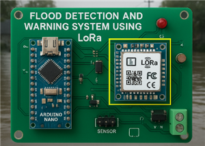 Flood Detection and warning system using LORA and Arduino
IntroductionFloods are one of the most devastating natural disasters, causing immense damage to life...
Flood Detection and warning system using LORA and Arduino
IntroductionFloods are one of the most devastating natural disasters, causing immense damage to life...
-
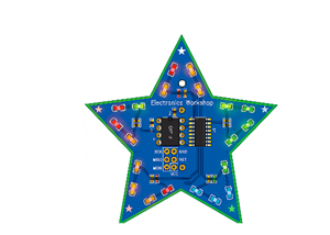 DIY LED Decoration Tiny Star PCB Project
IntroductionThe Tiny Star PCB is a small and fun DIY electronics project that is perfect for hobbyis...
DIY LED Decoration Tiny Star PCB Project
IntroductionThe Tiny Star PCB is a small and fun DIY electronics project that is perfect for hobbyis...
-
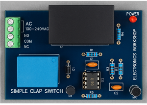 Simple and Cheap Clap Switch Circuit
IntroductionThe Simple and Cheap Clap Switch Circuit is a practical and fun DIY electronics project ...
Simple and Cheap Clap Switch Circuit
IntroductionThe Simple and Cheap Clap Switch Circuit is a practical and fun DIY electronics project ...
-
 Arduino-based Mist Maker and Hand Dryer
IntroductionIn today’s world, automation and hygiene have become essential, especially in public pla...
Arduino-based Mist Maker and Hand Dryer
IntroductionIn today’s world, automation and hygiene have become essential, especially in public pla...
-
 MPL3115A2 Barometric Pressure, Altitude, and Temperature Sensor
IntroductionThe MPL3115A2 is a highly accurate, low-power digital barometric pressure sensor from NX...
MPL3115A2 Barometric Pressure, Altitude, and Temperature Sensor
IntroductionThe MPL3115A2 is a highly accurate, low-power digital barometric pressure sensor from NX...
-
 E-Speaker Using ESP32
IntroductionThe E-Speaker is a smart, portable, and versatile audio system built using the ESP32 mic...
E-Speaker Using ESP32
IntroductionThe E-Speaker is a smart, portable, and versatile audio system built using the ESP32 mic...
-
 Heart Rate Monitor Circuit Using Photoplethysmography (PPG)
IntroductionHeart rate is a vital physiological parameter that reflects the health and fitness of an...
Heart Rate Monitor Circuit Using Photoplethysmography (PPG)
IntroductionHeart rate is a vital physiological parameter that reflects the health and fitness of an...
-
 Automated Greenhouse Control System using ESP32
IntroductionAn automated greenhouse control system leverages technology to optimize plant growth con...
Automated Greenhouse Control System using ESP32
IntroductionAn automated greenhouse control system leverages technology to optimize plant growth con...
-
 STD CH330N USB to Serial Converter 5V
IntroductionThe CH330N is a versatile USB-to-serial converter chip that simplifies interfacing betwe...
STD CH330N USB to Serial Converter 5V
IntroductionThe CH330N is a versatile USB-to-serial converter chip that simplifies interfacing betwe...
-
 KY-032 Obstacle avoidance sensor module
IntroductionIntroduction to Obstacle Avoidance SensorsObstacle avoidance sensors are essential compo...
KY-032 Obstacle avoidance sensor module
IntroductionIntroduction to Obstacle Avoidance SensorsObstacle avoidance sensors are essential compo...
-
 BC547 BASED WATER LEVEL INDICATOR
IntroductionA water level indicator using a BC547 transistor is a simple and effective electronic pr...
BC547 BASED WATER LEVEL INDICATOR
IntroductionA water level indicator using a BC547 transistor is a simple and effective electronic pr...
-
 How to Design Own Arduino Wifi shield PCB
OverviewArduino wifi shield connects the Arduino with a wifi chip through the serial communication p...
How to Design Own Arduino Wifi shield PCB
OverviewArduino wifi shield connects the Arduino with a wifi chip through the serial communication p...
-
 DIY Air Quality Tester
OverviewIn this project “DIY Air Quality Tester” we use Node MCU microcontroller and air quality sen...
DIY Air Quality Tester
OverviewIn this project “DIY Air Quality Tester” we use Node MCU microcontroller and air quality sen...
-
 Digital Clock Using Arduino
OverviewIn this project, “Digital clock using Arduino” we will make a PCB board for digital clock an...
Digital Clock Using Arduino
OverviewIn this project, “Digital clock using Arduino” we will make a PCB board for digital clock an...
-
 Bluetooth Controlled car using Arduino
OverviewA Bluetooth Controlled Car Using Arduino is a fascinating DIY project that involves building...
Bluetooth Controlled car using Arduino
OverviewA Bluetooth Controlled Car Using Arduino is a fascinating DIY project that involves building...
-
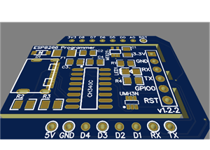 ESP8266 Programmer Board (USB-C Based)
IntroductionThe ESP8266 Programmer is a compact breakout board designed to simplify firmware uploadi...
ESP8266 Programmer Board (USB-C Based)
IntroductionThe ESP8266 Programmer is a compact breakout board designed to simplify firmware uploadi...
-
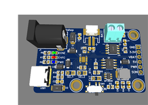 Power Management Board for Battery Powered Projects
IntroductionThe LiPo Power Board functions as a power controller for devices powered by batteries, m...
Power Management Board for Battery Powered Projects
IntroductionThe LiPo Power Board functions as a power controller for devices powered by batteries, m...
-
-
ARPS-2 – Arduino-Compatible Robot Project Shield for Arduino UNO
2511 0 5 -
A Compact Charging Breakout Board For Waveshare ESP32-C3
2963 3 8 -
AI-driven LoRa & LLM-enabled Kiosk & Food Delivery System
3174 2 1 -
-
-
-
ESP32-C3 BLE Keyboard - Battery Powered with USB-C Charging
3233 0 2


