


|
|
High Voltage trafo from old CRT Monitor |
x 1 | |
|
|
PC Power supply |
x 1 |

|
Soldering iron |
|

|
Soldering Iron Wire Welding Lead Roll |
The simplest way to make a quality HV (High Voltage) source from a PC power supply
This time I will present you how to make a quality High Voltage source in a very simple way. For this purpose I will use a old PC power supply, but it can also be used new one, whose price is very low, in the range of ten dollars due to mass production nowadays. During the testing I will use several different power supplies with different defined power and brands.
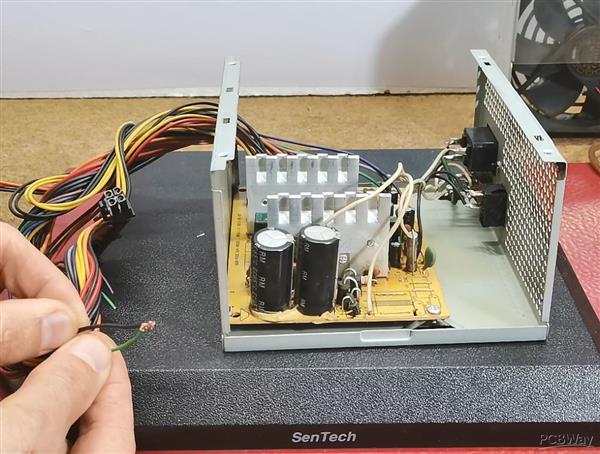
And the best information is that when making these device we will not make complex modifications in the power supply itself, which means that the device will be able to be made by those less experienced in this field. In that way, we will use almost all protection and safety procedures that are taken during the design of these power supplies. These devices are usually full of dust due to the way they work, so I first cleaned it well.

If you want to make a PCB for your project, PCBway is a great choice for you. PCBway is one of the most experienced PCB manufacturing company in China in field of PCB prototype and fabrication. They have a large online community where you can find a Open Source projects, and you can also share your project there. From my personal experience I can tell you that on this community you can find many useful projects
The picture below shows a standard PC power supply circuit, so basically all power supplies are based on the same principle of operation.

Now lets see the basic parts of one PC power supply:
- Input part, symetric rectifier with four diodes and filter capacitors
- Fuse and NTC resistor
- Oscillator integrated circuit(usually TL494)
- Two power switching Transistors or Mosfets
- Switching Transformers (Main transformer is bigger one)
- Shotky diodes , Choke , and output filter capacitors.
If the power supply has its own switch, it is necessary to short-circuit the Green wire with ground (any black wire). In my case, the power supply is activated with its own switch.
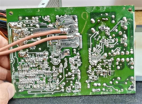
And now, the only modification we need to make is to remove the Schottky diodes, which is easiest to do together with the aluminum heatsink. For this operation we usually need a soldering iron with a higher power or a higher temperature at the tip.

After unsoldering the diodes, first we need to carefully examine the PCB with a magnifying glass, and if we made a short circuit during desoldering, repair it. It is good to mention that with this type of modification 4 of the 5 power supplies I owned worked, and one did not start and I needed to bypass the protection circuit, but more on that procedure in one of the next videos.
Next, we will use the secondary of the Main Transformer to drive the High Voltage Transformer.
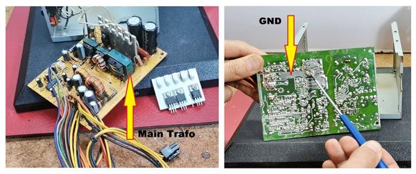
As can be seen in this case, always one terminal of the transformer is connected to the ground. In all cases, the ground lead will be our one electrode. The other electrode is usually one of the leads next to this one, regardless of whether it is on the left or right side. In these two places we need to solder an insulated wire with a cross section of at least 1.5mm. I use copper wire with a diameter of 2.5 mm insulated with a heat-resistant silicon insulator.
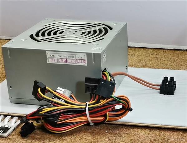
Now we need to somehow conduct these two wires to the outside and connect them to a terminal. Of course, while performing all these operations, the power supply must be disconnected from the mains. Let me also mention that these wires in this case have no function and I can remove all of them, except for the green and one black wire, for the reasons I mentioned before.
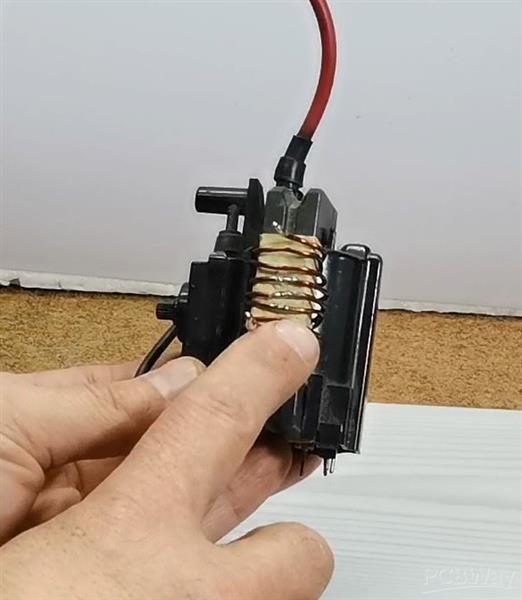
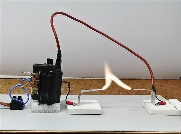
And now, a few words about the high-voltage transformer. In my case, it is a transformer-cascade taken from an old CRT monitor, on whose core is wound 7-10 turns of varnished copper wire with a diameter of 1mm or more. On several parts of the coil there are places for taping, so that we can make more precise adjustments depending on the type of power supply. If the number of primary windings of the trafo is well chosen, the device can work for a long time without any heating of the switching transistors. In order not to overload, the number of primary windings should be selected so that the spark does not exceed a length of 5-7 cm.
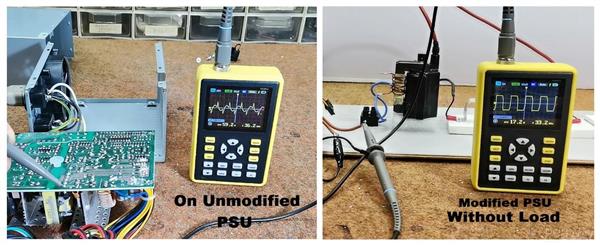
It would be good to look at the shape of the signal at the output of the mains transformer with, and without load. As you can see the shape without load is rectangular with a frequency of 32KHz and a peak to peak voltage of 24V
And finally, a short conclusion: Usually, for HV experiments is used so-called ZVS driver, but damage to the mosfets often occurs due to its low efficiency. I made this device as a basis for future projects related to High Voltage, because it is compact, easy to make, galvanically isolated from the mains and also stable during long-term operation. Although it looks simple, this project should be done very carefully. During testing I damaged two power supplies, one due to overload and the other due to carelessness. After any modification, we should always first assemble the power supply and then test if it works for security reasons. In each test, we first start with the largest number of turns of the primary of the HV transformer, and then gradually reduce.
SAFETY NOTE: Please do not attempt to recreate the experiments shown on this video unless you are familiar with High Voltage Safety Techniques! Direct Current even above 60V maybe lethal, even when the AC supply voltage has been disconnected due to the stored energy in the capacitors.
The simplest way to make a quality HV (High Voltage) source from a PC power supply


Raspberry Pi 5 7 Inch Touch Screen IPS 1024x600 HD LCD HDMI-compatible Display for RPI 4B 3B+ OPI 5 AIDA64 PC Secondary Screen(Without Speaker)
BUY NOW


- Comments(0)
- Likes(1)
More by Mirko Pavleski
-
 Arduino 3D Printed self Balancing Cube
Self-balancing devices are electronic devices that use sensors and motors to keep themselves balanc...
Arduino 3D Printed self Balancing Cube
Self-balancing devices are electronic devices that use sensors and motors to keep themselves balanc...
-
 Retro Analog VU Meter on Round dispalys (ESP32 and GC9A01)
Recently, in one of my previous videos I presented you a Retro VU Meter project on round displays ...
Retro Analog VU Meter on Round dispalys (ESP32 and GC9A01)
Recently, in one of my previous videos I presented you a Retro VU Meter project on round displays ...
-
 Ultimate 2-Player Reaction Timer with WS2812B LED Strips & Arduino
Arcade reaction game is a genre of play designed to test a player's physical response time and hand...
Ultimate 2-Player Reaction Timer with WS2812B LED Strips & Arduino
Arcade reaction game is a genre of play designed to test a player's physical response time and hand...
-
 Building a Vintage Tube-Style Internet Radio with Raspberry Pi & Rotary Encoder
Internet radio (also known as web radio or net radio) is a digital audio service transmitted via th...
Building a Vintage Tube-Style Internet Radio with Raspberry Pi & Rotary Encoder
Internet radio (also known as web radio or net radio) is a digital audio service transmitted via th...
-
 DIY Smart Code Lock with CrowPanel 1.28 ESP32 Rotary Display
A code lock is a keyless security device—either mechanical or electronic—that restricts access to d...
DIY Smart Code Lock with CrowPanel 1.28 ESP32 Rotary Display
A code lock is a keyless security device—either mechanical or electronic—that restricts access to d...
-
 SDR Panadapter for Vintage Tube Radios – Step-by-Step Tutorial
A radio panadapter (or panoramic adapter) is a device or software tool used in amateur radio and ot...
SDR Panadapter for Vintage Tube Radios – Step-by-Step Tutorial
A radio panadapter (or panoramic adapter) is a device or software tool used in amateur radio and ot...
-
 Oscilloscope Clock Simulation on a Round ESP32 Display
An oscilloscope clock is a circuit that turns an old analog oscilloscope into a stylish, retro-them...
Oscilloscope Clock Simulation on a Round ESP32 Display
An oscilloscope clock is a circuit that turns an old analog oscilloscope into a stylish, retro-them...
-
 DIY Simple GU32 Tube Stereo Amplifier (2x3W on 12VDC)
Vacuum tube amplifiers are often favored for their smooth harmonic distortion, especially in the low...
DIY Simple GU32 Tube Stereo Amplifier (2x3W on 12VDC)
Vacuum tube amplifiers are often favored for their smooth harmonic distortion, especially in the low...
-
 DIY 3-Display OLED Clock with Arduino and I2C Multiplexer
In this video I want to present you another unusual clock to add to my large collection of such DIY...
DIY 3-Display OLED Clock with Arduino and I2C Multiplexer
In this video I want to present you another unusual clock to add to my large collection of such DIY...
-
 Build a 5-Day forecast Raspberry Pi Weather Dashboard (Step-by-Step)
Recently in one of my previous videos,I introduced you to the 7 inch Elecrow Pi Terminal and how to...
Build a 5-Day forecast Raspberry Pi Weather Dashboard (Step-by-Step)
Recently in one of my previous videos,I introduced you to the 7 inch Elecrow Pi Terminal and how to...
-
 ESP32 Aneroid Barometer using Squareline Studio and LVGL on CrowPanel Round display
A barometer is a scientific instrument used to measure atmospheric pressure. Rising Pressure genera...
ESP32 Aneroid Barometer using Squareline Studio and LVGL on CrowPanel Round display
A barometer is a scientific instrument used to measure atmospheric pressure. Rising Pressure genera...
-
 LINAMP Project – Winamp-Style Audio Front Panel on Raspberry Pi 5
Winamp is one of the most iconic and historically significant digital media players ever created. I...
LINAMP Project – Winamp-Style Audio Front Panel on Raspberry Pi 5
Winamp is one of the most iconic and historically significant digital media players ever created. I...
-
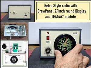 Retro Style radio with CrowPanel 2.1inch round Display (TEA5767)
Some time ago I presented you a clock project with CrowPanel 2.1inch-HMI ESP32 Rotary Display 480*4...
Retro Style radio with CrowPanel 2.1inch round Display (TEA5767)
Some time ago I presented you a clock project with CrowPanel 2.1inch-HMI ESP32 Rotary Display 480*4...
-
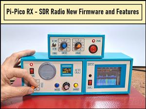 Pi-Pico RX - SDR Radio with New Firmware and Features
A few months ago I presented you a wonderful SDR radio project by DawsonJon 101 Things. In short, i...
Pi-Pico RX - SDR Radio with New Firmware and Features
A few months ago I presented you a wonderful SDR radio project by DawsonJon 101 Things. In short, i...
-
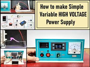 How to make simple Variable HIGH VOLTAGE Power Supply
High Voltage Power Supply is usually understood as a device that is capable of generating a voltage...
How to make simple Variable HIGH VOLTAGE Power Supply
High Voltage Power Supply is usually understood as a device that is capable of generating a voltage...
-
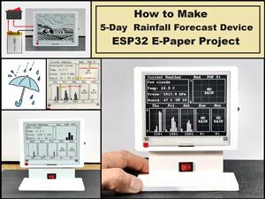 DIY 5-Day Rainfall Forecast Device - ESP32 E-Paper Project
In several of my previous projects I have presented ways to make weather stations, but this time I ...
DIY 5-Day Rainfall Forecast Device - ESP32 E-Paper Project
In several of my previous projects I have presented ways to make weather stations, but this time I ...
-
 Build simple Retro Style VFO (Variable frequency oscillator) with Crowoanel 1.28 inch Round Display
Today I received a shipment with a Small round LCD display from Elecrow. The device is packed in tw...
Build simple Retro Style VFO (Variable frequency oscillator) with Crowoanel 1.28 inch Round Display
Today I received a shipment with a Small round LCD display from Elecrow. The device is packed in tw...
-
 Human vs Robot – Rock Paper Scissors with MyCobot 280 M5Stack
Today I received a package containing the few Elephant Robotics products. The shipment is well pack...
Human vs Robot – Rock Paper Scissors with MyCobot 280 M5Stack
Today I received a package containing the few Elephant Robotics products. The shipment is well pack...
-
-
ARPS-2 – Arduino-Compatible Robot Project Shield for Arduino UNO
1308 0 4 -
A Compact Charging Breakout Board For Waveshare ESP32-C3
1830 3 7 -
AI-driven LoRa & LLM-enabled Kiosk & Food Delivery System
1822 2 0 -
-
-
-
ESP32-C3 BLE Keyboard - Battery Powered with USB-C Charging
1992 0 1 -


