


Inverter Circuit Using LaunchXL F28379D
Introduction
In this project, we design and implement a DSP-controlled inverter circuit using the LaunchXL F28379D development board. This project demonstrates how a high-performance digital controller can be used to generate precise PWM signals, control switching devices, and achieve efficient DC-to-AC conversion.
For Full Project:
https://electronicsworkshops.com/inverter-circuit-using-launchxl-f28379d/

This project is ideal for:
Power electronics learners
EV and motor control engineers
Students working on DSP-based inverter projects
Researchers exploring real-time control using TI C2000 controllers
What Is an Inverter?
An inverter is an electronic circuit that converts direct current (DC) into alternating current (AC) at a desired voltage and frequency.
Common Applications of Inverters
An inverter is an electronic circuit that converts direct current (DC) into alternating current (AC) at a desired voltage and frequency.
Common Applications of Inverters
Electric vehicle traction inverters
Solar power systems
UPS and backup power systems
Variable frequency drives (VFDs)
Industrial motor control
Why Use LaunchXL F28379D for Inverter Design?

The LaunchXL F28379D is based on Texas Instruments’ C2000 Delfino™ DSP, which is specifically designed for real-time control applications such as inverters, converters, and motor drives.
Key Advantages
Dual-core CPU (CPU1 + CPU2)
High-resolution PWM (HRPWM)
Fast ADCs for voltage and current sensing
Real-time control capability
Excellent support for motor control and power electronics
Because of these features, the F28379D is widely used in EV inverters, onboard chargers, and industrial drives.
Gate Driver and Signal Conditioning Circuit Explanation
This circuit represents the gate driver and PWM signal conditioning stage of the inverter. Its main role is to safely convert low-voltage PWM signals from the LaunchXL F28379D into high-current, high-voltage gate drive signals required to control the inverter power switches (IGBTs or MOSFETs).

This circuit is the gate driver stage of the inverter, used to interface the LaunchXL F28379D DSP with the inverter power switches (MOSFETs or IGBTs).
The PWM signals (PWM_1 to PWM_4) generated by the F28379D are first passed through transistor-based signal conditioning. This stage improves noise immunity, provides buffering, and protects the DSP from the high-power section.
The conditioned PWM signals are then fed into the IR2110 gate driver ICs. Each IR2110 drives one inverter leg by providing:
High-side gate drive (HO)
Low-side gate drive (LO)
A bootstrap circuit (diode and capacitor) is used to generate the floating supply required for high-side switching. This allows the high-side MOSFET/IGBT to turn ON even when its source/emitter is at high voltage.
The circuit operates with +5 V logic supply and +12 V gate drive supply, with proper decoupling capacitors to ensure stable and reliable operation.
Finally, all gate outputs and feedback signals are routed through a connector to the inverter power stage, making the design modular and easy to integrate.
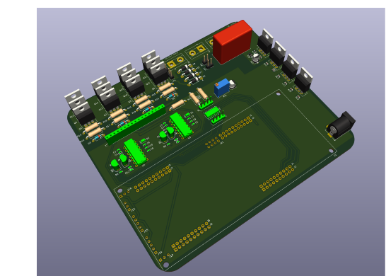
Inverter Power Stage and Output Section
This circuit represents the power conversion stage of the inverter, where the DC input is converted into AC power and delivered to the load through a transformer.

The inverter is built using IRF3205 MOSFETs arranged in a full-bridge configuration. These MOSFETs are driven by the gate driver circuit (IR2110), receiving high-side and low-side control signals (1HO, 1LO, 2HO, 2LO) generated by the LaunchXL F28379D.
When the MOSFETs switch alternately according to the SPWM signals, the DC input is converted into a high-frequency AC waveform at the transformer primary. The fast switching diodes (1N4148) protect the gates from voltage spikes, while gate resistors control switching speed and reduce ringing.
The transformer provides:
Voltage level conversion
Electrical isolation
Output power transfer
On the secondary side, an RC snubber/filter network smooths the waveform and reduces noise. The output feedback voltage (VFB) is scaled using resistors and capacitors and sent back to the DSP for closed-loop voltage control.
Jumpers are provided for testing, configuration, and debugging, allowing flexible operation during development.
PCB Files

3D Files

Conclusion
This project demonstrates a complete DSP-controlled inverter circuit using LaunchXL F28379D. By combining powerful hardware with real-time control algorithms, the system delivers high-quality AC output suitable for modern power electronics applications.
The LaunchXL F28379D proves to be an excellent choice for inverter design due to its high-speed processing, advanced PWM features, and strong protection mechanisms.
For Full Project:
https://electronicsworkshops.com/inverter-circuit-using-launchxl-f28379d/
Inverter Circuit Using LaunchXL F28379D
*PCBWay community is a sharing platform. We are not responsible for any design issues and parameter issues (board thickness, surface finish, etc.) you choose.


Raspberry Pi 5 7 Inch Touch Screen IPS 1024x600 HD LCD HDMI-compatible Display for RPI 4B 3B+ OPI 5 AIDA64 PC Secondary Screen(Without Speaker)
BUY NOW

- Comments(0)
- Likes(0)
More by Rabin Poudel
-
 Automatic Water Pump Control System Using ESP-12F
IntroductionWater scarcity and wastage are major challenges in residential, agricultural, and indust...
Automatic Water Pump Control System Using ESP-12F
IntroductionWater scarcity and wastage are major challenges in residential, agricultural, and indust...
-
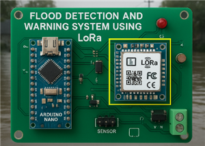 Flood Detection and warning system using LORA and Arduino
IntroductionFloods are one of the most devastating natural disasters, causing immense damage to life...
Flood Detection and warning system using LORA and Arduino
IntroductionFloods are one of the most devastating natural disasters, causing immense damage to life...
-
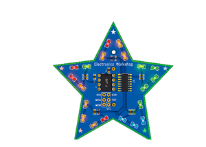 DIY LED Decoration Tiny Star PCB Project
IntroductionThe Tiny Star PCB is a small and fun DIY electronics project that is perfect for hobbyis...
DIY LED Decoration Tiny Star PCB Project
IntroductionThe Tiny Star PCB is a small and fun DIY electronics project that is perfect for hobbyis...
-
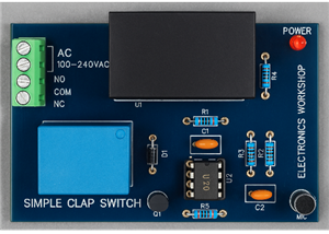 Simple and Cheap Clap Switch Circuit
IntroductionThe Simple and Cheap Clap Switch Circuit is a practical and fun DIY electronics project ...
Simple and Cheap Clap Switch Circuit
IntroductionThe Simple and Cheap Clap Switch Circuit is a practical and fun DIY electronics project ...
-
 Arduino-based Mist Maker and Hand Dryer
IntroductionIn today’s world, automation and hygiene have become essential, especially in public pla...
Arduino-based Mist Maker and Hand Dryer
IntroductionIn today’s world, automation and hygiene have become essential, especially in public pla...
-
 MPL3115A2 Barometric Pressure, Altitude, and Temperature Sensor
IntroductionThe MPL3115A2 is a highly accurate, low-power digital barometric pressure sensor from NX...
MPL3115A2 Barometric Pressure, Altitude, and Temperature Sensor
IntroductionThe MPL3115A2 is a highly accurate, low-power digital barometric pressure sensor from NX...
-
 E-Speaker Using ESP32
IntroductionThe E-Speaker is a smart, portable, and versatile audio system built using the ESP32 mic...
E-Speaker Using ESP32
IntroductionThe E-Speaker is a smart, portable, and versatile audio system built using the ESP32 mic...
-
 Heart Rate Monitor Circuit Using Photoplethysmography (PPG)
IntroductionHeart rate is a vital physiological parameter that reflects the health and fitness of an...
Heart Rate Monitor Circuit Using Photoplethysmography (PPG)
IntroductionHeart rate is a vital physiological parameter that reflects the health and fitness of an...
-
 Automated Greenhouse Control System using ESP32
IntroductionAn automated greenhouse control system leverages technology to optimize plant growth con...
Automated Greenhouse Control System using ESP32
IntroductionAn automated greenhouse control system leverages technology to optimize plant growth con...
-
 STD CH330N USB to Serial Converter 5V
IntroductionThe CH330N is a versatile USB-to-serial converter chip that simplifies interfacing betwe...
STD CH330N USB to Serial Converter 5V
IntroductionThe CH330N is a versatile USB-to-serial converter chip that simplifies interfacing betwe...
-
 KY-032 Obstacle avoidance sensor module
IntroductionIntroduction to Obstacle Avoidance SensorsObstacle avoidance sensors are essential compo...
KY-032 Obstacle avoidance sensor module
IntroductionIntroduction to Obstacle Avoidance SensorsObstacle avoidance sensors are essential compo...
-
 BC547 BASED WATER LEVEL INDICATOR
IntroductionA water level indicator using a BC547 transistor is a simple and effective electronic pr...
BC547 BASED WATER LEVEL INDICATOR
IntroductionA water level indicator using a BC547 transistor is a simple and effective electronic pr...
-
 How to Design Own Arduino Wifi shield PCB
OverviewArduino wifi shield connects the Arduino with a wifi chip through the serial communication p...
How to Design Own Arduino Wifi shield PCB
OverviewArduino wifi shield connects the Arduino with a wifi chip through the serial communication p...
-
 DIY Air Quality Tester
OverviewIn this project “DIY Air Quality Tester” we use Node MCU microcontroller and air quality sen...
DIY Air Quality Tester
OverviewIn this project “DIY Air Quality Tester” we use Node MCU microcontroller and air quality sen...
-
 Digital Clock Using Arduino
OverviewIn this project, “Digital clock using Arduino” we will make a PCB board for digital clock an...
Digital Clock Using Arduino
OverviewIn this project, “Digital clock using Arduino” we will make a PCB board for digital clock an...
-
 Bluetooth Controlled car using Arduino
OverviewA Bluetooth Controlled Car Using Arduino is a fascinating DIY project that involves building...
Bluetooth Controlled car using Arduino
OverviewA Bluetooth Controlled Car Using Arduino is a fascinating DIY project that involves building...
-
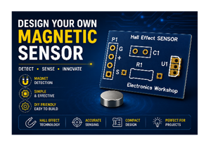 Design a Magnetic Sensor Using S411A
IntroductionMagnetic sensors are widely used in modern electronic systems for detecting the presence...
Design a Magnetic Sensor Using S411A
IntroductionMagnetic sensors are widely used in modern electronic systems for detecting the presence...
-
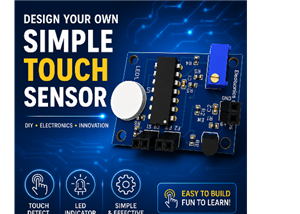 Design Simple Touch Sensor Using LM324
IntroductionTouch sensors have become an essential part of modern electronic devices, replacing trad...
Design Simple Touch Sensor Using LM324
IntroductionTouch sensors have become an essential part of modern electronic devices, replacing trad...
-
Programmable Mist Maker - XIAO / QT PY Extension
839 1 0 -
RadioHAT - Raspberry Pi radio development platform
674 0 2 -
-
-
-
-
ARPS-2 – Arduino-Compatible Robot Project Shield for Arduino UNO
3133 0 6 -
A Compact Charging Breakout Board For Waveshare ESP32-C3
3763 3 8 -
AI-driven LoRa & LLM-enabled Kiosk & Food Delivery System
4092 2 2


