


How to make custom Ultrasonic sensor?
Project Overview
This project involves designing custom hardware for an ultrasonic distance measurement system from scratch. The system will measure distances from 2cm to 400cm with ±1cm accuracy using ultrasonic pulse-echo time-of-flight measurement.
FOR FULL PROJECT:
https://electronicsworkshops.com/flood-detection-and-warning-system-using-lora-and-arduino/
Introduction
Distance measurement is a key requirement in many electronic and automotive applications such as parking assistance systems, obstacle detection, robotics, industrial automation, and smart devices. Ultrasonic sensors are widely used for this purpose because they are low cost, reliable, and work in various lighting conditions.
Most projects use ready-made ultrasonic modules. However, this project focuses on designing our own ultrasonic sensor hardware from scratch, including signal generation, signal reception, processing, and distance calculation. This approach helps in understanding the core electronics, timing principles, and hardware design challenges involved in ultrasonic sensing.
Working Principle of Ultrasonic Distance Measurement
Ultrasonic sensors work on the echo principle, similar to how bats navigate.

Basic Concept:
The transmitter sends a high-frequency ultrasonic pulse (typically 40 kHz).
The sound wave travels through air and hits an object.
The wave reflects back and is received by the receiver.
The time taken for the pulse to return is measured.
Distance is calculated using the speed of sound.
Distance Formula:
Distance=Time×Speed of Sound2\text{Distance} = \frac{\text{Time} \times \text{Speed of Sound}}{2}Distance=2Time×Speed of Sound
Speed of sound ≈ 343 m/s at 25°C
Division by 2 is required because the pulse travels to the object and back
Working Principle
Signal Flow:
Oscillator (U74 + G93-3) → generates 40kHz signal
Driver ICs (U78, U79) → amplify current capability
Transformer (T1074) → steps voltage up to 100-200Vpp
Matching network (L1, capacitors) → tunes to transducer resonance
Ultrasonic Transmitter → emits 40kHz sound waves
The receiving transducer converts reflected sound waves into a weak electrical signal.
The signal is amplified using a high-gain amplifier.
Noise and unwanted frequencies are removed using a band-pass filter.
Circuit Diagram
This custom ultrasonic sensor circuit takes the very weak echo signal from the ultrasonic receiver, AC-couples it and amplifies it in two stages using an MCP602 dual op-amp biased at mid-supply so it can work from a single power source; the amplified ultrasonic signal is then DC-blocked and rectified using diodes to convert it into a detectable pulse, which drives an NPN transistor acting as a switch to produce a clean logic-level output, making the circuit suitable for reliably detecting ultrasonic echoes and interfacing directly with a microcontroller or timing circuit for distance measurement.

This circuit is the ultrasonic transmitter and communication interface section: the ultrasonic transducer A1 generates ultrasonic pulses driven from the control signals, while power enters through connector J1 and is filtered by a ferrite bead (FB1), protection diode (D3), and decoupling capacitors to provide clean VCC; the MAX232 (U2) converts logic-level TX/RX signals (T1IN, T2IN, R1IN, R2IN) to proper RS-232 voltage levels using its charge-pump capacitors (C7–C11), enabling reliable communication between a microcontroller and external systems (PC or tester), while the surrounding capacitors ensure stable voltage generation and noise-free operation for accurate ultrasonic transmission and data exchange.

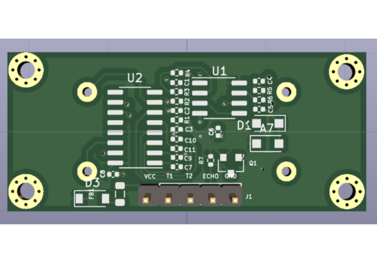
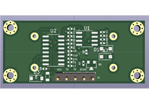
PCB

3D


Advantages of Custom Hardware Design
Better understanding of ultrasonic technology
Flexible design for specific applications
Cost optimization in mass production
Improved reliability and tuning
FOR FULL PROJECT:
https://electronicsworkshops.com/flood-detection-and-warning-system-using-lora-and-arduino/
Conclusion
This project successfully explains the design and development of custom ultrasonic distance measurement hardware. By designing the transmitter, receiver, and signal processing circuits independently, we gain deep insight into ultrasonic sensing technology. The system accurately measures distance using the time-of-flight method and can be further enhanced for automotive and industrial applications.
How to make custom Ultrasonic sensor?
*PCBWay community is a sharing platform. We are not responsible for any design issues and parameter issues (board thickness, surface finish, etc.) you choose.


Raspberry Pi 5 7 Inch Touch Screen IPS 1024x600 HD LCD HDMI-compatible Display for RPI 4B 3B+ OPI 5 AIDA64 PC Secondary Screen(Without Speaker)
BUY NOW

- Comments(0)
- Likes(0)
More by Rabin Poudel
-
 Automatic Water Pump Control System Using ESP-12F
IntroductionWater scarcity and wastage are major challenges in residential, agricultural, and indust...
Automatic Water Pump Control System Using ESP-12F
IntroductionWater scarcity and wastage are major challenges in residential, agricultural, and indust...
-
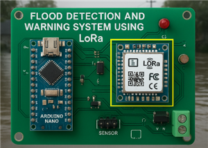 Flood Detection and warning system using LORA and Arduino
IntroductionFloods are one of the most devastating natural disasters, causing immense damage to life...
Flood Detection and warning system using LORA and Arduino
IntroductionFloods are one of the most devastating natural disasters, causing immense damage to life...
-
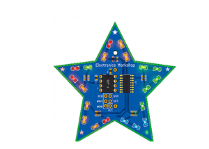 DIY LED Decoration Tiny Star PCB Project
IntroductionThe Tiny Star PCB is a small and fun DIY electronics project that is perfect for hobbyis...
DIY LED Decoration Tiny Star PCB Project
IntroductionThe Tiny Star PCB is a small and fun DIY electronics project that is perfect for hobbyis...
-
 Simple and Cheap Clap Switch Circuit
IntroductionThe Simple and Cheap Clap Switch Circuit is a practical and fun DIY electronics project ...
Simple and Cheap Clap Switch Circuit
IntroductionThe Simple and Cheap Clap Switch Circuit is a practical and fun DIY electronics project ...
-
 Arduino-based Mist Maker and Hand Dryer
IntroductionIn today’s world, automation and hygiene have become essential, especially in public pla...
Arduino-based Mist Maker and Hand Dryer
IntroductionIn today’s world, automation and hygiene have become essential, especially in public pla...
-
 MPL3115A2 Barometric Pressure, Altitude, and Temperature Sensor
IntroductionThe MPL3115A2 is a highly accurate, low-power digital barometric pressure sensor from NX...
MPL3115A2 Barometric Pressure, Altitude, and Temperature Sensor
IntroductionThe MPL3115A2 is a highly accurate, low-power digital barometric pressure sensor from NX...
-
 E-Speaker Using ESP32
IntroductionThe E-Speaker is a smart, portable, and versatile audio system built using the ESP32 mic...
E-Speaker Using ESP32
IntroductionThe E-Speaker is a smart, portable, and versatile audio system built using the ESP32 mic...
-
 Heart Rate Monitor Circuit Using Photoplethysmography (PPG)
IntroductionHeart rate is a vital physiological parameter that reflects the health and fitness of an...
Heart Rate Monitor Circuit Using Photoplethysmography (PPG)
IntroductionHeart rate is a vital physiological parameter that reflects the health and fitness of an...
-
 Automated Greenhouse Control System using ESP32
IntroductionAn automated greenhouse control system leverages technology to optimize plant growth con...
Automated Greenhouse Control System using ESP32
IntroductionAn automated greenhouse control system leverages technology to optimize plant growth con...
-
 STD CH330N USB to Serial Converter 5V
IntroductionThe CH330N is a versatile USB-to-serial converter chip that simplifies interfacing betwe...
STD CH330N USB to Serial Converter 5V
IntroductionThe CH330N is a versatile USB-to-serial converter chip that simplifies interfacing betwe...
-
 KY-032 Obstacle avoidance sensor module
IntroductionIntroduction to Obstacle Avoidance SensorsObstacle avoidance sensors are essential compo...
KY-032 Obstacle avoidance sensor module
IntroductionIntroduction to Obstacle Avoidance SensorsObstacle avoidance sensors are essential compo...
-
 BC547 BASED WATER LEVEL INDICATOR
IntroductionA water level indicator using a BC547 transistor is a simple and effective electronic pr...
BC547 BASED WATER LEVEL INDICATOR
IntroductionA water level indicator using a BC547 transistor is a simple and effective electronic pr...
-
 How to Design Own Arduino Wifi shield PCB
OverviewArduino wifi shield connects the Arduino with a wifi chip through the serial communication p...
How to Design Own Arduino Wifi shield PCB
OverviewArduino wifi shield connects the Arduino with a wifi chip through the serial communication p...
-
 DIY Air Quality Tester
OverviewIn this project “DIY Air Quality Tester” we use Node MCU microcontroller and air quality sen...
DIY Air Quality Tester
OverviewIn this project “DIY Air Quality Tester” we use Node MCU microcontroller and air quality sen...
-
 Digital Clock Using Arduino
OverviewIn this project, “Digital clock using Arduino” we will make a PCB board for digital clock an...
Digital Clock Using Arduino
OverviewIn this project, “Digital clock using Arduino” we will make a PCB board for digital clock an...
-
 Bluetooth Controlled car using Arduino
OverviewA Bluetooth Controlled Car Using Arduino is a fascinating DIY project that involves building...
Bluetooth Controlled car using Arduino
OverviewA Bluetooth Controlled Car Using Arduino is a fascinating DIY project that involves building...
-
 Monitoring Voltage, Current & Power with the INA219
IntroductionIf you’ve ever wanted to know exactly how much current your circuit is pulling, how much...
Monitoring Voltage, Current & Power with the INA219
IntroductionIf you’ve ever wanted to know exactly how much current your circuit is pulling, how much...
-
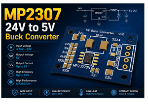 MP2307 5V to 24V Buck Converter
IntroductionIf you've ever needed to step down a higher DC voltage say, from a 12V or 24V source dow...
MP2307 5V to 24V Buck Converter
IntroductionIf you've ever needed to step down a higher DC voltage say, from a 12V or 24V source dow...
-
Programmable Mist Maker - XIAO / QT PY Extension
725 1 0 -
RadioHAT - Raspberry Pi radio development platform
564 0 1 -
-
-
-
-
ARPS-2 – Arduino-Compatible Robot Project Shield for Arduino UNO
3058 0 6 -
A Compact Charging Breakout Board For Waveshare ESP32-C3
3672 3 8 -
AI-driven LoRa & LLM-enabled Kiosk & Food Delivery System
3955 2 2


