


|
|
Espressif ESP32 Development Board |
x 2 | |
|
|
GC9A01 Round Display |
x 2 | |
|
|
1N4007TWGMC
|
x 2 | |
|
|
Resistor 10k ohm |
x 2 | |
|
|
Resistor 220 ohm |
x 2 | |
|
|
Resistor 220 ohm |
x 2 |

|
Soldering Iron Kit |
|

|
arduino IDEArduino
|
ESP32 Analog style VU meter with GC9A01 Round Dispalys + Peak Meters
A typical VU meter measures audio signals and displays them with a visual indicator. In the classic VU meter design is used a moving needle (actually a sensitive galvanometer) that points to a scale on a calibrated range.

The needle moves left or right depending on the strength of the audio signal. I recently acquired these small round TFT displays with a GC9A01 chip. Its basic purpose is for making smart watches, but in fact their shape is ideally suited for making a retro-look VU meter. My attention was drawn to a project on thesolaruniverse blog, which describes in detail how to create meters gauges and dials on this display with arduino nano.
For the needs of this project I made some modifications to the code but basically kept the beautiful retro design and colors. Now, instead of random values, the instrument shows the real values of the voltage applied to the input pin of the microcontroller. For a more homogeneous movement of the needle, I now use a more powerful ESP32 microcontroller.

This project is sponsored by PCBWay. This year, PCBWay is organizing the 11th badge design contest from March 3rd to April 31st. Follow the design requirements and Submit your designs in one of the given ways, and become the winner of one of the valuable prizes in cash and cupons. This contest is more than a competition—it’s a celebration of 11 years of innovation and a chance to dream about the boundless possibilities ahead with PCBWay.

Nowadays the price of ESP32 is very low, so for better separation of the channels I decided to use a separate microcontroller for each channel. In this project I also added a peak meter that signals the moment of exceeding the permitted level of the signal with an LED.
The device is very simple to make and consists of several components:
- ESP32 microcontroller - two pieces
- Two round displays with GC9A01 and 240x240 resolution
- envelope followers made with two small signal diodes and two capacitors
- and two leds with current limiting resistors

In particular, in this case I use the simplest passive envelope follower consisting of a diode and a capacitor, because the whole device is mainly intended as a demo device for testing, and based on this idea, a precise, fully functional audio VU meter can be made later with certain software and hardware modifications.
And now let's see how this VU meter works in real conditions.

Let me mention that a stereo potentiometer can be placed on the input in order to regulate the signal level, but for the sake of simplification I do it with the Windows mixer software.
And finally a short conclusion: This small, simple and interesting arduino project can be made in a few hours, and has a beautiful retro look, so you can use it as an additional part of any audio device, or as a stand-alone unit. With minimal code modification it can be used on many other devices (eg radio receiver) where signal strength measurement is required. The Vu meter is built in a suitable plastic box made of PVC material and lined with self-adhesive colored wallpaper.
// GCA901_Nano_voltage_meter
//
// grid voltage variation monitor (230V - 250V AC)
// rolling averaged voltage (of 10 readings) is sent to display
// NOTE: here voltage generated with random function
//
// microcontroller: Arduino Nano
// display 240*240 circular SPI 3.3V TFT with GC9A01 controller
//
// note: random function drives fluctuations of the parameter named 'volt'
// CG9A01    Arduino Nano
//  RST -------- NC
//  CST -------- 10
//  DC ---------  9
//  SDA -------- 11 - green wire
//  SCL -------- 13 - yellow wire
//
// Floris Wouterlood
// September 1, 2023
// public domain

// made for a 240*240 pixel circular display
// all x-y-coordinates relative to center = x = 120 and y = 120

   #include "SPI.h"
   #include "Adafruit_GFX.h"
   #include "Adafruit_GC9A01A.h"

   #define TFT_DC 2
   #define TFT_CS 15

   Adafruit_GC9A01A tft (TFT_CS, TFT_DC);

   #define BLACK      0x0000                                                               // some extra colors
   #define BLUE       0x001F
   #define RED        0xF800
   #define GREEN      0x07E0
   #define CYAN       0x07FF
   #define MAGENTA    0xF81F
   #define YELLOW     0xFFE0
   #define WHITE      0xFFFF
   #define ORANGE     0xFBE0
   #define GREY       0x84B5
   #define BORDEAUX   0xA000
   #define AFRICA     0xAB21                // 0xce5f  //0xAB21                                                               // current dial color
    const int vlez = 34;
   #define DEG2RAD 0.0174532925
   //int vlez;
   int sig = 0;
   int multiplier;
   int    frametime = 100;
   int    x_pos;
   int    y_pos;
   int    center_x = 120;                                                                  // center x of dial on 240*240 TFT display
   int    center_y = 120;                                                                  // center y of dial on 240*240 TFT display
   float  pivot_x, pivot_y,pivot_x_old, pivot_y_old;
   float  p1_x,p1_y,p2_x,p2_y,p3_x, p3_y, p4_x, p4_y, p5_x, p5_y;
   float  p1_x_old,p1_y_old, p2_x_old, p2_y_old, p3_x_old, p3_y_old;
   float  p4_x_old, p4_y_old, p5_x_old, p5_y_old;
   float  angleOffset = 3.14;
   float  arc_x;
   float  arc_y;
   int    radius = 120;                                                                    // center y of circular scale
   float  angle_circle = 0;
   float  needleAngle = 0;
   int    iteration = 0;
   int    j;
   float  volt = 220;
   int    needle_multiplier = 1;
   float  needle_setter;
 float currentNeedleValue = 230;  // Start with a base voltage or level
float needleSpeed = 10;         // Speed at which the needle returns to the left

                                                     // to start with

void setup() {

   //randomSeed (analogRead(0));
 pinMode(12, OUTPUT);


   pinMode(vlez, INPUT);
   tft.begin();
   Serial.begin (9600);
   Serial.println ("");
   Serial.println ("");
   tft.setRotation (0);

   tft.fillScreen (BLACK);
   tft.drawCircle (center_x, center_y,120, BLACK);
   pivot_x = center_x;
   pivot_y = center_y+50;

   p1_x_old = center_x; p1_y_old = center_y+50;
   p2_x_old = center_x; p2_y_old = center_y+50;
   p3_x_old = center_x; p3_y_old = center_y+50;
   p4_x_old = center_x; p4_y_old = center_y+50;
   p5_x_old = center_x; p5_y_old = center_y+30;

   create_dial ();
   needle_setter = volt;
   needleAngle = (((needle_setter)*DEG2RAD*1.8)-3.14);
   needle();
   draw_pivot ();
}


void loop (){

  // Map the analog input (voltage) to the needle range
  float targetNeedleValue = map(analogRead(vlez), 0, 400, 230, 270);
  Serial.println(targetNeedleValue);
  sig = analogRead(vlez);
  if (sig > 280)  {digitalWrite(12, HIGH);} else {digitalWrite(12, LOW);}


  // If the target value is greater than the current needle position, move quickly
  if (targetNeedleValue > currentNeedleValue) {
    currentNeedleValue = targetNeedleValue;
  }
  // If the target value is lower, move more slowly to simulate damping
  else if (targetNeedleValue < currentNeedleValue) {
    currentNeedleValue -= needleSpeed; // Decrease the value gradually
    if (currentNeedleValue < targetNeedleValue) {
      currentNeedleValue = targetNeedleValue;  // Ensure we don't overshoot
    }
  }

  // Update the needle position
  needle_setter = currentNeedleValue;
  needle();
  draw_pivot();

  delay(frametime);  // Control the update rate
}


void needle (){                                                                            // dynamic needle management

   tft.drawLine (pivot_x, pivot_y, p1_x_old, p1_y_old, AFRICA);                            // remove old needle
   tft.fillTriangle (p1_x_old, p1_y_old, p2_x_old, p2_y_old, p3_x_old, p3_y_old, AFRICA);  // remove old arrow head
   tft.fillTriangle (pivot_x, pivot_y, p4_x_old, p4_y_old, p5_x_old, p5_y_old, AFRICA);    // remove old arrow head

   needleAngle = (((needle_setter)*0.01745331*1.8)-3.14);
   p1_x = (pivot_x + ((radius)*cos(needleAngle)));                                         // needle tip
   p1_y = (pivot_y + ((radius)*sin(needleAngle)));

   p2_x = (pivot_x + ((radius-15)*cos(needleAngle-0.05)));                                 // needle triange left
   p2_y = (pivot_y + ((radius-15)*sin(needleAngle-0.05)));

   p3_x = (pivot_x + ((radius-15)*cos(needleAngle+0.05)));                                 // needle triange right
   p3_y = (pivot_y + ((radius-15)*sin(needleAngle+0.05)));

   p4_x = (pivot_x + ((radius-90)*cos(angleOffset+(needleAngle-0.2))));                    // needle triange left
   p4_y = (pivot_y + ((radius-90)*sin(angleOffset+(needleAngle-0.2))));

   p5_x = (pivot_x + ((radius-90)*cos(angleOffset+(needleAngle+0.2))));                    // needle triange right
   p5_y = (pivot_y + ((radius-90)*sin(angleOffset+(needleAngle+0.2))));

   p1_x_old = p1_x; p1_y_old = p1_y;                                                       // remember previous needle position
   p2_x_old = p2_x; p2_y_old = p2_y;
   p3_x_old = p3_x; p3_y_old = p3_y;

   p4_x_old = p4_x; p4_y_old = p4_y;                                                       // remember previous needle counterweight position
   p5_x_old = p5_x; p5_y_old = p5_y;

   tft.drawLine (pivot_x, pivot_y, p1_x, p1_y, BLACK);                                     // create needle
   tft.fillTriangle (p1_x, p1_y, p2_x, p2_y, p3_x, p3_y, BLACK);                           // create needle tip pointer
  // tft.drawLine (center_x-80, center_y+70, center_x+80,center_y+70, BLACK);                // repair floor
   tft.fillTriangle (pivot_x, pivot_y, p4_x, p4_y, p5_x, p5_y, BLACK);                     // create needle counterweight
}


void create_dial (){

   tft.fillCircle (center_x, center_y,120, AFRICA);                                        // general dial field
   tft.drawCircle (center_x, center_y,118,GREY);
   tft.drawCircle (center_x, center_y,117,BLACK);
   tft.drawCircle (center_x, center_y,116,BLACK);
   tft.drawCircle (center_x, center_y,115,GREY);

   for (j= 30; j<60    ; j+=5)
       {
        needleAngle = ((j*DEG2RAD*1.8)-3.14);
        arc_x = (pivot_x + ((radius+15)*cos(needleAngle)));                                // needle tip
        arc_y = (pivot_y + ((radius+15)*sin(needleAngle)));
        tft.drawPixel  (arc_x,arc_y, BLACK);
        tft.fillCircle (arc_x,arc_y,2, BLACK);
        }

   for (j= 60; j<75    ; j+=5)
       {
        needleAngle = ((j*DEG2RAD*1.8)-3.14);
        arc_x = (pivot_x + ((radius+15)*cos(needleAngle)));                                // needle tip
        arc_y = (pivot_y + ((radius+15)*sin(needleAngle)));
        tft.drawPixel  (arc_x,arc_y, RED);
        tft.fillCircle (arc_x,arc_y,2, RED);
        }

   tft.setTextColor (BLACK,AFRICA);
   tft.setTextSize (4);
   tft.setCursor (center_x+55, center_y+40);
   tft.print ("L");
      tft.setTextSize (4);
   tft.setCursor (center_x-70, center_y+40);
  tft.print ("VU");

  // tft.drawLine (center_x-80, center_y+70, center_x+80,center_y+70, WHITE);                // create floor
}


void draw_pivot (){

   tft.fillCircle (pivot_x, pivot_y,8,RED);
   tft.drawCircle (pivot_x, pivot_y,8,BLACK);
   tft.drawCircle (pivot_x, pivot_y,3,BLACK);
}
// GCA901_Nano_voltage_meter
//
// grid voltage variation monitor (230V - 250V AC)
// rolling averaged voltage (of 10 readings) is sent to display
// NOTE: here voltage generated with random function
//
// microcontroller: Arduino Nano
// display 240*240 circular SPI 3.3V TFT with GC9A01 controller
//
// note: random function drives fluctuations of the parameter named 'volt'
// CG9A01    Arduino Nano
//  RST -------- NC
//  CST -------- 10
//  DC ---------  9
//  SDA -------- 11 - green wire
//  SCL -------- 13 - yellow wire
//
// Floris Wouterlood
// September 1, 2023
// public domain

// made for a 240*240 pixel circular display
// all x-y-coordinates relative to center = x = 120 and y = 120

   #include "SPI.h"
   #include "Adafruit_GFX.h"
   #include "Adafruit_GC9A01A.h"

   #define TFT_DC 2
   #define TFT_CS 15

   Adafruit_GC9A01A tft (TFT_CS, TFT_DC);

   #define BLACK      0x0000                                                               // some extra colors
   #define BLUE       0x001F
   #define RED        0xF800
   #define GREEN      0x07E0
   #define CYAN       0x07FF
   #define MAGENTA    0xF81F
   #define YELLOW     0xFFE0
   #define WHITE      0xFFFF
   #define ORANGE     0xFBE0
   #define GREY       0x84B5
   #define BORDEAUX   0xA000
   #define AFRICA     0xAB21                // 0xce5f  //0xAB21                                                               // current dial color
    const int vlez = 34;
   #define DEG2RAD 0.0174532925
   //int vlez;
   int sig = 0;
   int multiplier;
   int    frametime = 100;
   int    x_pos;
   int    y_pos;
   int    center_x = 120;                                                                  // center x of dial on 240*240 TFT display
   int    center_y = 120;                                                                  // center y of dial on 240*240 TFT display
   float  pivot_x, pivot_y,pivot_x_old, pivot_y_old;
   float  p1_x,p1_y,p2_x,p2_y,p3_x, p3_y, p4_x, p4_y, p5_x, p5_y;
   float  p1_x_old,p1_y_old, p2_x_old, p2_y_old, p3_x_old, p3_y_old;
   float  p4_x_old, p4_y_old, p5_x_old, p5_y_old;
   float  angleOffset = 3.14;
   float  arc_x;
   float  arc_y;
   int    radius = 120;                                                                    // center y of circular scale
   float  angle_circle = 0;
   float  needleAngle = 0;
   int    iteration = 0;
   int    j;
   float  volt = 220;
   int    needle_multiplier = 1;
   float  needle_setter;
 float currentNeedleValue = 230;  // Start with a base voltage or level
float needleSpeed = 10;         // Speed at which the needle returns to the left

                                                     // to start with

void setup() {

   //randomSeed (analogRead(0));
 pinMode(12, OUTPUT);


   pinMode(vlez, INPUT);
   tft.begin();
   Serial.begin (9600);
   Serial.println ("");
   Serial.println ("");
   tft.setRotation (0);

   tft.fillScreen (BLACK);
   tft.drawCircle (center_x, center_y,120, BLACK);
   pivot_x = center_x;
   pivot_y = center_y+50;

   p1_x_old = center_x; p1_y_old = center_y+50;
   p2_x_old = center_x; p2_y_old = center_y+50;
   p3_x_old = center_x; p3_y_old = center_y+50;
   p4_x_old = center_x; p4_y_old = center_y+50;
   p5_x_old = center_x; p5_y_old = center_y+30;

   create_dial ();
   needle_setter = volt;
   needleAngle = (((needle_setter)*DEG2RAD*1.8)-3.14);
   needle();
   draw_pivot ();
}


void loop (){

  // Map the analog input (voltage) to the needle range
  float targetNeedleValue = map(analogRead(vlez), 0, 400, 230, 270);
  Serial.println(targetNeedleValue);
  sig = analogRead(vlez);
  if (sig > 280)  {digitalWrite(12, HIGH);} else {digitalWrite(12, LOW);}


  // If the target value is greater than the current needle position, move quickly
  if (targetNeedleValue > currentNeedleValue) {
    currentNeedleValue = targetNeedleValue;
  }
  // If the target value is lower, move more slowly to simulate damping
  else if (targetNeedleValue < currentNeedleValue) {
    currentNeedleValue -= needleSpeed; // Decrease the value gradually
    if (currentNeedleValue < targetNeedleValue) {
      currentNeedleValue = targetNeedleValue;  // Ensure we don't overshoot
    }
  }

  // Update the needle position
  needle_setter = currentNeedleValue;
  needle();
  draw_pivot();

  delay(frametime);  // Control the update rate
}


void needle (){                                                                            // dynamic needle management

   tft.drawLine (pivot_x, pivot_y, p1_x_old, p1_y_old, AFRICA);                            // remove old needle
   tft.fillTriangle (p1_x_old, p1_y_old, p2_x_old, p2_y_old, p3_x_old, p3_y_old, AFRICA);  // remove old arrow head
   tft.fillTriangle (pivot_x, pivot_y, p4_x_old, p4_y_old, p5_x_old, p5_y_old, AFRICA);    // remove old arrow head

   needleAngle = (((needle_setter)*0.01745331*1.8)-3.14);
   p1_x = (pivot_x + ((radius)*cos(needleAngle)));                                         // needle tip
   p1_y = (pivot_y + ((radius)*sin(needleAngle)));

   p2_x = (pivot_x + ((radius-15)*cos(needleAngle-0.05)));                                 // needle triange left
   p2_y = (pivot_y + ((radius-15)*sin(needleAngle-0.05)));

   p3_x = (pivot_x + ((radius-15)*cos(needleAngle+0.05)));                                 // needle triange right
   p3_y = (pivot_y + ((radius-15)*sin(needleAngle+0.05)));

   p4_x = (pivot_x + ((radius-90)*cos(angleOffset+(needleAngle-0.2))));                    // needle triange left
   p4_y = (pivot_y + ((radius-90)*sin(angleOffset+(needleAngle-0.2))));

   p5_x = (pivot_x + ((radius-90)*cos(angleOffset+(needleAngle+0.2))));                    // needle triange right
   p5_y = (pivot_y + ((radius-90)*sin(angleOffset+(needleAngle+0.2))));

   p1_x_old = p1_x; p1_y_old = p1_y;                                                       // remember previous needle position
   p2_x_old = p2_x; p2_y_old = p2_y;
   p3_x_old = p3_x; p3_y_old = p3_y;

   p4_x_old = p4_x; p4_y_old = p4_y;                                                       // remember previous needle counterweight position
   p5_x_old = p5_x; p5_y_old = p5_y;

   tft.drawLine (pivot_x, pivot_y, p1_x, p1_y, BLACK);                                     // create needle
   tft.fillTriangle (p1_x, p1_y, p2_x, p2_y, p3_x, p3_y, BLACK);                           // create needle tip pointer
  // tft.drawLine (center_x-80, center_y+70, center_x+80,center_y+70, BLACK);                // repair floor
   tft.fillTriangle (pivot_x, pivot_y, p4_x, p4_y, p5_x, p5_y, BLACK);                     // create needle counterweight
}


void create_dial (){

   tft.fillCircle (center_x, center_y,120, AFRICA);                                        // general dial field
   tft.drawCircle (center_x, center_y,118,GREY);
   tft.drawCircle (center_x, center_y,117,BLACK);
   tft.drawCircle (center_x, center_y,116,BLACK);
   tft.drawCircle (center_x, center_y,115,GREY);

   for (j= 30; j<60    ; j+=5)
       {
        needleAngle = ((j*DEG2RAD*1.8)-3.14);
        arc_x = (pivot_x + ((radius+15)*cos(needleAngle)));                                // needle tip
        arc_y = (pivot_y + ((radius+15)*sin(needleAngle)));
        tft.drawPixel  (arc_x,arc_y, BLACK);
        tft.fillCircle (arc_x,arc_y,2, BLACK);
        }

   for (j= 60; j<75    ; j+=5)
       {
        needleAngle = ((j*DEG2RAD*1.8)-3.14);
        arc_x = (pivot_x + ((radius+15)*cos(needleAngle)));                                // needle tip
        arc_y = (pivot_y + ((radius+15)*sin(needleAngle)));
        tft.drawPixel  (arc_x,arc_y, RED);
        tft.fillCircle (arc_x,arc_y,2, RED);
        }

   tft.setTextColor (BLACK,AFRICA);
   tft.setTextSize (4);
   tft.setCursor (center_x+40, center_y+40);
   tft.print ("VU");
      tft.setTextSize (4);
   tft.setCursor (center_x-60, center_y+40);
  tft.print ("R");

  // tft.drawLine (center_x-80, center_y+70, center_x+80,center_y+70, WHITE);                // create floor
}


void draw_pivot (){

   tft.fillCircle (pivot_x, pivot_y,8,RED);
   tft.drawCircle (pivot_x, pivot_y,8,BLACK);
   tft.drawCircle (pivot_x, pivot_y,3,BLACK);
}

ESP32 Analog style VU meter with GC9A01 Round Dispalys + Peak Meters


Raspberry Pi 5 7 Inch Touch Screen IPS 1024x600 HD LCD HDMI-compatible Display for RPI 4B 3B+ OPI 5 AIDA64 PC Secondary Screen(Without Speaker)
BUY NOW


- Comments(0)
- Likes(2)
More by Mirko Pavleski
-
 Arduino 3D Printed self Balancing Cube
Self-balancing devices are electronic devices that use sensors and motors to keep themselves balanc...
Arduino 3D Printed self Balancing Cube
Self-balancing devices are electronic devices that use sensors and motors to keep themselves balanc...
-
 DIY Miniature X-Ray Machine using a TV Vacuum Tube DY86
An X-ray machine (or radiograph) is a quick, painless medical test that produces images of the struc...
DIY Miniature X-Ray Machine using a TV Vacuum Tube DY86
An X-ray machine (or radiograph) is a quick, painless medical test that produces images of the struc...
-
 Simple SDR Receiver Using 2x NE612 - Dual Conversion, Superheterodyne (0.1–30 MHz)
SDR (Software Defined Radio) is a radio system in which most of the functions of a classic radio (f...
Simple SDR Receiver Using 2x NE612 - Dual Conversion, Superheterodyne (0.1–30 MHz)
SDR (Software Defined Radio) is a radio system in which most of the functions of a classic radio (f...
-
 DIY Vintage TV VU Meter with peak indicators
Some time ago in one of my projects I presented you a way to turn a black and white old mini TV int...
DIY Vintage TV VU Meter with peak indicators
Some time ago in one of my projects I presented you a way to turn a black and white old mini TV int...
-
 DIY Tesla Coil based Plasma Rife Machine
In several of my previous videos, I presented you with different ways to make a Rife Machine, from ...
DIY Tesla Coil based Plasma Rife Machine
In several of my previous videos, I presented you with different ways to make a Rife Machine, from ...
-
 ESP32 Analog VU Meter – Smooth Needle, Real Audio Response (DIY Build)
In several of my previous videos I have shown you how to make analog VU meters emulated on differen...
ESP32 Analog VU Meter – Smooth Needle, Real Audio Response (DIY Build)
In several of my previous videos I have shown you how to make analog VU meters emulated on differen...
-
 The Ultimate Smartphone VFO ESP32 & Si5351 Wireless Control
Variable frequency oscillators (VFOs) are commonly used in radio transmitters and receivers, especi...
The Ultimate Smartphone VFO ESP32 & Si5351 Wireless Control
Variable frequency oscillators (VFOs) are commonly used in radio transmitters and receivers, especi...
-
 DIY Shortwave Propagation Monitor - Measure Ionosphere Conditions
Shortwave Propagation is the way radio waves in the 3 to 30 MHz range travel from point A to point ...
DIY Shortwave Propagation Monitor - Measure Ionosphere Conditions
Shortwave Propagation is the way radio waves in the 3 to 30 MHz range travel from point A to point ...
-
 Professional grade Smart Lock with ESP32, BLE and Android App Control
An electronic codelock is a security device that grants access using a numerical sequence—a PIN cod...
Professional grade Smart Lock with ESP32, BLE and Android App Control
An electronic codelock is a security device that grants access using a numerical sequence—a PIN cod...
-
 Building a 3-Input Stereo ECC83 (12AX7) Tube Preamp
Some time ago I presented you a project for a 3W stereo tube amplifier with a GU32 output vacuum t...
Building a 3-Input Stereo ECC83 (12AX7) Tube Preamp
Some time ago I presented you a project for a 3W stereo tube amplifier with a GU32 output vacuum t...
-
 ESP32 Weather Dashboard with Satellite Maps and 16-day Weather Forecast
As you can see from my previous videos, besides Electronics, my fields of experimentation and proje...
ESP32 Weather Dashboard with Satellite Maps and 16-day Weather Forecast
As you can see from my previous videos, besides Electronics, my fields of experimentation and proje...
-
 Retro Analog VU Meter on Round dispalys (ESP32 and GC9A01)
Recently, in one of my previous videos I presented you a Retro VU Meter project on round displays ...
Retro Analog VU Meter on Round dispalys (ESP32 and GC9A01)
Recently, in one of my previous videos I presented you a Retro VU Meter project on round displays ...
-
 Ultimate 2-Player Reaction Timer with WS2812B LED Strips & Arduino
Arcade reaction game is a genre of play designed to test a player's physical response time and hand...
Ultimate 2-Player Reaction Timer with WS2812B LED Strips & Arduino
Arcade reaction game is a genre of play designed to test a player's physical response time and hand...
-
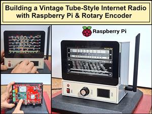 Building a Vintage Tube-Style Internet Radio with Raspberry Pi & Rotary Encoder
Internet radio (also known as web radio or net radio) is a digital audio service transmitted via th...
Building a Vintage Tube-Style Internet Radio with Raspberry Pi & Rotary Encoder
Internet radio (also known as web radio or net radio) is a digital audio service transmitted via th...
-
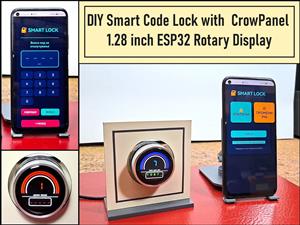 DIY Smart Code Lock with CrowPanel 1.28 ESP32 Rotary Display
A code lock is a keyless security device—either mechanical or electronic—that restricts access to d...
DIY Smart Code Lock with CrowPanel 1.28 ESP32 Rotary Display
A code lock is a keyless security device—either mechanical or electronic—that restricts access to d...
-
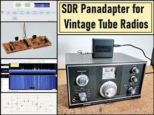 SDR Panadapter for Vintage Tube Radios – Step-by-Step Tutorial
A radio panadapter (or panoramic adapter) is a device or software tool used in amateur radio and ot...
SDR Panadapter for Vintage Tube Radios – Step-by-Step Tutorial
A radio panadapter (or panoramic adapter) is a device or software tool used in amateur radio and ot...
-
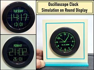 Oscilloscope Clock Simulation on a Round ESP32 Display
An oscilloscope clock is a circuit that turns an old analog oscilloscope into a stylish, retro-them...
Oscilloscope Clock Simulation on a Round ESP32 Display
An oscilloscope clock is a circuit that turns an old analog oscilloscope into a stylish, retro-them...
-
 DIY Simple GU32 Tube Stereo Amplifier (2x3W on 12VDC)
Vacuum tube amplifiers are often favored for their smooth harmonic distortion, especially in the low...
DIY Simple GU32 Tube Stereo Amplifier (2x3W on 12VDC)
Vacuum tube amplifiers are often favored for their smooth harmonic distortion, especially in the low...
-
Programmable Mist Maker - XIAO / QT PY Extension
180 0 0 -
RadioHAT - Raspberry Pi radio development platform
191 0 1 -
-
-
-
-
ARPS-2 – Arduino-Compatible Robot Project Shield for Arduino UNO
2768 0 5 -
A Compact Charging Breakout Board For Waveshare ESP32-C3
3276 3 8 -
AI-driven LoRa & LLM-enabled Kiosk & Food Delivery System
3535 2 2


