


|
|
LM741 Op-Amp (or TL071) |
x 1 | |
|
|
BC557 PNP Transistor |
x 1 | |
|
|
Potentiometer 1k |
x 1 | |
|
|
Potentiometer 10K |
x 1 | |
|
|
Search Coil |
x 1 | |
|
|
Passive Components (Resistors, Capacitors...) |
x 1 |

|
Soldering Iron Wire |
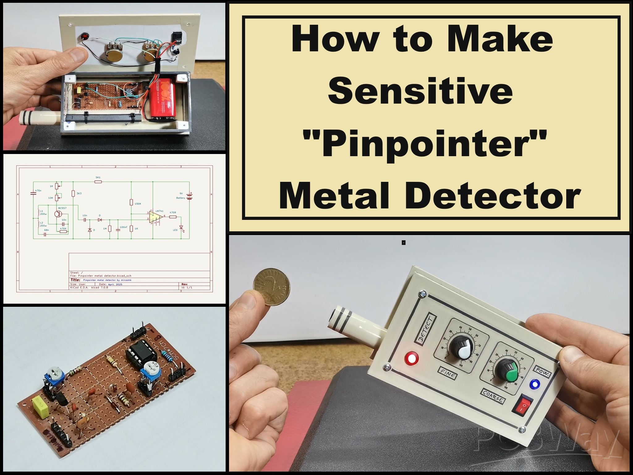
DIY Simple Sensitive Pinpointer Metal Detector
A pinpointer metal detector, often simply called a pinpointer, is a small, handheld device used to precisely locate metal targets that have already been detected in a general area by a larger, standard metal detector.
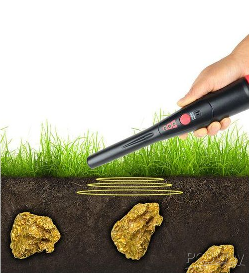
After a standard metal detector indicates a target and the user digs a hole or removes a plug of soil, the pinpointer is used to scan that small area. In one of my previous videos I presented a way to make a Pinpointer using an Arduino microcontroller board. This time I will present a very simple way to make such a device without the use of microcontrollers and programs, using only standard electronic components.
However, the sensitivity of this pinpointer is identical and even exceeds the previously mentioned one if properly adjusted. The difference is that there the device was adjusted only by pressing a button, while in this case we do it manually using a potentiometer.
This project is sponsored by PCBWay . They has all the services you need to create your project at the best price, whether is a scool project, or complex professional project. On PCBWay you can share your experiences, or get inspiration for your next project. They also provide completed Surface mount SMT PCB assemblY service at a best price, and ISO9001 quality control. Visit pcbway.com for more services.

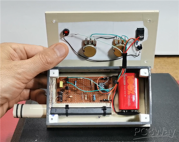
This pinpointer is very easy to make and consists of several standard electronic components that can be found in any average hardware store. These are:
- One universal PNP-type transistor (I use BC557 in this project)
- Two diodes of type 1N4148 or similar
- LM741 Operational amplifier (specifically I use TL081), and any other operational amplifier can be used
- LED for signaling
- Two potentiometers of 1K and 10K
- several capacitors and resistors
- And two coils wound next to each other, each of which has about 200 turns of varnished copper wire with a cross section of 0.2 to 0.3 mm. The coils are wound on a ferrite core from an old AM receiver.
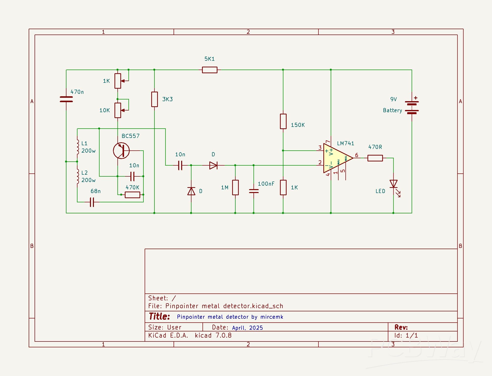
First, let me briefly explain the working principle. Part with the transistor and the two coils represents an oscillator with a frequency of about 20KHz. The amplitude of this sinusoidal signal can be changed in two ways. The first is by changing the value of this set of potentiometers, and the other is by bringing a metal object closer to the ferrite core on which the two coils are wound. In the second way, by bringing the metal closer, the amplitude of the signal decreases.
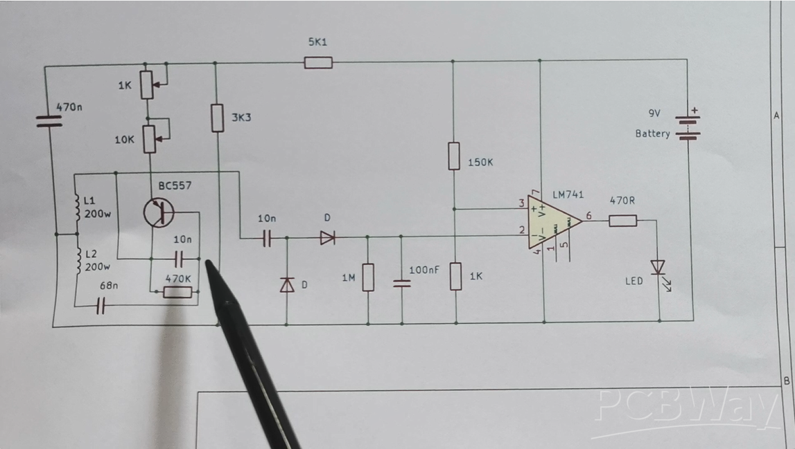
Then comes a rectifier with two diodes and a capacitor, and so the rectified voltage is brought to the inverting input of the operational amplifier. On the non-inverting input, using this voltage divider, we bring a voltage close to that of the inverting input. Now with these two potentiometers we adjust the voltage on pin 2 to be just a little higher than that on pin 3 and the LED goes out. Now, as the metal object approaches the coils, the amplitude of the sine signal decreases, and so does the voltage at pin 2, so when this voltage becomes lower than that at pin 3, a voltage appears at output 6 and the LED lights up, which actually indicates the presence of metal near the coils. Let's see how this practically looks on an oscilloscope.
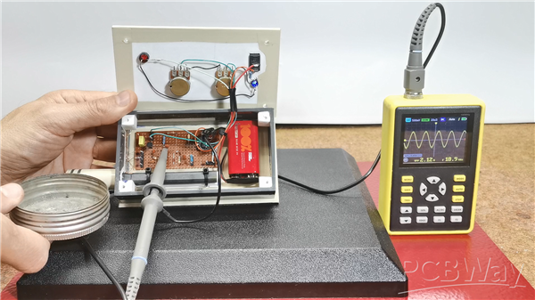
The oscilloscope is connected to the output of the oscillator to see its properties. We see the signal from the oscillator. With the potentiometers we change its amplitude. Now the amplitude is constant, but if we bring a metal object closer to the coils we see that it decreases proportionally. It is this property that we use for detection. Now let's see how this device behaves in real conditions on metal objects with different dimensions, i.e. its sensitivity. Just to mention that this sensor is sensitive to temperature changes, so it is necessary to adjust the potentiometers more often to get the highest sensitivity.
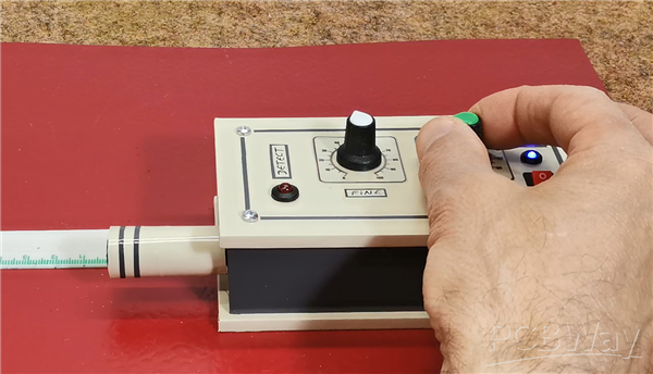
After turning on the detector, we move the coarse adjustment potentiometer until the LED goes out. Then, with the FINE potentiometer, we adjust the threshold more precisely just before the LED lights up. At this point, the metal detector is ready.
The advantage of the aforementioned pinpointer with an Arduino microcontroller is that this adjustment is faster and simpler, and is achieved with a short press of a button.
And finally, a short conclusion. This is an extremely simple pinpoint metal detector that, although made only with standard electronic components, has quite satisfactory sensitivity, detecting a small coin at a distance of 4-5 cm, and a larger object at 7-8 cm and more.
DIY Simple Sensitive Pinpointer Metal Detector


Raspberry Pi 5 7 Inch Touch Screen IPS 1024x600 HD LCD HDMI-compatible Display for RPI 4B 3B+ OPI 5 AIDA64 PC Secondary Screen(Without Speaker)
BUY NOW


- Comments(0)
- Likes(1)
More by Mirko Pavleski
-
 Arduino 3D Printed self Balancing Cube
Self-balancing devices are electronic devices that use sensors and motors to keep themselves balanc...
Arduino 3D Printed self Balancing Cube
Self-balancing devices are electronic devices that use sensors and motors to keep themselves balanc...
-
 Elecrow All-in-One Arduino Starter Kit Review - 20 Projects & 16 Modules
This time I will describe a simple and practical way to enter the world of microcontrollers, specif...
Elecrow All-in-One Arduino Starter Kit Review - 20 Projects & 16 Modules
This time I will describe a simple and practical way to enter the world of microcontrollers, specif...
-
 ESP32-C3 Color Detector with TCS34725, Real-Time RGB Detection & Web Interface
Color detection is a fundamental task in many embedded systems – from industrial sorting machines t...
ESP32-C3 Color Detector with TCS34725, Real-Time RGB Detection & Web Interface
Color detection is a fundamental task in many embedded systems – from industrial sorting machines t...
-
 DIY ESP32 Telegram Flood Protection System - Smart Home Automation
Recently I had an unpleasant experience in my home, specifically my ground floor was flooded as a r...
DIY ESP32 Telegram Flood Protection System - Smart Home Automation
Recently I had an unpleasant experience in my home, specifically my ground floor was flooded as a r...
-
 Real-Time Air Traffic Radar using ESP32 + ADS-B Data
ADS-B, which stands for Automatic Dependent Surveillance-Broadcast, is the modern standard for trac...
Real-Time Air Traffic Radar using ESP32 + ADS-B Data
ADS-B, which stands for Automatic Dependent Surveillance-Broadcast, is the modern standard for trac...
-
 DIY Green Laser Night Sky Object Finder - Find Stars & Galaxies Instantly with great accuracy
As an amateur astronomer, especially at the beginning, the most difficult part of observing the nig...
DIY Green Laser Night Sky Object Finder - Find Stars & Galaxies Instantly with great accuracy
As an amateur astronomer, especially at the beginning, the most difficult part of observing the nig...
-
 DIY Avionics Simulator with ESP32 - Artificial Horizon, Compass & Altimeter
The inspiration for this project comes from classical aircraft cockpit instruments used for navigat...
DIY Avionics Simulator with ESP32 - Artificial Horizon, Compass & Altimeter
The inspiration for this project comes from classical aircraft cockpit instruments used for navigat...
-
 DIY Miniature X-Ray Machine using a TV Vacuum Tube DY86
An X-ray machine (or radiograph) is a quick, painless medical test that produces images of the struc...
DIY Miniature X-Ray Machine using a TV Vacuum Tube DY86
An X-ray machine (or radiograph) is a quick, painless medical test that produces images of the struc...
-
 Simple SDR Receiver Using 2x NE612 - Dual Conversion, Superheterodyne (0.1–30 MHz)
SDR (Software Defined Radio) is a radio system in which most of the functions of a classic radio (f...
Simple SDR Receiver Using 2x NE612 - Dual Conversion, Superheterodyne (0.1–30 MHz)
SDR (Software Defined Radio) is a radio system in which most of the functions of a classic radio (f...
-
 DIY Vintage TV VU Meter with peak indicators
Some time ago in one of my projects I presented you a way to turn a black and white old mini TV int...
DIY Vintage TV VU Meter with peak indicators
Some time ago in one of my projects I presented you a way to turn a black and white old mini TV int...
-
 DIY Tesla Coil based Plasma Rife Machine
In several of my previous videos, I presented you with different ways to make a Rife Machine, from ...
DIY Tesla Coil based Plasma Rife Machine
In several of my previous videos, I presented you with different ways to make a Rife Machine, from ...
-
 ESP32 Analog VU Meter – Smooth Needle, Real Audio Response (DIY Build)
In several of my previous videos I have shown you how to make analog VU meters emulated on differen...
ESP32 Analog VU Meter – Smooth Needle, Real Audio Response (DIY Build)
In several of my previous videos I have shown you how to make analog VU meters emulated on differen...
-
 The Ultimate Smartphone VFO ESP32 & Si5351 Wireless Control
Variable frequency oscillators (VFOs) are commonly used in radio transmitters and receivers, especi...
The Ultimate Smartphone VFO ESP32 & Si5351 Wireless Control
Variable frequency oscillators (VFOs) are commonly used in radio transmitters and receivers, especi...
-
 DIY Shortwave Propagation Monitor - Measure Ionosphere Conditions
Shortwave Propagation is the way radio waves in the 3 to 30 MHz range travel from point A to point ...
DIY Shortwave Propagation Monitor - Measure Ionosphere Conditions
Shortwave Propagation is the way radio waves in the 3 to 30 MHz range travel from point A to point ...
-
 Professional grade Smart Lock with ESP32, BLE and Android App Control
An electronic codelock is a security device that grants access using a numerical sequence—a PIN cod...
Professional grade Smart Lock with ESP32, BLE and Android App Control
An electronic codelock is a security device that grants access using a numerical sequence—a PIN cod...
-
 Building a 3-Input Stereo ECC83 (12AX7) Tube Preamp
Some time ago I presented you a project for a 3W stereo tube amplifier with a GU32 output vacuum t...
Building a 3-Input Stereo ECC83 (12AX7) Tube Preamp
Some time ago I presented you a project for a 3W stereo tube amplifier with a GU32 output vacuum t...
-
 ESP32 Weather Dashboard with Satellite Maps and 16-day Weather Forecast
As you can see from my previous videos, besides Electronics, my fields of experimentation and proje...
ESP32 Weather Dashboard with Satellite Maps and 16-day Weather Forecast
As you can see from my previous videos, besides Electronics, my fields of experimentation and proje...
-
 Retro Analog VU Meter on Round dispalys (ESP32 and GC9A01)
Recently, in one of my previous videos I presented you a Retro VU Meter project on round displays ...
Retro Analog VU Meter on Round dispalys (ESP32 and GC9A01)
Recently, in one of my previous videos I presented you a Retro VU Meter project on round displays ...
-
Programmable Mist Maker - XIAO / QT PY Extension
1140 2 1 -
RadioHAT - Raspberry Pi radio development platform
951 0 2 -
-
-
-
-
ARPS-2 – Arduino-Compatible Robot Project Shield for Arduino UNO
3376 0 6 -
A Compact Charging Breakout Board For Waveshare ESP32-C3
3992 3 8 -
AI-driven LoRa & LLM-enabled Kiosk & Food Delivery System
4379 2 2


