


|
Soldering Iron Kit |
DIY Lakhovsky MWO (Milti Wave Oscollator) device, detailed informations, facts, analysis
Georges Lakhovsky (1869–1942) was a Russian scientist, philosopher, and inventor who lived in the early 20th century. He is best known for his work on the Multiple Wave Oscillator, a device he claimed could cure diseases such as cancer by exposing cells to a combination of radio frequencies. While his ideas and theories have been widely discredited and are not supported by mainstream science, some people continue to use his work as a basis for alternative medical treatments.
Other benefits according to his claim are:
- Cell revitalization by increasing the oxygen supply and the nutritional value of the blood,
- Activation of the body's self-healing powers and increase of the general well-being
- Pain therapy
- Detoxification and elimination of harmful substances
- Autoimmune Disease, and other conditions
Lakhovsky's machine worked on a different angle or principle to Rife's. It did not attack the microbes directly, but reinforced the vitality of the organism by accelerating cellular oscillation. It was intended to revitalise the oscillations of your normally healthy cells. It was therefor the reinforced organism that successfully resists the microbes and all pathogenic causes. The machine discharged high voltage that gives off electromagnetic pulses with an emphasis on producing the greatest number or widest range of frequencies/harmonics as possible, but it cannot maintain 1 steady frequency which was what Rife was doing to resonate a microbe to death.
The Multiple Wave Oscillator machine generally consists of two parts :
- high voltage and high frequency impulses generator, usually a Tesla coil.
- and other part is a specially designed antenna,

The first part is the Tesla transformer, which at that time was of the spark gap type, but in this case I will use a super simple single Mosfet Tesla Transformer, because it is simpler to make and performs the same function. The way you can make such a Tesla coil is described in one of my previous videos. (https://www.youtube.com/watch?v=Q1M2VBvOzLA)
The oscillation frequency of this type of transformer(Tesla coil) is in the range of several 100 kHz to a few MHz. According to Lakovski, the unit should emit electromagnetic radiation in a much wider range, from 1 Hertz to 300 Gigahertz at the fundamental, along with many harmonics and sub-harmonics. It is allegedly achieved with the help of a specially designed antenna consisting of concentric rings forming electrical dipole antennas having capacitive gaps opposing each other by 180° (called Lakhovsky antennas).
Just to mention that my antenna is made according to Lakhovski's original drawings.

In this experiment, I will try to examine the claims from a technical point of view. For this purpose I will use SDRplay Software Defined Radio with apropriate spectrum analyzer software SDRuno. The frequency range of the Spectrum Analyzer in thi scase ranges from a few kilohertz up to about 2 Gigahertz, which is quite enough to check if the device has the features described previously. The small antenna on the SDR receiver serves to receive the signals emitted by the device.

Around the middle of the video you can see the Amplitude 0 - the frequency characteristic of the Tesla coil itself, as well as the Tesla coil together with the famous Lakhovsky antenna, in all frequency ranges where the signal could be detected.
And now finally, a short conclusion:
First of all, let me mention that the measurements in this experiment are approximate and simplified, all in order to be more understandable for a more people. In addition, I am not a medical person and I will not make comments in that area, but only analyze the technical side. Unlike the Rife machine, which in a technical sense is completely functional, here the result is very different. Lakhovski's claim is that the antenna radiates a whole spectrum in the area of one Hertz, up to 30 GHz. As can be seen from the measurements, the radiation range of the Tesla transformer itself is up to 50MHz, and with the specially designed antenna, with a very weak intensity up to 300 and 500 Megahertz, which is very far from the previously mentioned 30 Gigahertz.
The lectures on the videos that can be found on the internet on this subject are very convincing and impressive, but there is nowhere to be found a video proving this theoretical claim. I would like it if someone came across such a video to send a link, because I am almost sure that those who believe in the functionality of this device will claim that I am wrong somewhere in the testing and presentation of the results.

Next, let me clarify the original picture where Lakovski is sitting on a chair between two antennas. The second antenna has absolutely no meaning in terms of the value of the frequencies that are radiated, but it just resonates at the same frequency as the transmitting antenna (source), and in fact the whole setup represents a wireless energy transfer device, as I described in one of my previous videos. (https://www.youtube.com/watch?v=R85IPpmHWMU&t=9s). I want to say that the two antennas, unlike one, in a certain way only extend the radiation of the electromagnetic field.
In general, this invention of Lakovsky is an ordinary tesla coil, which instead of a toroidal topload, has a so-called Lakovsky antenna, which, by the way, according to my observations slightly amplifies the field in front of it and somewhat increases the emitted frequency, thanks to the lower capacitance of the antenna, which is quite natural and nothing new. Unfortunately, there are many "experts" who, with the help of this and similar devices, "cure" all kinds of diseases, for which today's modern medicine has no cure. I can't even believe that some people sell at high prices small PCBs with a pattern in the form of the Lakovsky antenna and claim that these, and similar gadgets have a positive effect on the immune system and human health.

DIY Lakhovsky MWO (Milti Wave Oscollator) device, detailed informations, facts, analysis


Raspberry Pi 5 7 Inch Touch Screen IPS 1024x600 HD LCD HDMI-compatible Display for RPI 4B 3B+ OPI 5 AIDA64 PC Secondary Screen(Without Speaker)
BUY NOW


- Comments(5)
- Likes(1)
More by Mirko Pavleski
-
 Arduino 3D Printed self Balancing Cube
Self-balancing devices are electronic devices that use sensors and motors to keep themselves balanc...
Arduino 3D Printed self Balancing Cube
Self-balancing devices are electronic devices that use sensors and motors to keep themselves balanc...
-
 Simple SDR Receiver Using 2x NE612 - Dual Conversion, Superheterodyne (0.1–30 MHz)
SDR (Software Defined Radio) is a radio system in which most of the functions of a classic radio (f...
Simple SDR Receiver Using 2x NE612 - Dual Conversion, Superheterodyne (0.1–30 MHz)
SDR (Software Defined Radio) is a radio system in which most of the functions of a classic radio (f...
-
 DIY Vintage TV VU Meter with peak indicators
Some time ago in one of my projects I presented you a way to turn a black and white old mini TV int...
DIY Vintage TV VU Meter with peak indicators
Some time ago in one of my projects I presented you a way to turn a black and white old mini TV int...
-
 DIY Tesla Coil based Plasma Rife Machine
In several of my previous videos, I presented you with different ways to make a Rife Machine, from ...
DIY Tesla Coil based Plasma Rife Machine
In several of my previous videos, I presented you with different ways to make a Rife Machine, from ...
-
 ESP32 Analog VU Meter – Smooth Needle, Real Audio Response (DIY Build)
In several of my previous videos I have shown you how to make analog VU meters emulated on differen...
ESP32 Analog VU Meter – Smooth Needle, Real Audio Response (DIY Build)
In several of my previous videos I have shown you how to make analog VU meters emulated on differen...
-
 The Ultimate Smartphone VFO ESP32 & Si5351 Wireless Control
Variable frequency oscillators (VFOs) are commonly used in radio transmitters and receivers, especi...
The Ultimate Smartphone VFO ESP32 & Si5351 Wireless Control
Variable frequency oscillators (VFOs) are commonly used in radio transmitters and receivers, especi...
-
 DIY Shortwave Propagation Monitor - Measure Ionosphere Conditions
Shortwave Propagation is the way radio waves in the 3 to 30 MHz range travel from point A to point ...
DIY Shortwave Propagation Monitor - Measure Ionosphere Conditions
Shortwave Propagation is the way radio waves in the 3 to 30 MHz range travel from point A to point ...
-
 Professional grade Smart Lock with ESP32, BLE and Android App Control
An electronic codelock is a security device that grants access using a numerical sequence—a PIN cod...
Professional grade Smart Lock with ESP32, BLE and Android App Control
An electronic codelock is a security device that grants access using a numerical sequence—a PIN cod...
-
 Building a 3-Input Stereo ECC83 (12AX7) Tube Preamp
Some time ago I presented you a project for a 3W stereo tube amplifier with a GU32 output vacuum t...
Building a 3-Input Stereo ECC83 (12AX7) Tube Preamp
Some time ago I presented you a project for a 3W stereo tube amplifier with a GU32 output vacuum t...
-
 ESP32 Weather Dashboard with Satellite Maps and 16-day Weather Forecast
As you can see from my previous videos, besides Electronics, my fields of experimentation and proje...
ESP32 Weather Dashboard with Satellite Maps and 16-day Weather Forecast
As you can see from my previous videos, besides Electronics, my fields of experimentation and proje...
-
 Retro Analog VU Meter on Round dispalys (ESP32 and GC9A01)
Recently, in one of my previous videos I presented you a Retro VU Meter project on round displays ...
Retro Analog VU Meter on Round dispalys (ESP32 and GC9A01)
Recently, in one of my previous videos I presented you a Retro VU Meter project on round displays ...
-
 Ultimate 2-Player Reaction Timer with WS2812B LED Strips & Arduino
Arcade reaction game is a genre of play designed to test a player's physical response time and hand...
Ultimate 2-Player Reaction Timer with WS2812B LED Strips & Arduino
Arcade reaction game is a genre of play designed to test a player's physical response time and hand...
-
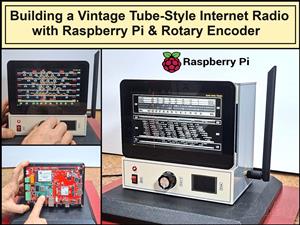 Building a Vintage Tube-Style Internet Radio with Raspberry Pi & Rotary Encoder
Internet radio (also known as web radio or net radio) is a digital audio service transmitted via th...
Building a Vintage Tube-Style Internet Radio with Raspberry Pi & Rotary Encoder
Internet radio (also known as web radio or net radio) is a digital audio service transmitted via th...
-
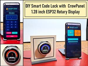 DIY Smart Code Lock with CrowPanel 1.28 ESP32 Rotary Display
A code lock is a keyless security device—either mechanical or electronic—that restricts access to d...
DIY Smart Code Lock with CrowPanel 1.28 ESP32 Rotary Display
A code lock is a keyless security device—either mechanical or electronic—that restricts access to d...
-
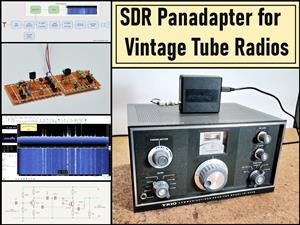 SDR Panadapter for Vintage Tube Radios – Step-by-Step Tutorial
A radio panadapter (or panoramic adapter) is a device or software tool used in amateur radio and ot...
SDR Panadapter for Vintage Tube Radios – Step-by-Step Tutorial
A radio panadapter (or panoramic adapter) is a device or software tool used in amateur radio and ot...
-
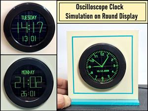 Oscilloscope Clock Simulation on a Round ESP32 Display
An oscilloscope clock is a circuit that turns an old analog oscilloscope into a stylish, retro-them...
Oscilloscope Clock Simulation on a Round ESP32 Display
An oscilloscope clock is a circuit that turns an old analog oscilloscope into a stylish, retro-them...
-
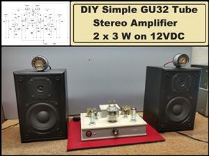 DIY Simple GU32 Tube Stereo Amplifier (2x3W on 12VDC)
Vacuum tube amplifiers are often favored for their smooth harmonic distortion, especially in the low...
DIY Simple GU32 Tube Stereo Amplifier (2x3W on 12VDC)
Vacuum tube amplifiers are often favored for their smooth harmonic distortion, especially in the low...
-
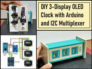 DIY 3-Display OLED Clock with Arduino and I2C Multiplexer
In this video I want to present you another unusual clock to add to my large collection of such DIY...
DIY 3-Display OLED Clock with Arduino and I2C Multiplexer
In this video I want to present you another unusual clock to add to my large collection of such DIY...
-
-
ARPS-2 – Arduino-Compatible Robot Project Shield for Arduino UNO
2598 0 5 -
A Compact Charging Breakout Board For Waveshare ESP32-C3
3062 3 8 -
AI-driven LoRa & LLM-enabled Kiosk & Food Delivery System
3285 2 1 -
-
-
-
ESP32-C3 BLE Keyboard - Battery Powered with USB-C Charging
3364 0 2


