


"perpetual" motion ball
Browsing internet and youtube, I found this mind blowing "perpetual motion" device designed by William Le
So I wanted to build mine :-)
Unfortunately the design is "commercial" (which I respect when seeing the quality of these jewels)
Wiiliam produced a transparent version showing the bowels but with no details...
And thanks to this it was quite easy to design my version !
Basic principle
- When the ball is falling, it passes very close to an inductive sensor which will "detect the ball" and trigger a coil gun to amplify motion
- the coil gun has to be controlled in "shot duration" to deliver enough but not too much energy to the ball
So the motion is "perpetual" provided that the Li Ion battery is not empty !
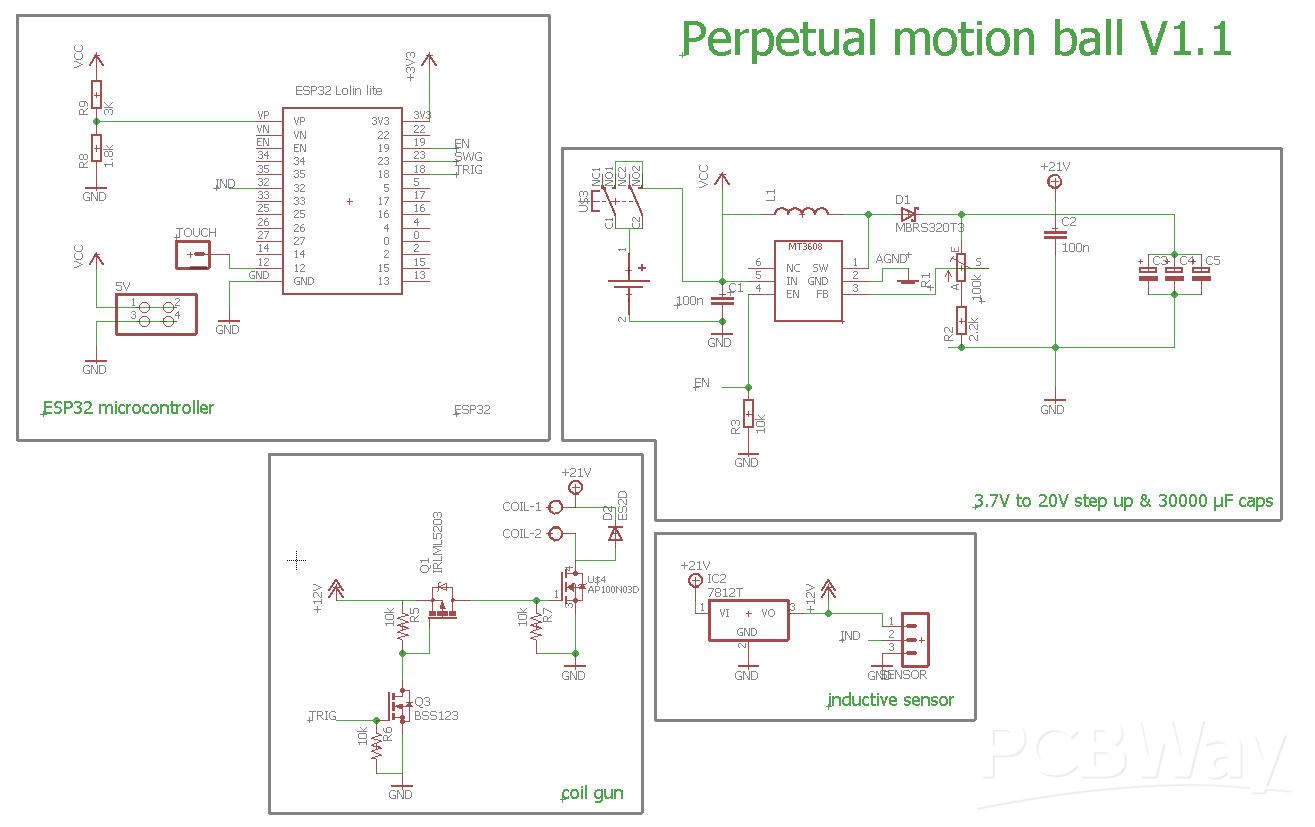
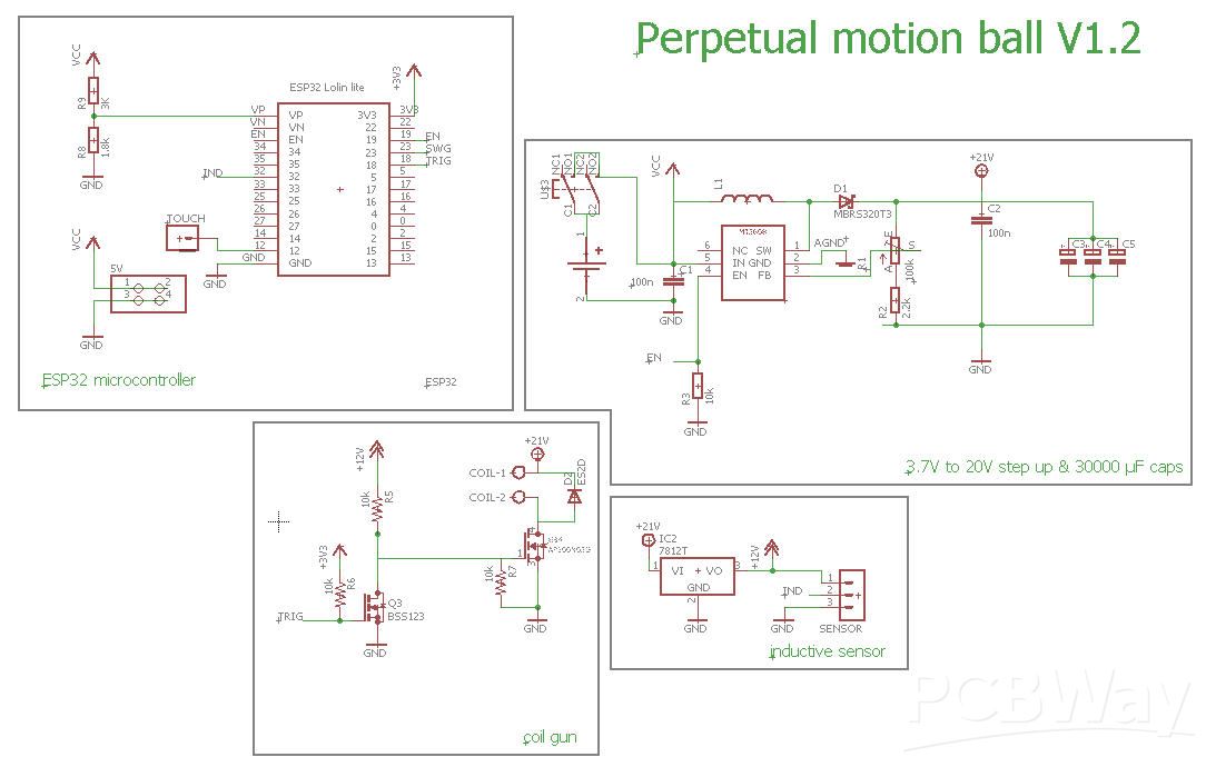
Schematics

Schematics is composed of 4 parts
- an ESP32 microcontroller to control the device
- a step up DC/DC converter to deliver power to the coil gun
- an inductive sensor to detect the ball
- the coil gun triggering mechanism
power
A single Li Ion 18650 battery will power the system.
This battery can directly power the ESP32 but is not "enough" to power the inductive sensor nor the coil Gun
A step Up DC/DC converter is used to boost the voltage up to 20-30V. A MT3608 is the chip used for the booster

Wiring of this chip uses the datasheet recommended circuit.
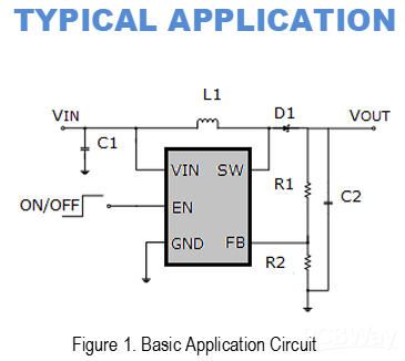
The enable pin4 will allow to disable the booster to save power. However, even when disabled, the VCC (battery voltage) will go on flowing into the L1 inductor to the ground (AGND)... So to preserve the battery we have to cut the ground using U$5 N channel Mosfet, itself triggered by the ESP32 via the SWG signal.
This trick allows to totally disconnect the step up and the coil gun when the ESP32 will go into deepsleep.
Note also that a bi stable switch (U$3) is used to cut the battery power (for long term storage). This switch will be hidden into the bottom box of the system and will not be visible from outside (apart a tiny hole allowing to switch On/off with a needle or a pin).
So for the rest of the schematics the ground (GND) can be cut and the "working ground" will be the AGND one.
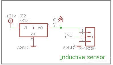
inductive sensor
The inductive sensor I have selected is a TL_W5MC1
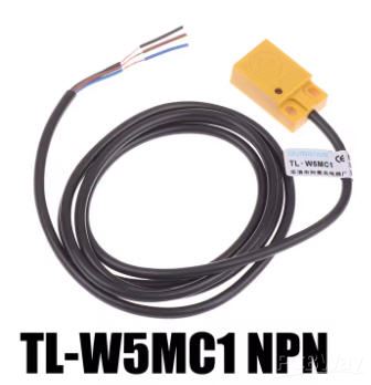
- it will detect metallic part at 5mm above its top side.
- It can be interfaced to a micro controller via an Open Collector NPN transistor.
- It should be powered at 12V to maximise the detection distance
This exact model can be interfaced to the ESP32 on a GPIO pin with internal pullup enabled.
Don't choose any other model with sensor pin internally tied to the positive wire...
So this sensor will be powered via an LM7812 voltage regulator
Beware also that my sensor was delivered with a nice sticker with wrong colors...
Working colors for the wires are:
- brown: positive rail (12V)
- black: sensor (IND)
- blue: ground (AGND)
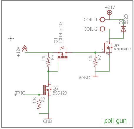
Coil Gun
The coil Gun is mostly composed of ... a coil !
It's a 50 mm diameter electromagnet with a 30mm iron core
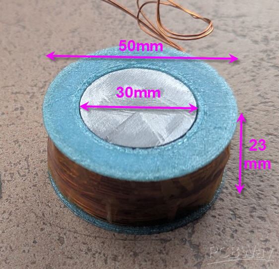
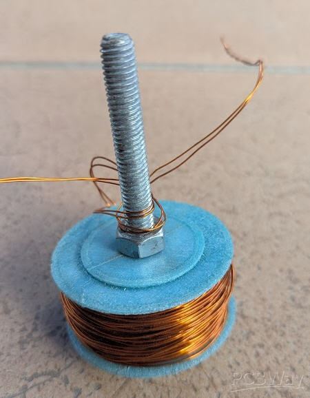
It has been wound with two strands of AWG22 enamel copper wires (I had this available...) but you'd better use a single AWG18 wire.
3d printed parts + 8mm M8 hex nut may help to fix the coil into a drill press for winding (see Printables link)
Going back to the schematics, we need now to trigger this coil gun !
3 big 10000 µF capacitors are connected in parallel and act as a power tank for the coil gun. They are charged at 20 to 30V (adjustable) by the step up booster.
Discharge is triggered by the ESP32 (TRIG pin) it switches a N channel mosfet Q3 which switches a P channel one (Q1) which releases the shot via U$4 N channel big mosfet.
This 3 stages triggering is needed as TRIG signal is at 3.3V, while U$4 must have a high enough gate voltage (12V) and AGND is already above the GND level (see above) so a P channel mosfet is needed to cut the positive side !
Micro controller
An ESP32 Wemos Lolin32 Lite microcontroller is used as the heart of the system.
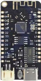
This board is tiny and cheap and has several interresting features:
- ESP32 can go into deepsleep mode preventing to drain the battery
- ESP32 has capacitive GPIO pins allowing to hide a touch pad into the body of the device
- this breadboard is equiped with a Li-Ion battery charger via USB
how all this works ?
Here is in a few words how this circuittry is finaly working:
Charging Phase: The circuit begins by charging the capacitor bank. The 3.7V Li-ion battery powers the MT3608 boost converter, which steps up the voltage to 20-30V. This voltage charges the large capacitor bank (30000µF or more). The capacitor stores the 10+ Joules of energy needed to launch the ball 10cm high.
Sensing and Timing: The steel ball moves along its path. As it reaches the ideal position for the launch, it passes by the inductive sensor. This sensor detects the ball's presence without any physical contact.
Triggering the Launch: The inductive sensor triggers an interrupt on the IND GPIO pin of the ESP32 which triggers the shot
The Powerful Pulse: The capacitor bank discharges a massive current pulse through the electromagnet. The electromagnet concentrates the magnetic field in a small, powerful area, which efficiently pulls and then launches the steel ball in the up direction.
Recharge and Repeat: After the pulse, the MOSFET turns off. The boost converter immediately begins recharging the capacitor bank for the next launch, and the cycle repeats.
Deep sleep: when no longer in use (no detection of the ball after xx seconds), the ESP32 will shutdown the Enable pin of the boost converter, switch off the negative rail and go into deepsleep mode. This allows to preserve the battery life during weeks
wakeup : simply touching the "TOUCH" pin will wake up the ESP32 and restart the process to the charging phase
battery safety: battery voltage is permanently monitored, so that the ESP32 will go to deep sleep when voltage becomes too low.
battery charge: simply connect the USB plug of the ESP32 to a smartphone charger and wait for the charging light to switch off
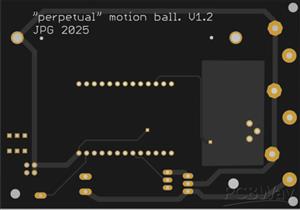
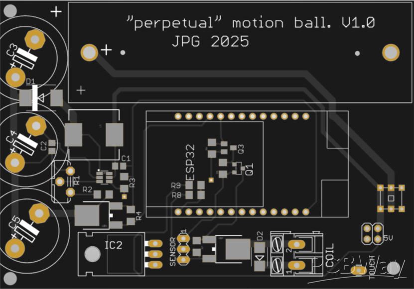
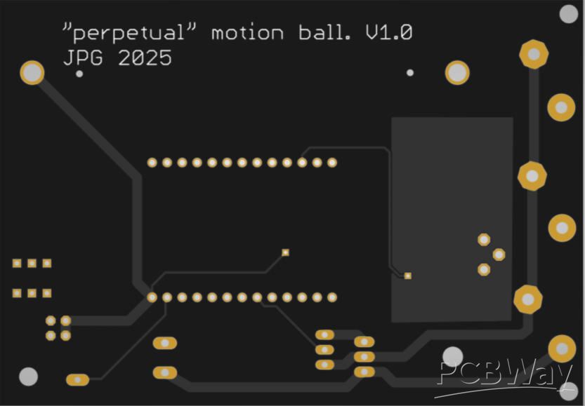
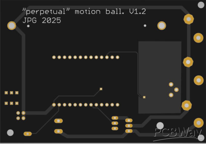
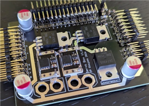
PCB
PCB has kindly been sponsored by PCBWay and is available directly on this project page.
As usual, quality is excellent and the PCB is very professional looking.
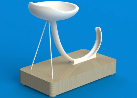
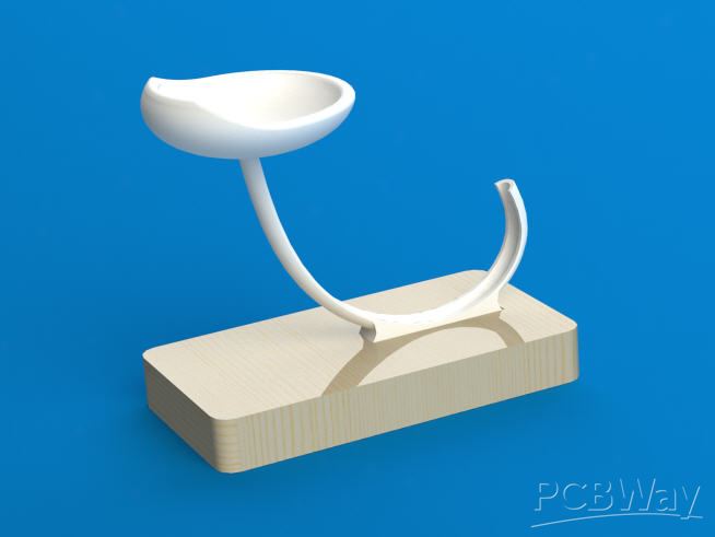
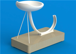
Enclosure and ball rail
I will use a 13mm iron ball.
This ball will fall from the top plate, follow a rail, have to go just on top of the inductive sensor and then be attracted (strongly) by the electromagnet to get cinetic energy.
Neglecting the air viscosity and assuming a perfect motion, the ball will follow a perfect parabola.
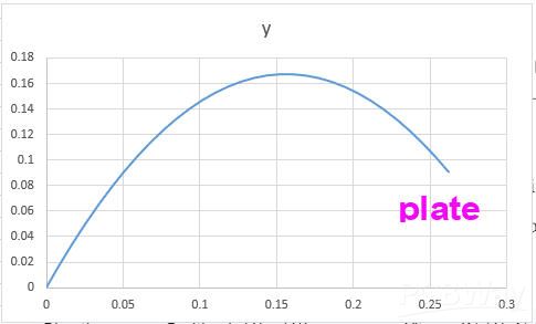
It will have to climb roughly 10cm to reach the plate.
The angle of the rail when the ball will take off is following this theoritical parabola !
A 3d printed plate + rail is available on the "printables.com" project. You can print the plate and the rail into two parts without supports. Then glue them with epoxy before sanding and fixing all this into the bottom enclosure.
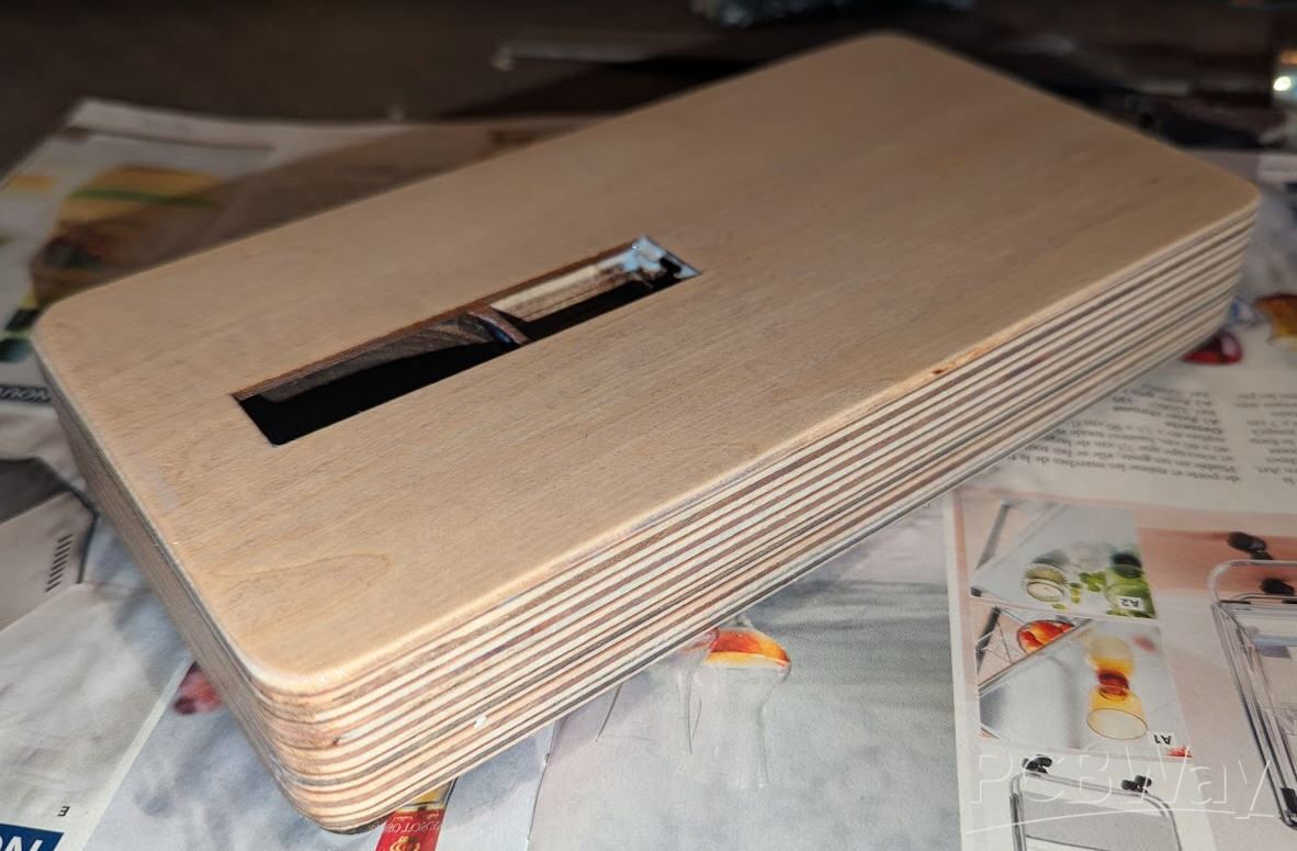
Alternatively you can laser cut the box using 3mm and 5mm plywood sheets. (use “boxLaserCut_dxf” file)
Don't forget to insert the 4 x M3 hex nuts used to fix the bottom before gluing the sheets or during 3D printing time… Small wood washers should be glued above the screws head to act as “feet”.
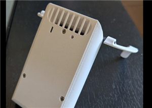
Here is the result after gluing, sanding and varnishing :
First tests after soldering
PCB was easily soldered and I could start testing the schematics...
Everything was ok until I inserted the battery into its connector. Then electronics smoke occured... The boost conveter chip MT3608 died and almost burnt...
I soldered a new one... same problem....
So I started to suspect the "floatting" AGND ground cut by U&5 Mosfet... I de soldered this Mosfet and connected AGND to GND line.
And It worked...
So It wasn't a good idea to "cut the ground"...
Here is a new schematics with this mosfet removed. It's exactly the same as above but without this Mosfet. Needless to say that now, when boost converter is disabled there will still be a battery drain into the voltage divider and even the 12V regulator... But the physical switch (hidden into the base) can still switch off all the power.
Now that ground is the same for all the components, Q1 P channel Mosfet is no longer needed to trigger the shot. Q3 N-channel Mosfet is enough.
Here is the final schematics V1.2
PCB is a little simpler and uploaded also into this project page. V1.0 is no longer available

On the hardware side, everything has been tested and works:
- voltages (3.7V, 12V and adjustable 20-28V)
- deepsleep for ESP32 and touch pin to wake up
- inductive sensor
- battery power (via USB or by its own)
- battery charge
- 30000 µF capacitors charge (from fully empty to fully charged)
- serial link to PC (for debugging) even when boost converter is active)
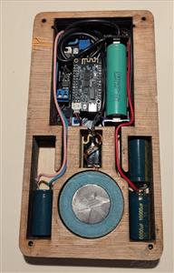
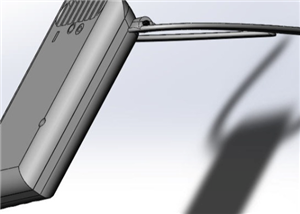
Here is how the box looks like when everything is in place:

Code has also been tested (without the electromagnet) and everything seems to work fine :
- enabling/disabling boost converter is tested
- ball detection is tested
- shoot triggering is tested (into a led)
Next step : triggering a real shot with the electromagnet...
Stay tuned : work in progress
"perpetual" motion ball
*PCBWay community is a sharing platform. We are not responsible for any design issues and parameter issues (board thickness, surface finish, etc.) you choose.


Raspberry Pi 5 7 Inch Touch Screen IPS 1024x600 HD LCD HDMI-compatible Display for RPI 4B 3B+ OPI 5 AIDA64 PC Secondary Screen(Without Speaker)
BUY NOW


- Comments(0)
- Likes(1)
More by Jean-Pierre Gleyzes
-
 RC radial engine spark plug heater
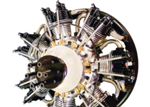
BackgroundMy friend bought this wonderful engine from UMS_technologiesIt's a 7 cylinders star engine...
RC radial engine spark plug heater
BackgroundMy friend bought this wonderful engine from UMS_technologiesIt's a 7 cylinders star engine...
-
 Convert a DC motor into a stepper one
This project is a way to convert a DC motor into a stepper motor.Of course "conversion" will not be ...
Convert a DC motor into a stepper one
This project is a way to convert a DC motor into a stepper motor.Of course "conversion" will not be ...
-
 OpenxSensor variometer and telemetry for RC planes
Ever wanted a very cheap variometer on your RC glider ?battery voltage monitoring ?extra RC channels...
OpenxSensor variometer and telemetry for RC planes
Ever wanted a very cheap variometer on your RC glider ?battery voltage monitoring ?extra RC channels...
-
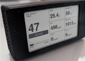 Air Quality station
OverviewThis DIY air quality monitoring system integrates precision sensors with a connected process...
Air Quality station
OverviewThis DIY air quality monitoring system integrates precision sensors with a connected process...
-
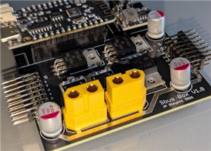 2S LiPo High-Current Power Box with two Sbus inputs
Project Overview: 2S LiPo High-Current Power Box with two Sbus inputsThis circuit is a high-performa...
2S LiPo High-Current Power Box with two Sbus inputs
Project Overview: 2S LiPo High-Current Power Box with two Sbus inputsThis circuit is a high-performa...
-
 Power box for big RC plane
Project Overview: 2S LiPo High-Current Power BoxThis circuit is a high-performance power distributio...
Power box for big RC plane
Project Overview: 2S LiPo High-Current Power BoxThis circuit is a high-performance power distributio...
-
 A bluetooth Joystick for TX16s radio (or others)
This project is kind of follow on of this one : Buddy Box for Radiomaster TX16sI decided to write an...
A bluetooth Joystick for TX16s radio (or others)
This project is kind of follow on of this one : Buddy Box for Radiomaster TX16sI decided to write an...
-
 Radiomaster TX16s buddy box (master/trainer and more)
I wanted a wireless buddy box for my Radiomaster TX16sThis buddy box would allow to wireless link tw...
Radiomaster TX16s buddy box (master/trainer and more)
I wanted a wireless buddy box for my Radiomaster TX16sThis buddy box would allow to wireless link tw...
-
 "perpetual" motion ball
Browsing internet and youtube, I found this mind blowing "perpetual motion" device designed by Willi...
"perpetual" motion ball
Browsing internet and youtube, I found this mind blowing "perpetual motion" device designed by Willi...
-
 Freon: Freeze On Neck - 3d printed box top
Freon project is fully describbed on this project page
Freon: Freeze On Neck - 3d printed box top
Freon project is fully describbed on this project page
-
 Freon: Freeze On Neck - 3d printed box bottom
Freon project is fully described on this project page
Freon: Freeze On Neck - 3d printed box bottom
Freon project is fully described on this project page
-
 Freon: Freeze On Neck personal cooler
DescriptionAre you tired of sweltering through hot days, feeling uncomfortable and unproductive?Imag...
Freon: Freeze On Neck personal cooler
DescriptionAre you tired of sweltering through hot days, feeling uncomfortable and unproductive?Imag...
-
 ESP32_StarMotor_glow plugs heater _ V2
BackgroundMy friend bought this wonderful engine from UMS_technologiesIt's a 7 cylinders star engine...
ESP32_StarMotor_glow plugs heater _ V2
BackgroundMy friend bought this wonderful engine from UMS_technologiesIt's a 7 cylinders star engine...
-
 RC plane CoG finder
IntroductionAs an intro here is a video of the system runningand another using the LCD displayA litt...
RC plane CoG finder
IntroductionAs an intro here is a video of the system runningand another using the LCD displayA litt...
-
 JP eCatFeeder
Overview In 2017 I published the first iteration of this project. And since then, the cat feeder had...
JP eCatFeeder
Overview In 2017 I published the first iteration of this project. And since then, the cat feeder had...
-
 ESP32_RC_Motor_tester_V2
FeaturesOn an RC plane, propeller performance depends on pitch, diameter, profile, and material.Test...
ESP32_RC_Motor_tester_V2
FeaturesOn an RC plane, propeller performance depends on pitch, diameter, profile, and material.Test...
-
 ESP32_RC_Motor_tester
FeaturesOn an RC plane, propeller performance depends on pitch, diameter, profile, and material.Test...
ESP32_RC_Motor_tester
FeaturesOn an RC plane, propeller performance depends on pitch, diameter, profile, and material.Test...
-
 FluidNC foam cutter controller
A few months ago I retrofited an old foam cutter based on a MM2001 hardware.This system works quite ...
FluidNC foam cutter controller
A few months ago I retrofited an old foam cutter based on a MM2001 hardware.This system works quite ...
-
Programmable Mist Maker - XIAO / QT PY Extension
222 0 0 -
RadioHAT - Raspberry Pi radio development platform
249 0 1 -
-
-
-
-
ARPS-2 – Arduino-Compatible Robot Project Shield for Arduino UNO
2801 0 5 -
A Compact Charging Breakout Board For Waveshare ESP32-C3
3304 3 8 -
AI-driven LoRa & LLM-enabled Kiosk & Food Delivery System
3585 2 2


