


RC plane CoG finder
Introduction
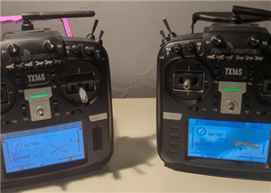
As an intro here is a video of the system running
and another using the LCD display
A little theory
To find the Center of Gravity of a plane (or anything else) you just need one scale and a ruler !
You will need to know the total weight of the plane and measure a moment from the leading edge of the wing:
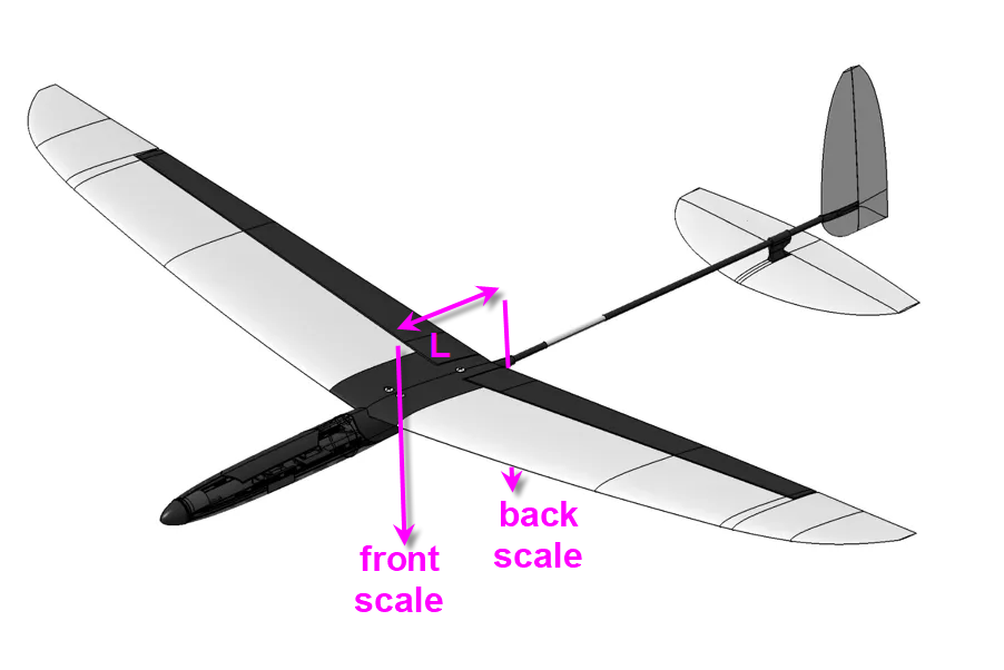
if W is the total Weight, Wb the weight read on the back scale and L the length of the lever between front and back pivots, then
CoG * W = L * Wb
or
CoG = L * Wb / W
This was the easiest solution when you have a single scale. Building such a device was extremely easy and is explained here : a "manual" CoG finder on thingiverse
The main "drawback" of this system is that it requires to weight the plane and then compute the formula anytime you change something into the mass of your model.
So I decided to add a second digital scale and a micro controller to have something more automatic !
When you have "front scale" and "back scale" weights (Wf and Wb) then the formula to find the CoG position relative to the leading edge of the wing is:
CoG = L * Wb/ (Wf + Wb)
That's frankly easy and the electronics to build such a system should be simple as well.
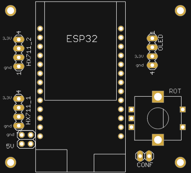
Electronics schematics
- the heart of the system is a Lolin32 lite ESP32 MCU.
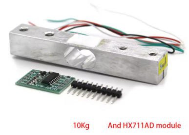
- and 2 load cells + HX711 amplifiers are needed as "digital scales"
- an Oled display is optionnaly added (if you don't have an Android phone !)
- a rotary encoder can help to tune values (if you don't have an Android phone)

And that's it... not complex at all !
Bill of Material can be found into the file sectin of this project
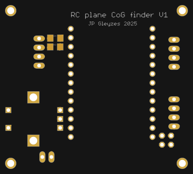
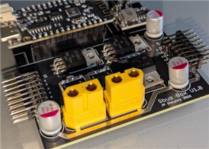
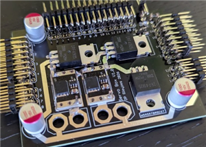
PCB
I have designed a nice and compact PCB allowing to fit the ESP32 and to connect all the sensors

The PCB was kindly sponsored by PCBWay and is as usual of excellent quality.

You can order it herediretly on this project page !
I must admit that this PCB is probably one of the simplest I have ever designed, but It's so cheap, delivered so fast and so professional looking that it worthed the time spent to design it !
And if you are new to PCBWay please use this affiliated link : https://pcbway.com/g/o35z4O
Power considerations
To power this board I will simply use an USB chord plugged into the ESP32 connector on one side and on any 5V power bank on the other one !
The lolin32 is equiped with a 3.3V linear regulator strong enough to deliver 1A current. Fairly enough for two loadcells and an 1" LCD !
LoadCells
I have choosen two 2kg loadcells. This is a good balance between sensitivity an max load. Most of my planes are gliders in the range 200g to 3kg. As the total weight of the plane is almost shared on the two scales, 3kg will put max 1.5kg on each scale... 2kg load cells add some safety margin !
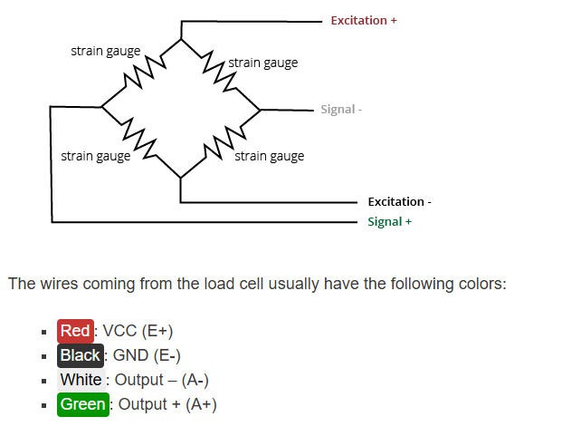
These devices need an amplifier HX711 to adapt their output.
Connection between load cell and amplifier follows this schematics:
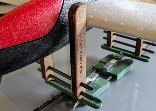
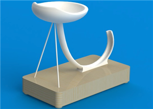
Plane stand and scales
The plane will be sitted on a stand, its wing leading edge touching the vertical side of the stand.
The stand itself will be put right above the two loadcells. Perpendicularity of feet must be insured so that the horizontal bars of the stand are trully horizontal. This is mandatory for accuracy of the "moment" computation
Both the stand and the scales must be adjustable in width and lenght to accomodate most of the RC planes.
building the stand

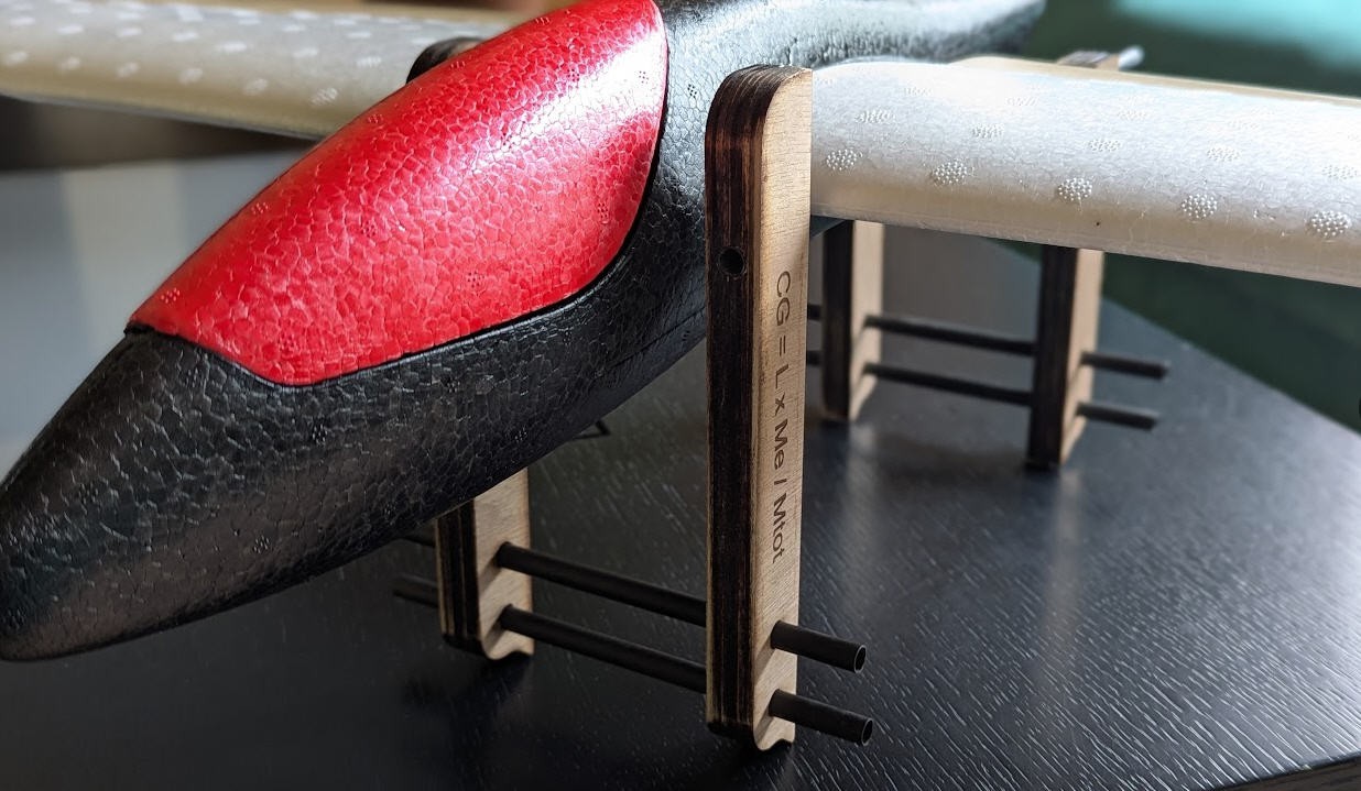
As you can see the length "L" is measured between the two vertical sides of the stand.
Here is the stand with a small foamy flying wing:
The stand can be 3d printed or laser cut. Both options are available.
If you choose the laser cut option (what I did) then cut the “CoGfinder_flat.dxf” file into 5mm plywood. Then glue each foot with 3 parts (the slot one in the middle). Let the glue dry and drill the square slot at 7mm (start at 5 then 6 then 7)… Adjust the hole so that your carbon arrow slides with a some friction into the holes.
If you choose the 3d printed option, then it's even easier : print “front_3d.stl” and “back_3d.stl” files twice, and adjust the holes!
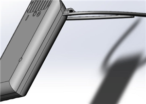
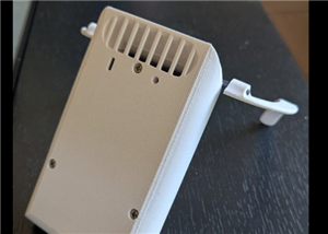
building the scales
The scales are 3d printed.
The loadcells can be screwed on the scales with 5mm screws. While the top of the loadcell has 4mm holes… (don't ask me why) so that the “ruler” will be screwed with 4mm screws.
You will have to insert the HX711 amplifiers into the slot and solder the wires, then glue the cover.
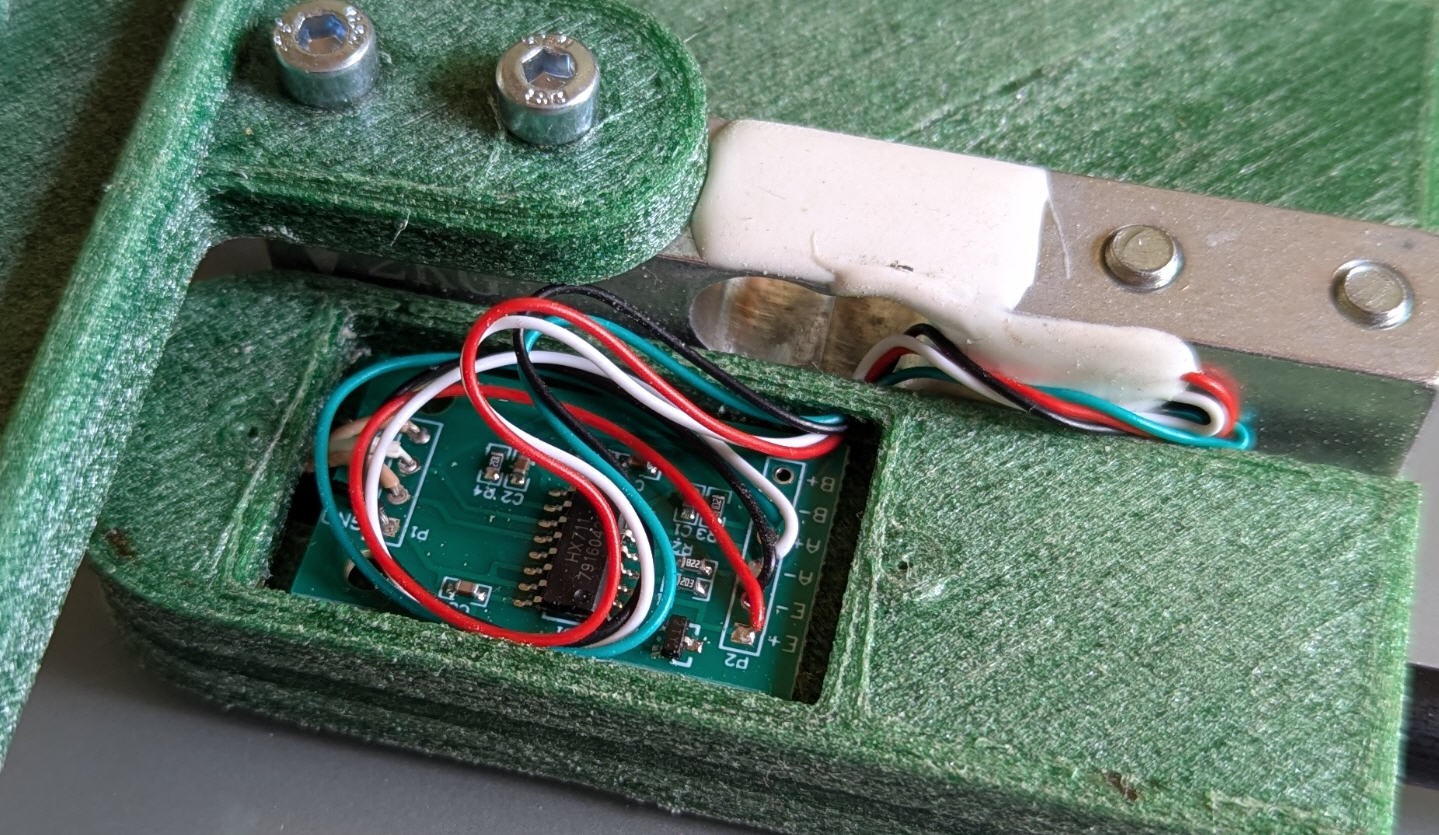
The 2 scales are strictly identical and can slide one into the other with the help of carbon arrow pipes inserted into the holes. One side is fixed, while the other (through hole) must slide around the arrow. Adjust the holes to get this behavior.
While finished the scales should look like this !
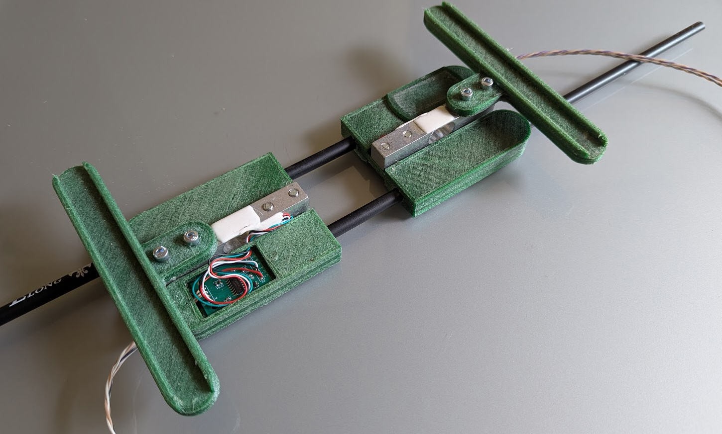
Once the stand and the scales are finished, you can put one above the oher and use your CoG finder device !

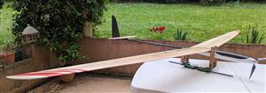
This was with a very small plane... But will it work with bigger ones ?

Tune width anf length of the CoGfinder and... The answer is yes ! It was easier to install the plane rather than shooting a picture with these 2.7m long wings !
Software
Software will be composed of
- firmware embeded into the ESP32
- Android Application (optionnal) communicating with the ESP32 via UDP over Wifi (either in "station mode" or in"Access Point" mode)
If you don't have an Android phone, you will need to use the "standalone" option where all the settings and displays will be done with a rotary encoder and a small 1" Oled display.
Currently these options are not yet developped (stay tuned !)
If you have an Android phone then you are lucky as you will get much more user fiendly interface !
Android App
This app will offer two modes of operation:
- CoG finder
- CoG finder + "lead" helper
CoG mode
here is the screen when selecting "CoG" mode of operation

You'll just have to enter the L value, it will be sent to the ESP32 board, then scales will output the "front scale" and "back scale" weights and the CoG position will be computed !
Move your battery into the plane and the CoG will move in real time !
Now if you can't get the right CoG position then you will have to add lead either to the nose or to the tail of your plane. But how much ? This will be easier when using the "CoG-lead" mode of operation
CoG-lead mode
Here is the screen of this mode
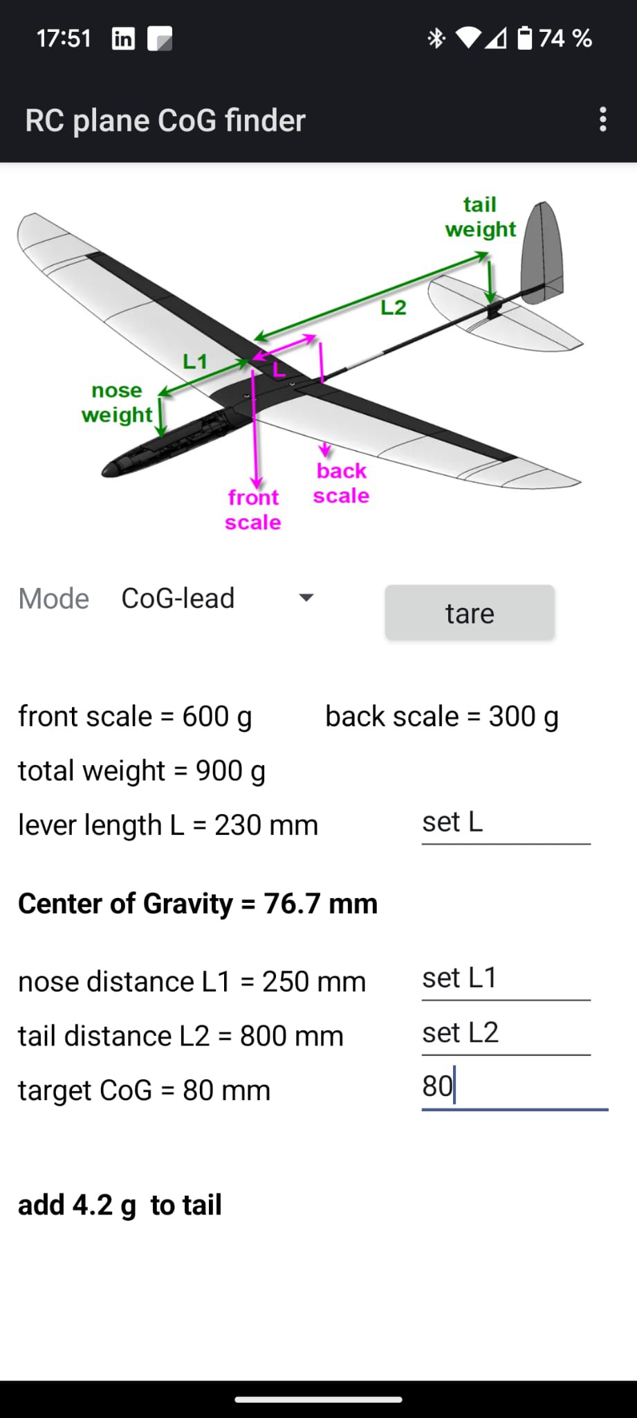
Centering the plane could be done either with lead into the nose at L1 distance from the leading edge of the wing or with lead into the tail at L2 distance from the leading edge.
After entering the target CoG position, L1 and L2 values, the app will automatically tell you where to add lead and compute the mass to be added.
(in the above example, CoG is at 76.7mm and should be at 80mm, the plane is "nose heavy" you have to add 4.2g of lead into the tail at 800mm from the leading edge.)
Note that target CoG, L, L1 and L2 will be sent to the ESP32 board and permanently stored into its flash. So you can center your plane during several days without loosing your settings !
Your plane database
The android App allows now to keep track of all planes into ta database.
The data base is accessible here on top of the screen
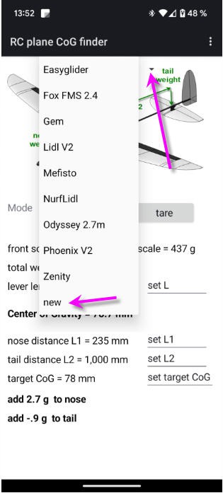
to add a new plane click on the "new" item
You can modify the values and when ready save again the plane with the menu

Similarly you can delete the current plane.
There is also an option to export the whole database into a .csv file that you can open with any spreadsheet viewer

Using Bluetooth Low Energy
If your Android phone is modern enough (BLE appeared in 2010) then you are lucky as you can use the Android App and the CoGfinder almost "magically"
- turn on Bluetooth on your phone
- launch the App
- power the ESP32
and that's it, no password, no pairing... It just works !
configuring the wifi
If you have an old phone, you can still use Wifi.
First uncomment the line "HAS_WIFI" to allow this option
//#define HAS_WIFI //leave this line commented if you only want Bluetooth Low Energy ; uncomment for both Wifi and BLE
Then compile the firmware and follow this procedure .
There are two ways to configure the wifi:
- The ESP32 connects to your router (Station mode)
- The ESP32 acts as an Access Point (Access Point mode)
Station mode
To configure the wifi simply follow this procedure:
I have used the ESP32 WifiManager library capabilities to enter wifi credentials on the ESP32 board.
So if you boot the board (or reset it with the reset button) while shorting the "CONF" pin header on the lower right corner of the board, then the ESP32 exposes a Wifi hotspot (named "JP RC_CoG_finder" on which you can connect any smartphone (or PC)
Connecting to it will automatically open a configuration window

You then have to choose an exisitng wifi network for which you have the credentials, and enter them into the form.
Your ESP32 board is now configured to run with wifi and you would be able to monitor your scales with the android App. (don't forget toremove the shortonthe CONF pin header !).
Your phone will still be connected to internet. So this is the best solution to use if you have wifi close to your current position !
Access Point mode
If you are away from wifi then you can still use your phone but with the following limitations:
- your phone must be disconnected from internet (5G and wifi)
- your phone can connect to the Access Point that will exppose the ESP32
To activate this mode you will have to reset the ESP32 while pressing the rotary encoder button
Then the access point (named "JP RC_CoG_finder") will be into the list of Wifi routers in your phone. Connect to it and launch the App !
loadcells calibration
As any digital scales yours need to be calibrated.
tare
The first (obvious) calibration is the "tare". Tare button (or menu) will give you 0 g on both scales. Tare is automatically done during boot but must manually be done when you place the plane stand on the scales.
scales sensitivity calibration
This calibration should be done only once (with new cells) or when you detect a drift in the measured weights.
- remove the plane stand
- push the tare button
- place 500g of calibrated weight on the front scale

- click on the three dots menu (top right corner) and select "calib front scale" menu
- do the same for the back scale
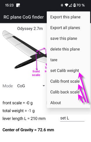
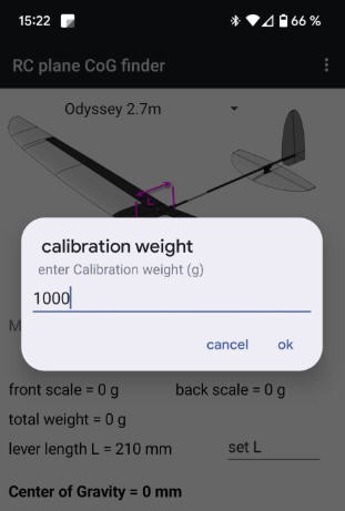
If you want to calibrate for another weight then you'll have to enter this weight with the "set Calib weight" menu
Oled display and menus
if you don't have an android phone you can still use the device in stand alone mode.
The rotary encoder and the Oled display can be used to control the CoGfinder.
Any modification you do into the parameters will be synchronized between android App and ESP32 board. Easy !
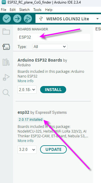
Firmware compilation
Some of the libraries require quite old configuration for the Espressif board manager.
So select "board manager", type "ESP32" into the search box, then select version 2.0.17 and install
RC plane CoG finder
*PCBWay community is a sharing platform. We are not responsible for any design issues and parameter issues (board thickness, surface finish, etc.) you choose.


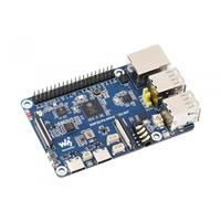


Raspberry Pi 5 7 Inch Touch Screen IPS 1024x600 HD LCD HDMI-compatible Display for RPI 4B 3B+ OPI 5 AIDA64 PC Secondary Screen(Without Speaker)
BUY NOW


- Comments(3)
- Likes(0)
More by Jean-Pierre Gleyzes
-
 RC radial engine spark plug heater
BackgroundMy friend bought this wonderful engine from UMS_technologiesIt's a 7 cylinders star engine...
RC radial engine spark plug heater
BackgroundMy friend bought this wonderful engine from UMS_technologiesIt's a 7 cylinders star engine...
-
 Convert a DC motor into a stepper one
This project is a way to convert a DC motor into a stepper motor.Of course "conversion" will not be ...
Convert a DC motor into a stepper one
This project is a way to convert a DC motor into a stepper motor.Of course "conversion" will not be ...
-
 OpenxSensor variometer and telemetry for RC planes
Ever wanted a very cheap variometer on your RC glider ?battery voltage monitoring ?extra RC channels...
OpenxSensor variometer and telemetry for RC planes
Ever wanted a very cheap variometer on your RC glider ?battery voltage monitoring ?extra RC channels...
-
 Air Quality station (e-paper and Home Assistant)
OverviewThis DIY air quality monitoring system integrates precision sensors with a connected process...
Air Quality station (e-paper and Home Assistant)
OverviewThis DIY air quality monitoring system integrates precision sensors with a connected process...
-
 2S LiPo High-Current Power Box with two Sbus inputs
Project Overview: 2S LiPo High-Current Power Box with two Sbus inputsThis circuit is a high-performa...
2S LiPo High-Current Power Box with two Sbus inputs
Project Overview: 2S LiPo High-Current Power Box with two Sbus inputsThis circuit is a high-performa...
-
 Power box for big RC plane
Project Overview: 2S LiPo High-Current Power BoxThis circuit is a high-performance power distributio...
Power box for big RC plane
Project Overview: 2S LiPo High-Current Power BoxThis circuit is a high-performance power distributio...
-
 A bluetooth Joystick for TX16s radio (or others)
This project is kind of follow on of this one : Buddy Box for Radiomaster TX16sI decided to write an...
A bluetooth Joystick for TX16s radio (or others)
This project is kind of follow on of this one : Buddy Box for Radiomaster TX16sI decided to write an...
-
 Radiomaster TX16s buddy box (master/trainer and more)
I wanted a wireless buddy box for my Radiomaster TX16sThis buddy box would allow to wireless link tw...
Radiomaster TX16s buddy box (master/trainer and more)
I wanted a wireless buddy box for my Radiomaster TX16sThis buddy box would allow to wireless link tw...
-
 "perpetual" motion ball
Browsing internet and youtube, I found this mind blowing "perpetual motion" device designed by Willi...
"perpetual" motion ball
Browsing internet and youtube, I found this mind blowing "perpetual motion" device designed by Willi...
-
 Freon: Freeze On Neck - 3d printed box top
Freon project is fully describbed on this project page
Freon: Freeze On Neck - 3d printed box top
Freon project is fully describbed on this project page
-
 Freon: Freeze On Neck - 3d printed box bottom
Freon project is fully described on this project page
Freon: Freeze On Neck - 3d printed box bottom
Freon project is fully described on this project page
-
 Freon: Freeze On Neck personal cooler
DescriptionAre you tired of sweltering through hot days, feeling uncomfortable and unproductive?Imag...
Freon: Freeze On Neck personal cooler
DescriptionAre you tired of sweltering through hot days, feeling uncomfortable and unproductive?Imag...
-
 ESP32_StarMotor_glow plugs heater _ V2
BackgroundMy friend bought this wonderful engine from UMS_technologiesIt's a 7 cylinders star engine...
ESP32_StarMotor_glow plugs heater _ V2
BackgroundMy friend bought this wonderful engine from UMS_technologiesIt's a 7 cylinders star engine...
-
 RC plane CoG finder
IntroductionAs an intro here is a video of the system runningand another using the LCD displayA litt...
RC plane CoG finder
IntroductionAs an intro here is a video of the system runningand another using the LCD displayA litt...
-
 JP eCatFeeder
Overview In 2017 I published the first iteration of this project. And since then, the cat feeder had...
JP eCatFeeder
Overview In 2017 I published the first iteration of this project. And since then, the cat feeder had...
-
 ESP32_RC_Motor_tester_V2
FeaturesOn an RC plane, propeller performance depends on pitch, diameter, profile, and material.Test...
ESP32_RC_Motor_tester_V2
FeaturesOn an RC plane, propeller performance depends on pitch, diameter, profile, and material.Test...
-
 ESP32_RC_Motor_tester
FeaturesOn an RC plane, propeller performance depends on pitch, diameter, profile, and material.Test...
ESP32_RC_Motor_tester
FeaturesOn an RC plane, propeller performance depends on pitch, diameter, profile, and material.Test...
-
 FluidNC foam cutter controller
A few months ago I retrofited an old foam cutter based on a MM2001 hardware.This system works quite ...
FluidNC foam cutter controller
A few months ago I retrofited an old foam cutter based on a MM2001 hardware.This system works quite ...
-
Programmable Mist Maker - XIAO / QT PY Extension
553 1 0 -
RadioHAT - Raspberry Pi radio development platform
438 0 1 -
-
-
-
-
ARPS-2 – Arduino-Compatible Robot Project Shield for Arduino UNO
2950 0 6 -
A Compact Charging Breakout Board For Waveshare ESP32-C3
3463 3 8 -
AI-driven LoRa & LLM-enabled Kiosk & Food Delivery System
3806 2 2


